CHAPTER 5 ROCK MASS STRENGTH 5 1 INTACT

")
 • Intact rock, which refers to the unfractured blocks")


 • In 1964 D. U. Deere introduced an index to")


")


 as a measure for the number")


")
")

 Lengths of rock pieces in a 60 cm")
 Calculate RQI, Q based on the following information Data Value")

 x (Jr/Ja) x (Jw/SRF) The known values are as")
 RMR • The Rock Mass Rating (RMR) System is a geomechanical")


")


- Slides: 36
CHAPTER 5 ROCK MASS STRENGTH
5. 1 INTACT ROCK • Two main mechanical components of a rock mass: a) the intact rock material b) the fractures (e. g: faults, joints and bedding planes)
5. 1 INTACT ROCK (CONT) • Intact rock, which refers to the unfractured blocks that exist between structural discontinuities
• In engineering, the rock type is classified according to its potential mechanical performance and a rock quality is determined. • So, the rock is described by its strength, stiffness, anisotropy, porosity, grain size and shape etc.
DID YOU KNOW? Stonehenge is one of the examples of sandstone with a siliceous matrix that able to resist 5000 years of British weather. Factors how the rock can be degraded with time include: • Exposure to water • Freeze-thaw cycles • Chemical effects
5. 2 ROCK MASS • Rock mass" is defined as the rock material together with the three dimensional structure of discontinuities
5. 2 ROCK MASS • Failure of a rock mass occurs when a combination of stress, strain, temperature and time exceeds a certain critical limit. There are three different primary rock failure mechanisms that can be observed in hard rock • - tensile failure, • - spalling (extensional failure), and • - shear failure.
5. 2 ROCK MASS • Instability of rock masses is often characterized by: • – Block failure – structurally controlled failures (loosening, block fall). • – Failures induced from overstressing -overstressing of massive rock (spalling, popping, strain burst) -overstressing of jointed rock (shear failure, buckling) - overstressing of granular materials (soils, heavily jointed rocks • Instability in faults and weakness zones. For large scales, a fault or weakness zone can be treated as a joint.
ROCK QUALITY DESIGNATION (RQD) • In 1964 D. U. Deere introduced an index to assess rock quality quantitatively, called rock quality designation (RQD) The RQD is a core recovery percentage that is indirectly based on the number of fractures in the rock mass that is observed from the drill cores.
DID YOU KNOW? • The RQD is defined as the percent ratio of the sum of core pieces with higher than 10 cm (4 in) length to the total drill run. • Based on the percent or RQD from 0 -100% the rock mass quality can be assessed. • For example based on the proposal by Deere, rock mass with RQD<25% is characterized as “very poor”. If RQD is higher than 75% it is classified as “Good”.
HOW TO OBTAIN SAMPLES OF INTACT ROCK? Samples of the intact rock can be obtained from surface outcrops or from borehole cores obtained during a site investigation. Using a coring drill bit, a cylindrical sample of the intact rock can be obtained from boreholes as shown in Figure
RQD EXAMPLE 1
RQD EXAMPLE 1 (cont)
RQD • The advantages of RQD are its • simplicity, • quick determination, and • inexpensive
RQD
RQD
RQD CONT… A simple relationship which may used to convert Jv into RQD for clay-free rock masses is: RQD = 115 − 3. 3 Jv Where Jv is represents the total number of joints per cubic meter or the volumetric joint count.
RQD CONT… Jv has been described by Palmstrom(1986) as a measure for the number of joints within a unit volume of rock mass defined by: Where Si is the average joint spacing in metres for the joint set and J is total number of joint sets except the random joint set.
RQD example 2
RQD CONT…
RQD example 3
CONT…(example 3)
RQD CONT…(example 3)
RQD CONT…
CRP EXAMPLE The core recovery percentage(%) Lengths of rock pieces in a 60 cm rock core are measured to be 2, 3, 1, 4. 5, 5. 5, 2, 6, 8, 3, 2, 15 cm. Solution STEP 1: Find the recovery percentage. The total length of all the pieces is added to be 52 cm
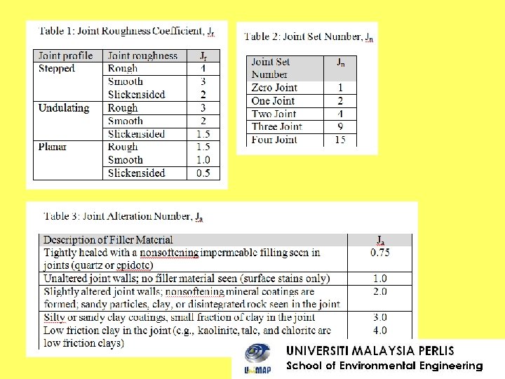
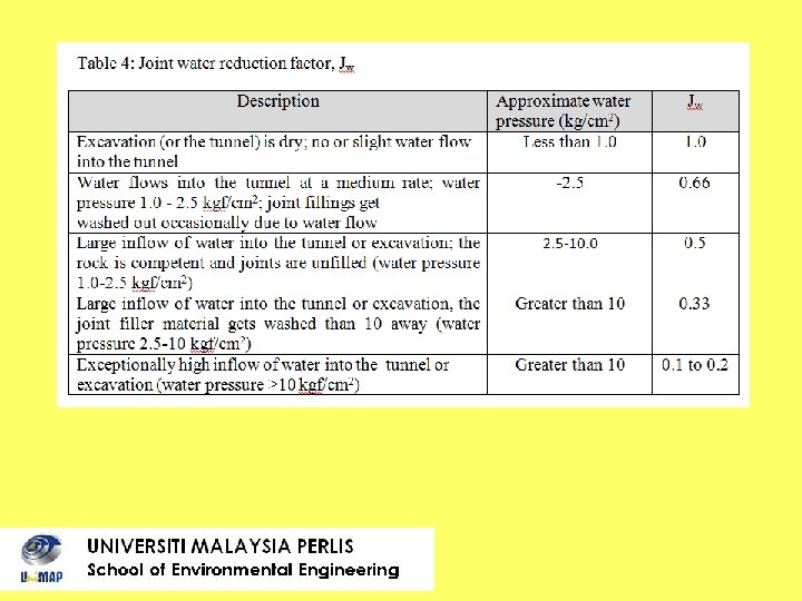
ROCK QUALITY INDEX (RQI) Calculate RQI, Q based on the following information Data Value Rock Quality Design, RQD 60% Undulating rough joint Joint Set Number 2 Small fraction of clay in the joint Stress Reduction Factor, SRF 5 Water flows into the tunnel at a medium rate
Data Value Rock Quality Design, RQD 60% Undulating rough joint Joint Set Number 2 RQD = 60 Jr = 3 (Table 1) Jn = 4 (Table 2) Small fraction of clay in the joint Ja = 3 (Table 3) Stress Reduction Factor, SRF = 5 5 Water flows into the tunnel at a medium rate Jw = 0. 66 (Table 4)
SOLUTION, Q Q = (RQD/Jn) x (Jr/Ja) x (Jw/SRF) The known values are as follows. RQD = 60%. Since there are two sets of joints, Jn = 4 (Table 2). From Table 1, for undulating, rough joints, Jr = 3. From Table 3, since most joints are filled with silts and sands, Ja = 2. From Table 4, Jw = 0. 66. From the text above, SRF = 5. Hence Q = (60/4) x (3/3) x (0. 66/5) = 1. 98
(ROCK MASS RATING) RMR • The Rock Mass Rating (RMR) System is a geomechanical classification system for rocks, developed by Z. T. Bieniawski between 1972 and 1973. • It combines the most significant geologic parameters of influence and represents them with one overall comprehensive index of rock mass quality, which is used for the design and construction of excavations in rock, such as tunnels, mines, slopes and foundations.
The following six parameters are used to classify a rock mass using the RMR system • • • Uniaxial compressive strength of rock material Rock quality designation (RQD) Spacing of discontinuities Condition of discontinuities Groundwater conditions Orientation of discontinuities Each of the six parameters is assigned a value corresponding to the characteristics of the rock. These values are derived from field surveys and laboratory tests. The sum of the six parameters is the "RMR value", which lies between 0 and 100.
RMR CONT. • These parameters are evaluated in the field & given the respective point scoring. • Numerical rating on the 6 parameters (according to observation) gives RMR value 0 – 100 & this range of values classifies rock mass into 5 main groups:
RMR CONT. • • • Group I: RMR = 80 – 100 (RMR rating) Group II: RMR = 60 - 80 Group III: RMR = 40 - 60 Group IV: RMR = 20 - 40 Group V: RMR = < 20
RMR CONT. • Higher rock mass rating indicates better rock mass condition/quality. • In terms of quality & strength rock mass, Group I is more suitable for excavation of tunnel or slope relative to group II or III.
RMR APPLICATIONS • Most of the applications of RMR have been in the field of tunnelling but also in various types of slopes for slope stability analysis, foundation stability, caverns and different mining applications.