Chapter 44 Commercial Construction Projects Introduction Major differences


 • Prime differences between commercial and residential drafting – Working")


 • Floor plans – Shows location of materials • Floor")
 • Schedules – Door schedules and symbols – Window schedules")
 • Roof plans – Show shape, roofing materials, direction of")
 • Roof plans (cont’d. ) – Common components • •")
 • Exterior elevations – Show structure exterior as projected from")
 • Sections show: – Vertical relationships of materials represented on")
 • Types of sections – Full sections • Longitudinal or")
 • Enlarged floor plans – Used for components that must")
 • Vertical circulation drawings – Ramps – Stairs • Material")
 • Exterior details – Details may related to any architectural")

 • Construct skeleton of the structure (cont’d. ) – Structural")


- Slides: 25
Chapter 44 Commercial Construction Projects
Introduction • Major differences regarding commercial drafting – Team effort • Within the office • Consulting firms (designer and drafters) – Wider variety of materials • Emphasis on environmentally friendly materials
Office Practice • As ability and quality improves, so will the variety of projects – Tools include: • Sweet Network • Master. Format • Simpson Strong-Tie catalog
Office Practice (cont’d. ) • Prime differences between commercial and residential drafting – Working with engineer’s calculations • • Provided for entire structure Details everything Specific area and stress Most start at highest level and work down
Drawing Organization • Drawing origination – Usually starts with residential drawings • Commercial projects are arranged in seven groups • Drawing set page designators – Drawings can be numbered in successive order using a designator • Drawing placement – Details are planned prior to drawings
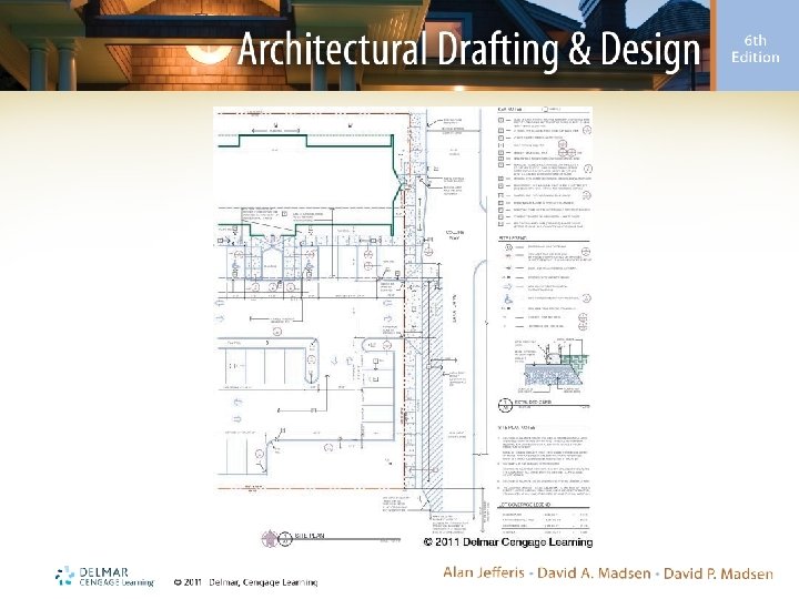
Site Drawings • Basis for all other site-related drawings – Property layout and size – Outline of the structure – North arrow – Ground and finish floor elevations – Setbacks – Parking and access information – Information about utilities
Architectural Drawings • Describe size and shape of a structure – Floor plans and enlarged floor plan – Elevations – Wall sections – Roof plan – Reflected ceiling plan – Interior elevations and details – Finish schedules
Architectural Drawings (cont’d. ) • Floor plans – Shows location of materials • Floor plan symbols – North arrow – Grid markers – Section markers – Detail markers – Elevation symbols
Architectural Drawings (cont’d. ) • Schedules – Door schedules and symbols – Window schedules and symbols – Interior finish symbols – Finish symbols and schedules – Symbols to clarify materials – Wall construction symbols
Architectural Drawings (cont’d. ) • Roof plans – Show shape, roofing materials, direction of slope, and drainage method of each surface • Low-sloped roofs • High-sloped roofs • Roof materials (e. g. , single-ply, built-up, seamed metal, and corrugated metal)
Architectural Drawings (cont’d. ) • Roof plans (cont’d. ) – Common components • • • Changes in roof shape Roof openings Roof drainage Gutters Drains, overflow drains, and scuppers
Architectural Drawings (cont’d. ) • Exterior elevations – Show structure exterior as projected from floor plan • • • Heights from floor to ceiling and floor to wall Floor to ceiling for multilevel structures Floor to rails at balconies or above-ground decks Window height and size Height and width of exterior finishes Roof pitches
Architectural Drawings (cont’d. ) • Sections show: – Vertical relationships of materials represented on each plan view and exterior elevations – Materials used to construct walls, floors, ceilings, and roof components and vertical relationships
Architectural Drawings (cont’d. ) • Types of sections – Full sections • Longitudinal or transverse – Wall sections • Other considerations – Material representation – Dimensions – Drawing symbols and notations
Architectural Drawings (cont’d. ) • Enlarged floor plans – Used for components that must be displayed at a larger scale to provide detailed information • Interior elevations – Show shape and finishes of features built into a wall • Reflected ceiling plans – Shows ceiling of a specific level of a structure
Architectural Drawings (cont’d. ) • Vertical circulation drawings – Ramps – Stairs • Material • Sections – Elevator drawings – Escalator drawings
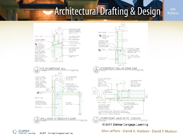
Architectural Drawings (cont’d. ) • Exterior details – Details may related to any architectural sheet • Exterior joints and intersections of various materials • Interior details – Details may related to any architectural sheet • Door and finish details
Structural Drawings • Construct skeleton of the structure – Framing plans • Wood and timber • Structural steel • Precast concrete – Structural elevations • Structural steel • Poured concrete • Tilt-up concrete
Structural Drawings (cont’d. ) • Construct skeleton of the structure (cont’d. ) – Structural sections • Show material intersections – Structural details • Provide information to make required connections – Foundation plans • Plan view floor system construction • Specifies size and location of concrete pours
Electrical Drawings • Provide information about: – Locations of: • Outlets • Switches • Light fixtures – Other related information
Fixture Drawings • Used for structures containing a large number of specialty cabinet or trim drawings – Fixture drawings will be in their own section • Will be in successive order (starting with F-1) – Include details covering interior trim and specialized equipment, as well as cabinets
Mechanical Drawings • Show movement of air throughout the structure – Location of heating and cooling equipment – Duct runs
Plumbing Drawings • Show fresh water and wastewater will be routed throughout the structure – Plumbing drawings, schedules, and details are successively arranged (starting with page P-1)