Chapter 40 Automatic Transmissions and Transaxles Automatic Transmissions


- Slides: 45
Chapter 40 Automatic Transmissions and Transaxles
Automatic Transmissions and Transaxles • Selects gear ratios according to engine speed, power train load, vehicle speed, and other operating factors. • Most have four speeds with an overdrive fourth gear. • Many have five, six, and up to eight speeds.
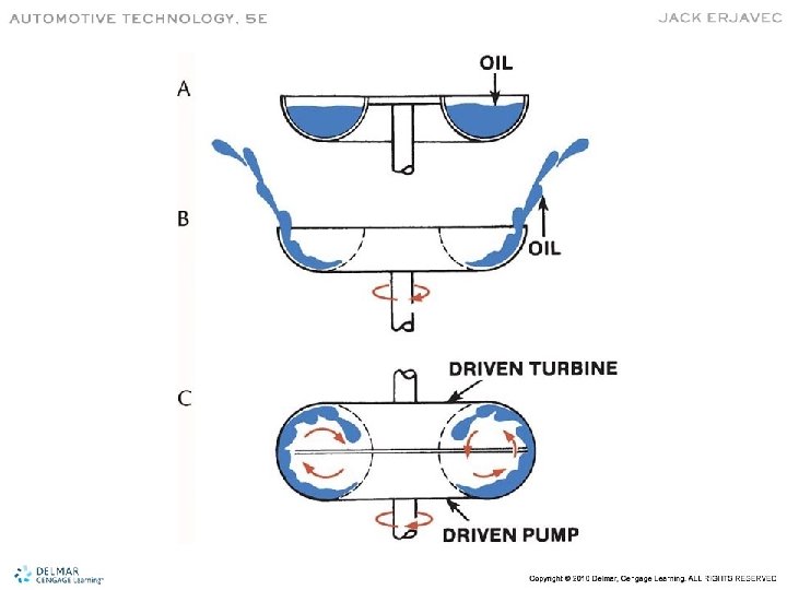
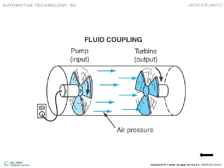
Torque Converter • A fluid clutch or coupling that transfers torque from the engine to the transmission. • Automatically engages and disengages power from the engine in relation to RPM. • At idle, there is not enough fluid flow for power transfer. • As RPM increases, fluid flow is sufficient to transmit engine power.
Torque Converter Internal Parts
Torque Converter Components • Impeller or Pump Assembly – Receives power from the engine. • Turbine – Transfers power to the transmission main shaft. • Stator – Is the torque multiplier. • Overrunning clutch – Allows the stator to turn in only one direction.
Basic Operation • Transmission fluid is the medium to transfer energy. • The faster the impeller rotates, the greater energy the fluid has to transfer. • The fluid leaving the impeller acts on the turbine. • The turbine drives the transmission input shaft.
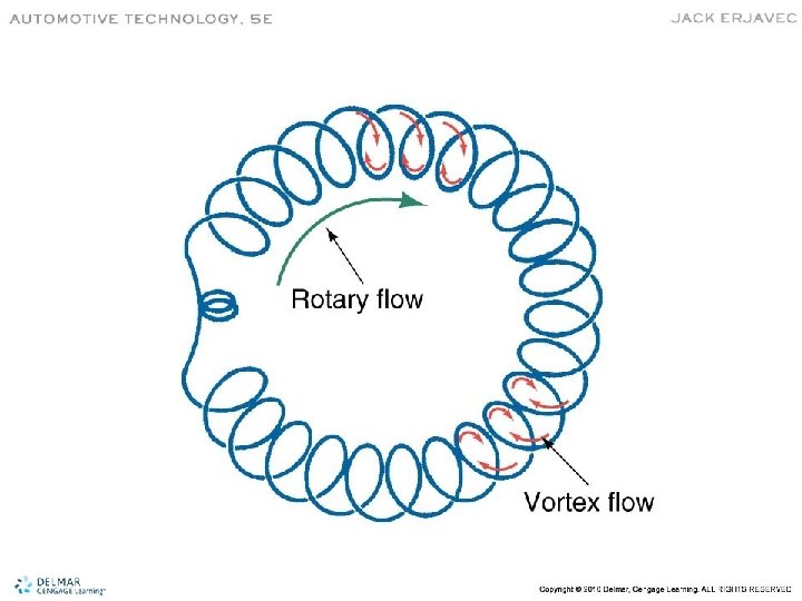
Types of Oil Flow • Rotary Flow – Oil flow around the circumference caused by rotation of the torque converter on its axis • Vortex Flow – Oil flow from the impeller to the turbine and back to the impeller • Coupling point is when turbine speed approaches impeller speed
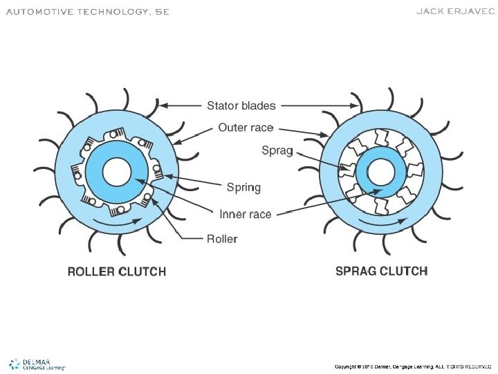
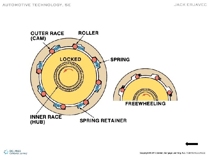
Overrunning Clutch • Keeps the stator from rotating when driven in one direction. • The stator is locked when there is a difference between the turbine and impeller speeds.
Lockup Torque Converter • Eliminates the 10% slip between the impeller and turbine. • Improves fuel economy. • Reduces operational temperature. • Most torque converter clutches (TCC) use electronically controlled hydrualic pistons.
Planetary Gearset
Planetary Gear Operation • When the planetary carrier is the input, an overdrive condition is produced. • When the planetary carrier is the output, an underdrive condition is produced. • When the planet carrier is held, reverse gear is produced.
Types of Compound Gearsets • Simpson – Has two separate planetary gearsets with a common sun gear. • Ravigneaux – Has two separate sun gears, two separate planetary gears, and a common ring gear.
Simpson Gearset
Ravigneaux Gearset
Other Transmission Designs • Nonplanetary Gearset Type – Uses constant mesh gears similar to a manual transmission. • Continuously Variable Type (CVT) – Has no fixed forward speeds. – Uses belts and pulleys to provide variable ratios.
CVT Transmission
Lepelletier System • Used in late model 6 -, 7 -, and 8 -speed transmissions. • Combines a simple gear set with a Ravigneaux gear set. • Many are more compact than most four- and five-speed automatics.
Apply Devices • Bands – Are typically used as a holding device. • Servos – Are used to apply the band. • Multiple Friction Disc Assemblies – Are used to hold or apply.
Transmission Bands • A braking assembly positioned around a stationary or rotating drum or carrier.
Typical Simple Servo
Transmission Clutches • Able to hold and drive planetary gear members. • Overrunning clutches are used to hold or drive members of the gearset. • Both sprag and roller overrunning clutches are used.
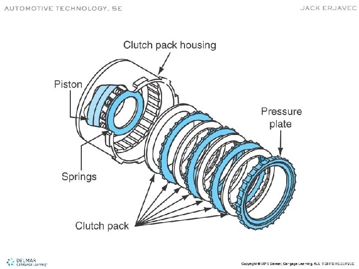
Multiple-Disc Clutches • A series of friction discs and steel plates used to transmit torque or apply braking force. • Internal teeth mesh with clutch hub. • External teeth mesh with internal splines in transmission housing or clutch drum.
Bearings, Bushings, and Thrust Washers • Bearings are used to reduce wear and friction: – Most either slide or roll against the surface • Bushings are pressed into place: – Support rotating parts, guide parts, and control fluid flow • Thrust washers may act as a bearing and a spacer to control endplay.
Typical Bearing Locations
Bushing Locations
Snap Rings • Both internal and external types are used. • Internal snap rings hold servo and clutch assemblies together. • May also be used to adjust clearances.
Gaskets and Seals • Gaskets – Seal two parts together or prevent fluid flow – Classified as either hard or soft gaskets • Seals – Used to seal fluid around valves, shafts, and other moving parts
Seal Classifications • Static – Is used between two parts that do not move. • Dynamic – Is used between two parts that move with either rotating or reciprocating motion. • Positive – Prevents all fluid leakage. • Non-positive – Allows a controlled amount of leakage. – Is used to lubricate a moving part.
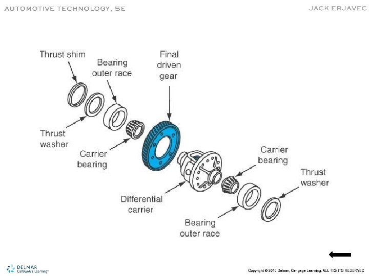
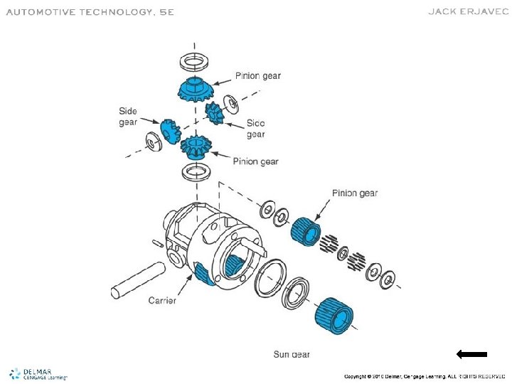
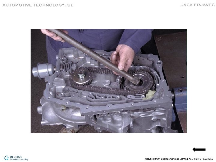
Final Drive Assemblies • Transmit transaxle output to the differential section. • Four common configurations: – Helical gear – Planetary gear – Hypoid gear – Chain drive
Hydraulic System • The fluid operates, lubricates, and cools the transmission. • The pump is the source of all fluid flow: – Pressure-regulating valves change fluid pressure to control shift quality and shift points – Flow-directing valves send to fluid to the correct apply device for gear changes
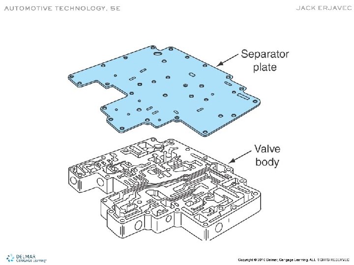
Valve Body • Distributes and controls pressurized fluid throughout the transmission. • Made of two or three main components: – Valve body – Separator plate – Transfer plate
• Check ball valves • Poppet valves • Spool valves
Shift Quality • Shift feel is controlled by the pressure at which each hydraulic member is applied or released. • Timing between band clutch application to prevent engine flare-up or clutch and band slippage.
Shift Timing • Determined by throttle pressure and governor pressure acting on opposite sides of the shift valve.
Hydraulic Circuits • The hydraulic circuit for each gear selector position is explained in the flow charts. • While examining flow charts, note gear range, torque converter mode, engaged planetary controls, approximate vehicle speed, and throttle position.