Chapter 4 Techniques of Circuit Analysis So far


 All nodes ? The nodes are a, b, c, d, e, f and")
 The essential nodes ? A node where three or more circuit elements join")
 All branches ? A path that connects two nodes The branches are")
 All essential branches ? A path that connects two essential nodes without passing")
 All meshes ? The meshes are")
 Two paths that are not loops or essential branches ? is a paths")
 Two loops that are not meshes ? is a loop , but it")


 like a ,")


 Applying KVL")


 find the power associated with the 6 V source (b)")

 use source transformations to find the voltage vo ? Since")


- Slides: 103
Chapter 4 Techniques of Circuit Analysis So far we have analyzed relatively simple resistive circuits by applying KVL and KCL in combination with Ohm’s law. Applying KVL and Ohm’s law, we have, Solving for i , we have, However as circuit become more complicated and involve more elements, this direct method become cumbersome ( ﻣﺮﻫﻘﺔ , )ﻏﻴﺮ ﺳﻬﻞ
However as circuit become more complicated and involve more elements, this direct method become cumbersome ( ﻣﺮﻫﻘﺔ , )ﻏﻴﺮ ﺳﻬﻞ In this chapter we introduce two powerful techniques of circuit analysis that aid in the analysis of complex circuit which they are known as Node-Voltage Method or Nodal Analysis Mesh-Current Method or Mesh Analysis In addition to these method we will develop other method such as source transformations, Thevenin and Norton equivalent circuit.
4. 1 Terminology Planar Circuit : a circuit that can be drawn on a plane with no crossing branches as shown The circuit shown can be redrawn which is equivalent to the above circuit Planar Circuit
The circuit shown is non planar circuit because it can not be redrawn to make it planar the circuit
Describing a Circuit – The vocabulary Consider the following circuit Node Essential node path A point where two or more circuit elements join a A node where three or more circuit elements join b A trace of adjoining basic elements with no elements included branch A path that connects two nodes Essential branch A path that connects two essential nodes without passing through an essential node loop mesh Planar Circuit A path whose last node is the same as the starting node A loop that does not enclose any other loops A circuit that can be drawn on a plane with no crossing branches
Example 4. 1 For the circuit identify the following
(a) All nodes ? The nodes are a, b, c, d, e, f and g
(b) The essential nodes ? A node where three or more circuit elements join The essential nodes are b, c, e and g
(c) All branches ? A path that connects two nodes The branches are
(d) All essential branches ? A path that connects two essential nodes without passing through an essential node The essential branches are
(e) All meshes ? The meshes are
(f) Two paths that are not loops or essential branches ? is a paths , but it is not a loop because it does not have the same starting and ending nodes Nor is it an essential branch because it does not connect two essential nodes Is a paths that are not loop or essential branches ?
(g) Two loops that are not meshes ? is a loop , but it is not a mesh because there are two loops within it
Simultaneous Equations- How many Let the circuit as shown There are nine branches in which the current is unknown Note that the current I is known
Since there are nine unknown current Since there are 7 nodes We still need 3 more equations Therefore we need nine independent equations There will be 6 independent KCL equations since the 7 th one can be written in terms of the 6 equations They will come from KVL around three meshes or loops Note the meshe or loop we apply KVL around should not contain the current source I since we do not know the voltage across it
Since KCL at the non essential (connecting two circuit elements only) like a , d , f will have the following results Therefore we have 6 currents and 4 essential nodes (connecting three or more circuit elements) like b, c, e, g
Therefore Applying KCL to 3 of the 4 essential nodes since KCL on the 4 th node will have an equation that is not independent but rather can be derived from the 3 KCL equations Applying KCL to the essential nodes b, c, and e ( we could have selected any three essential nodes) we have KCL at node b we have KCL at node c we have KCL at node e we have Note applying KCL on node g Which is a linear combination of the other KCL’s
Therefore the remaining 3 equations will be derived from KVL around 3 meshes Since there are 4 meshes only, we will use three meshes with out the current source KVL around mesh 1 KVL around mesh 2
KCL Equations KVL Equations 6 equations and 6 unknown which can be solved for the currents
4. 2 Node-Voltage Method Nodal analysis provide a general procedure for analyzing circuits using node voltages as the circuit variables Node-Voltage Method is applicable to both planar and nonplanar circuits Using the circuit shown, we can summarize the node-voltage methods as shown next :
1 2 3 3 Step 1 identify all essentials nodes Do not select the non essentials nodes Step 2 select one of the essentials nodes ( 1, 2, or 3) as a reference node Although the choice is arbitrary the choice for the reference node is were most of branches, example node 3 Selecting the reference node will become apparent as you gain experience using this method (i, . e, solving problems)
v 1 v 2 A node voltage is defined as the voltage rise from the reference node to a nonreference node Step 3 label all nonrefrence essentials nodes with alphabetical label as v 1, v 2… Step 4 write KCL equation on all labels nonrefrence nodes as shown next
v 1 i 1 v 2 i 3 KCL at node 1 + + By applying KVL on the middle mesh, we have similarly = Let us find , ,
v 1 10 v 2 i 1 i 2 i 3 Therefore + + + = We have + = If we look at this KCL equation, we see that the current we notice that the potential at the left side of the 1 W resistor which is tied to the + of the 10 V source is 10 V because the – is tied to the reference
v 1 10 v 2 i 1 i 2 i 3 Therefore we can write KCL at node 1 without doing KVL’s as we did previously + + =
Similarly v 1 v 2 i 1 i 3 i 2 KCL at node 2 + =
10 v 1 + + v 2 = + = Two equations and two unknowns namely v 1 , v 2 we can solve and have
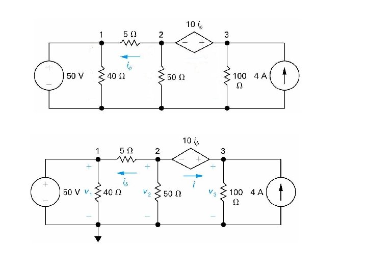
4. 3 The Node-Voltage Method and Dependent Sources If the circuit contains dependent source, the node-voltage equations must be supplemented with the constraint equations imposed by the dependent source as will be shown in the example next Example 4. 3 Use the node voltage method to find the power dissipated in the 5 W resistor
1 2 3 3 The circuit has three essentials nodes 1, 2, and 3 and one of them will be the reference We select node 3 as the reference node since it has the most branches (i. e, 4 branches) We need two node-voltage equations to describe the circuit
20 v 1 v 2 The circuit has two non essentials nodes which are connected to voltage sources and will impose the constrain imposed by the value of the voltage sources on the non essential nodes voltage Applying KCL at node 1 Applying KCL at node 2
20 v 1 The second node equation contain the current v 2 if which is related to the nodes voltages as Substituting in the second node equation, we have the following nodes equations Solving we have
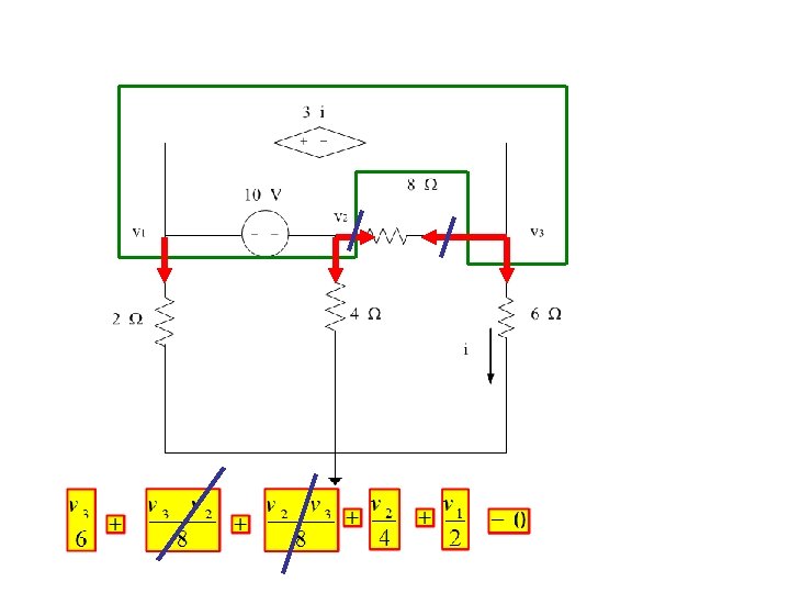
4. 4 The Node-Voltage Method : Some Special Cases Let us consider the following circuit 1 2 3 3 The circuit has three essentials nodes 1, 2, and 3 which means that two simultaneous equations are needed. From the three essentials nodes, a reference node has been chosen and the other two nodes have been labeled
100 v 1 v 2 However since the 100 V source constrains the voltage between node 1 and the reference node to 100 V. This mean that there is only one unknown node voltage namely (v 2) Applying KCL at node 2 Since Knowing v 1 and v 2 we can calculate the current in every branch
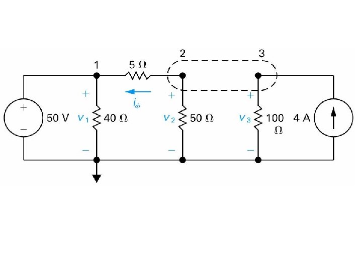
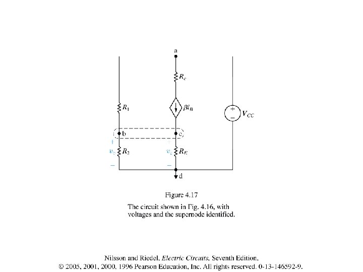
Nodal Analysis with voltage sources Some Special Cases This voltage source is connected between non reference and reference
This voltage source is connected between two non reference nodes reference
Enclose the voltage source in a region called supper node Apply KCL to that region
KCL on the Supper node
KCL on the Supper node The second equation come from the constraint on the voltage source Two equations and two unknowns , we can solve
Two voltage sources are connected between two non reference nodes reference
Two supper nodes touching or intersection
Dependent Voltage source supper node apply as will to dependent sources
Combine the two supper nodes to supper node
4. 5 Introduction to the Mesh-Current Method Consider the following planar circuit There are 4 essentials nodes
There are 7 essentials branches were the current is unknown Therefore to solve via the mesh-current method we must write 4 mesh -current
A mesh current is the current that exists only in the perimeter of a mesh as shown in the circuit below The mesh current satisfy Kirchhoff’s Current Law (KCL) At any node in the circuit, a given mesh current both enters and leaves the node Mesh current is not always equal branch current
Mesh current is not always equal branch current The branch current Equal the mesh current The branch current Doesn't equal any of the mesh currents
Consider the following circuit were we want to solve for the currents The circuit has 3 essential branches and 2 essentials nodes Therefore to solve via the mesh-current method we must write 2 mesh -current
Applying KCL to the upper node (one KCL for two essentials nodes) Applying KVL around the two meshes Solving the KCL for i 3 and substituting in the KVL equations we have
Now consider the mesh currents ia, ib , and applying KVL around the two meshes we have The two equations are identical if we replace the currents i 1, i 2 with the mesh currents ia, ib
the branches currents i 1, i 2, i 3 can be written in terms of the mesh currents ia, ib Once we solve for the mesh current we can solve for any branch current Once we know the branch current we can solve for any voltage or power of interest current
Example 4. 4
4. 6 The mesh-Current Method and dependent sources Example 4. 5 Use the mesh-current method to determine the power dissipated in the 4 W resistor
KVL on mesh 1 KVL on mesh 2 KVL on mesh 3
we need only i 2 and i 3 To solve, we use Cramer method as follows,
4. 7 The Mesh-Current Method : Some Special Cases
Supermesh
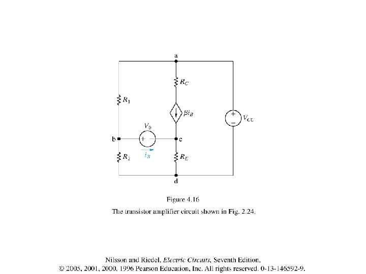
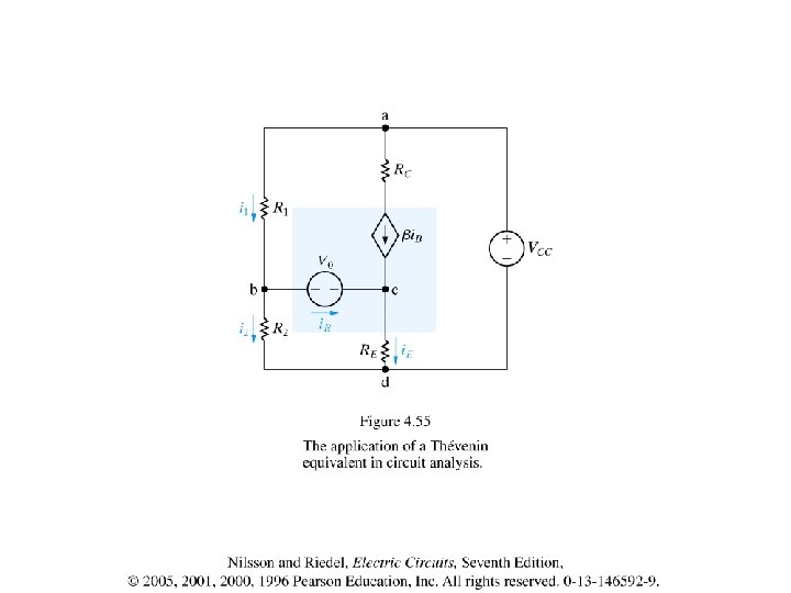
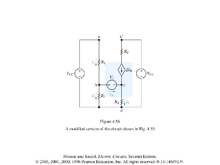
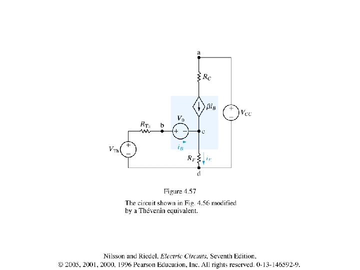
The Mesh-Current Analysis of the Amplifier Circuit
Supermesh
4. 8 The Node-Voltage Method Versus the Mesh-Current Method
Supernode
Supernode
Supermesh
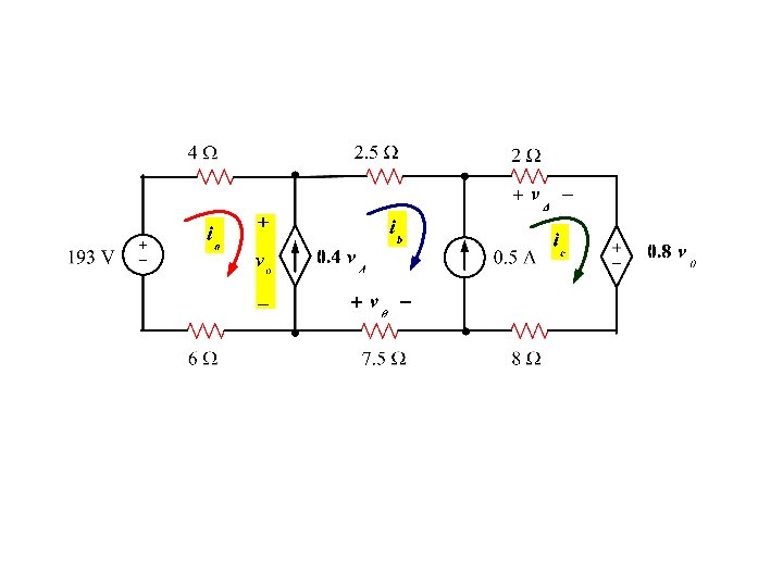
By inspection 193
4. 9 Source Transformations The Node-Voltage Method and the Mesh-Current Method are powerful techniques for solving circuits. We are still interested in in methods that can be used to simplify circuits like to what we did in parallel and series resistors and D to Y transformations A method called Source Transformations will allow the transformations of a voltage source in series with a resistor to a current source in parallel with resistor. The double arrow indicate that the transformation is bilateral , that we can start with either configuration and drive the other
Equating we have ,
Example 4. 8 (a) find the power associated with the 6 V source (b) State whether the 6 V source is absorbing or delivering power We are going to use source transformation to reduce the circuit, however note that we will not alter or transfer the 6 V source because it is the objective.
It should be clear if we transfer the 6 V during these steps you will not be able to find the power associated with it
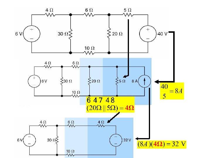
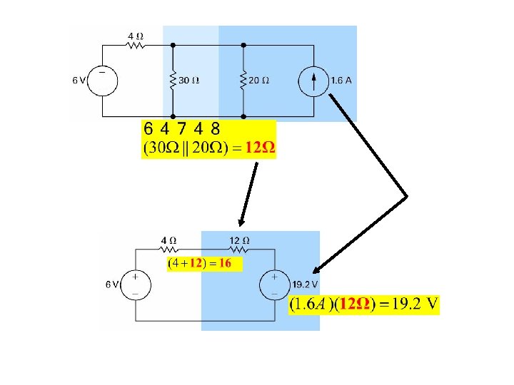
Example 4. 9 (a) use source transformations to find the voltage vo ? Since the 125 W resistor is connected across or in parallel to the 250 V source then we can remove it without altering any voltage or current on the circuit except the 250 V current which is not an objective any how Our objective is vo Therefore we remove the 125 W Similarly the 10 W resistor is connected in series with the 8 A source then we can remove it without altering any voltage or current on the circuit
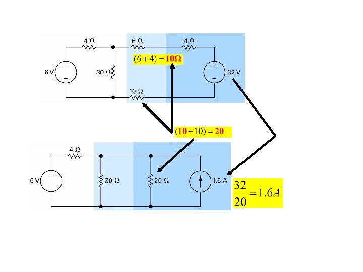
Now the circuit become We now use the source transformation to replace the 250 V with the 25 W resistor with a current source and parallel resistor We now combine the parallel resistors
We now combine the parallel resistors The circuit now become
Let us find the Thevenin Equivalent of the following circuit By inspection 25 Therefore the Thevenin voltage for the circuit is 32 V
To find the RTh we deactivate the sources by shortening independent voltage sources and open independent current source
Let us find the Thevenin Equivalent using source transformations
The Thevenin Equivalent is represented as an independent voltage source VTh and a series resistor RTh Now let us put a short across the terminal and calculate the resulting current And this another method of finding RTh as
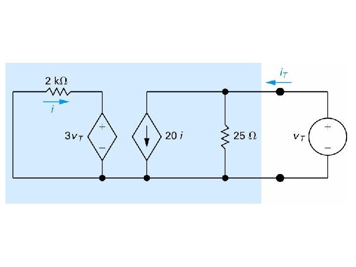
Let us find the 25 i. SC for the circuit shown before By inspection i. SC can be found easily once we know the voltage v 2 To find v 2 select the reference as the lower node and write KCL
Norton Equivalent
4. 64 Find Thevenini equivalent with respect to the terminals A Using short circuit current B Deactivating the independent sources and
A Using short circuit current
17. 4
B Deactivating the independent sources
4. 12 Maximum Power Transfer Question : what is the value of the load resistant RL that will absorb the maximum power
Substituting in
4. 13 Superposition A linear system obeys the principle of superposition which state that : Whenever a linear system is excited or driven by more than one independent source of energy , the total response is the sum of the individual responses by the independent sources Example Consider the following linear circuit We will use the principle of superposition to find the branch currents
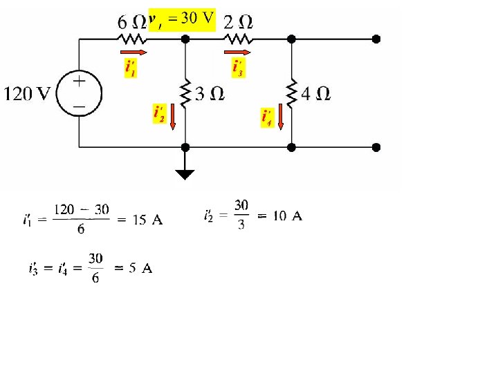
1 - Voltage Source is active and deactivate the current source by opening it KCL at node
2 - Current Source is active and deactivate the voltage source by shorting it Using Nodal analysis Solving we get
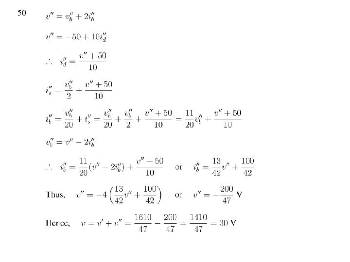
Now to find the branch currents We sum the currents
P 488 Use the principle of superposition to find the voltage v in the circuit
70 -V Source acting alone 70 1 2 3 Therefore from 2 and 3 we have 4 Since From 4 Therefore from 1 and 5 we have 5 OR OR