Chapter 4 Sequential Circuits 4 1 Sequential Circuit


: a buffer • t. G the delay • the information")


 latch Fig. 4 -8")

 Fig. 5 -11")


")
: for Fig. 4 -13 (b): for Fig. 4 -14")

- Slides: 21
Chapter 4 Sequential Circuits
4 -1 Sequential Circuit Definitions • Combinational Circuits + Storage element • output depends both on previous state and input Fig. 4 -1
Storage element • (a): a buffer • t. G the delay • the information enters the buffer at t and output at t+ t. G • the stored information only retained in buffer by t. G • longer storage time is necessary in most applications Fig. 4 -2
Synchronous clocked sequential circuit Use flip-flop Fig. 4 -3
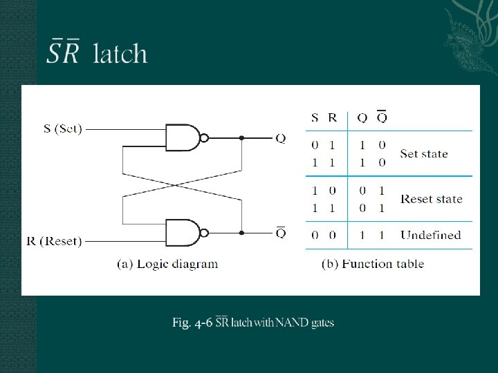
4 -2 latch • A storage element can maintain a binary state indefinitely, until directed by an input signal to switch states. • The most basic storage elements are latches. Fig. 4 -4 SR latch with NOR gates
Simulation for SR latch Fig. 5 -5
latch with control input Fig. 4 -7
D (Data) latch Fig. 4 -8
4 -3 Flip-Flops A change in value on the control input allows the state of a latch in a flip-flop to switch. This change is called a trigger The trigger enable (trigger) the flip-flops See Fig. 4 -3 for sequential circuits A present (original) and next (new) state occur in flipflop before and after the trigger, respectively The most important element in sequential circuits Can be derived from latch
Edge-trigger Flip-Flop Negative-edge-trigger Flip-Flop (Master-Slave flip-flop) Fig. 5 -11
Edge-trigger Flip Flop Positive -edge-trigger Flip-Flop
Symbols Fig. 5 -13
Symbols Fig. 4 -12
4 -4 Sequential Circuit Analysis The output and the next state are a function of the inputs and the present state. An example input equations output equation Fig. 4 -13 15
State table
Two-dimensional state table
Mealy model/Moore model Mealy model circuits Sequential circuits in which the outputs depend on the input, as well as on the states The circuits in Fig. 4 -13 Moore model circuits Sequential circuits in which the outputs depend only on the states The circuits in Fig. 4 -14
A Moore model circuit (Fig. 4 -14)
State diagram (a): for Fig. 4 -13 (b): for Fig. 4 -14
Sequential Circuit Simulation A simulator for the input/output of a designed circuit Functional simulation Timing simulation