
Chapter 4 Network Layer 4 b Routing Modified
Chapter 4 Network Layer (4 b - Routing) Modified by John Copeland Georgia Tech for use in ECE 3600 A note on the use of these ppt slides: We’re making these slides freely available to all (faculty, students, readers). They’re in Power. Point form so you can add, modify, and delete slides (including this one) and slide content to suit your needs. They obviously represent a lot of work on our part. In return for use, we only ask the following: q If you use these slides (e. g. , in a class) in substantially unaltered form, that you mention their source (after all, we’d like people to use our book!) q If you post any slides in substantially unaltered form on a www site, that you note that they are adapted from (or perhaps identical to) our slides, and note our copyright of this material. Thanks and enjoy! JFK/KWR All material copyright 1996 -2006 J. F Kurose and K. W. Ross, All Rights Reserved JAC 10 -8 -2013 Computer Networking: A Top Down Approach Featuring the Internet, 5 th edition. Jim Kurose, Keith Ross Addison-Wesley, July 2009. Network Layer 4 -1
Chapter 4: Network Layer r 4. 1 Introduction r 4. 2 Virtual circuit and datagram networks r 4. 3 What’s inside a router r 4. 4 IP: Internet Protocol m m Datagram format IPv 4 addressing ICMP IPv 6 r 4. 5 Routing algorithms m Link state (OSPF) m Distance Vector (RIP) m Hierarchical routing (BGP) r 4. 6 Routing in the Internet m m m RIP OSPF BGP r 4. 7 Broadcast and multicast routing Network Layer 4 -2
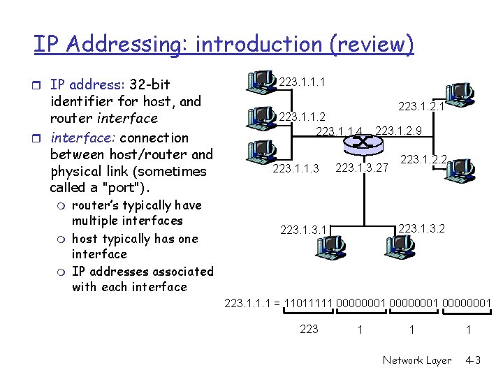
IP Addressing: introduction (review) r IP address: 32 -bit identifier for host, and router interface: connection between host/router and physical link (sometimes called a "port"). m router’s typically have multiple interfaces m host typically has one interface m IP addresses associated with each interface 223. 1. 1. 1 223. 1. 1. 2 223. 1. 1. 4 223. 1. 1. 3 223. 1. 2. 1 223. 1. 2. 9 223. 1. 3. 27 223. 1. 2. 2 223. 1. 1. 1 = 11011111 00000001 223 1 1 Network Layer 1 4 -3
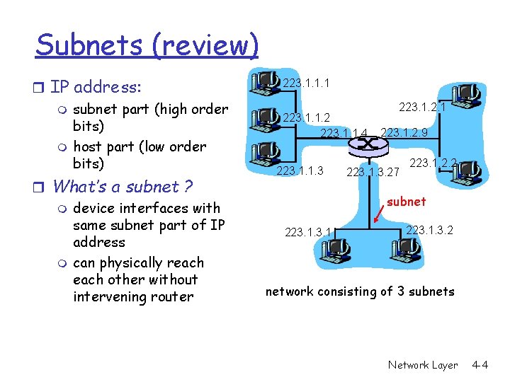
Subnets (review) r IP address: m subnet part (high order bits) m host part (low order bits) r What’s a subnet ? m device interfaces with same subnet part of IP address m can physically reach other without intervening router 223. 1. 1. 1 223. 1. 1. 2 223. 1. 1. 4 223. 1. 1. 3 223. 1. 2. 1 223. 1. 2. 9 223. 1. 3. 27 223. 1. 2. 2 subnet 223. 1. 3. 2 network consisting of 3 subnets Network Layer 4 -4

Subnets (review) Recipe r To determine the subnets, detach each interface from its gateway (default) router, creating islands of isolated networks. Each isolated network is called a subnet. 223. 1. 1. 0/24 223. 1. 2. 0/24 223. 1. 3. 0/24 Subnet mask: /24 Network Layer 4 -5
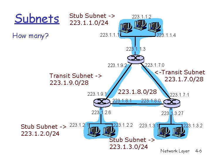
Subnets Stub Subnet -> 223. 1. 1. 0/24 How many? 223. 1. 1. 2 223. 1. 1. 1 223. 1. 1. 4 223. 1. 1. 3 223. 1. 9. 2 223. 1. 7. 0 <-Transit Subnet 223. 1. 7. 0/28 Transit Subnet -> 223. 1. 9. 0/28 223. 1. 8. 0/28 223. 1. 9. 1 223. 1. 8. 0 223. 1. 2. 6 Stub Subnet -> 223. 1. 2. 0/24 223. 1. 2. 1 223. 1. 7. 1 223. 1. 3. 27 223. 1. 2. 2 223. 1 Stub Subnet -> 223. 1. 3. 0/24 223. 1. 3. 2 Network Layer 4 -6
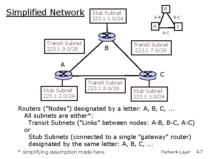
Simplified Network Stub Subnet 223. 1. 1. 0/24 B A-B B-C A C A-C Transit Subnet 223. 1. 9. 0/28 B Transit Subnet 223. 1. 7. 0/28 A C Stub Subnet 223. 1. 2. 0/24 Transit Subnet 223. 1. 8. 0/28 Stub Subnet 223. 1. 3. 0/24 Routers ("Nodes") designated by a letter: A, B, C, . . . All subnets are either*: Transit Subnets ("Links" between nodes: A-B, B-C, A-C) or Stub Subnets (connected to a single "gateway" router) designated by the same letter: A, B, C, . . . * simplifying assumption made here. Network Layer 4 -7
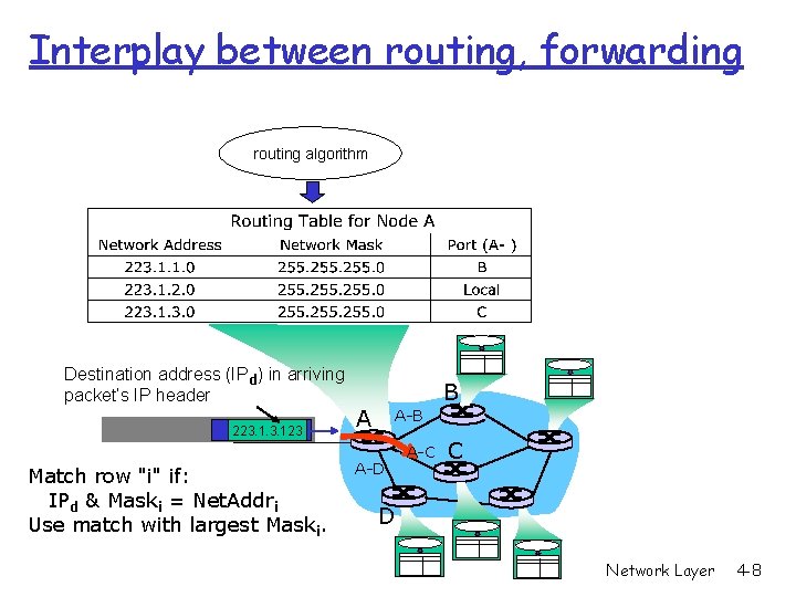
Interplay between routing, forwarding routing algorithm Destination address (IPd) in arriving packet’s IP header 223. 123 Match row "i" if: IPd & Maski = Net. Addri Use match with largest Maski. A B A-B 1 3 2 A-D A-C C D Network Layer 4 -8
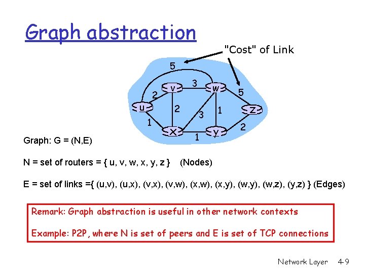
Graph abstraction "Cost" of Link 5 2 u 2 1 Graph: G = (N, E) v x N = set of routers = { u, v, w, x, y, z } 3 w 3 1 5 z 1 y 2 (Nodes) E = set of links ={ (u, v), (u, x), (v, w), (x, y), (w, z), (y, z) } (Edges) Remark: Graph abstraction is useful in other network contexts Example: P 2 P, where N is set of peers and E is set of TCP connections Network Layer 4 -9
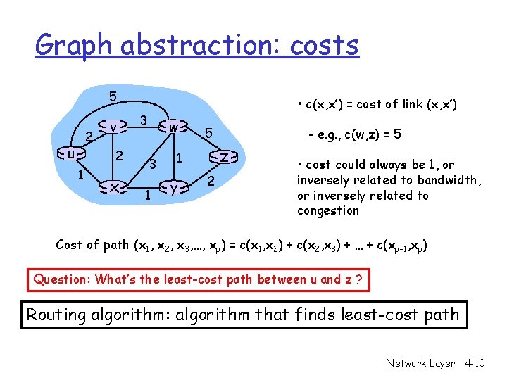
Graph abstraction: costs 5 2 u v 2 1 x • c(x, x’) = cost of link (x, x’) 3 w 3 1 5 z 1 y - e. g. , c(w, z) = 5 2 • cost could always be 1, or inversely related to bandwidth, or inversely related to congestion Cost of path (x 1, x 2, x 3, …, xp) = c(x 1, x 2) + c(x 2, x 3) + … + c(xp-1, xp) Question: What’s the least-cost path between u and z ? Routing algorithm: algorithm that finds least-cost path Network Layer 4 -10
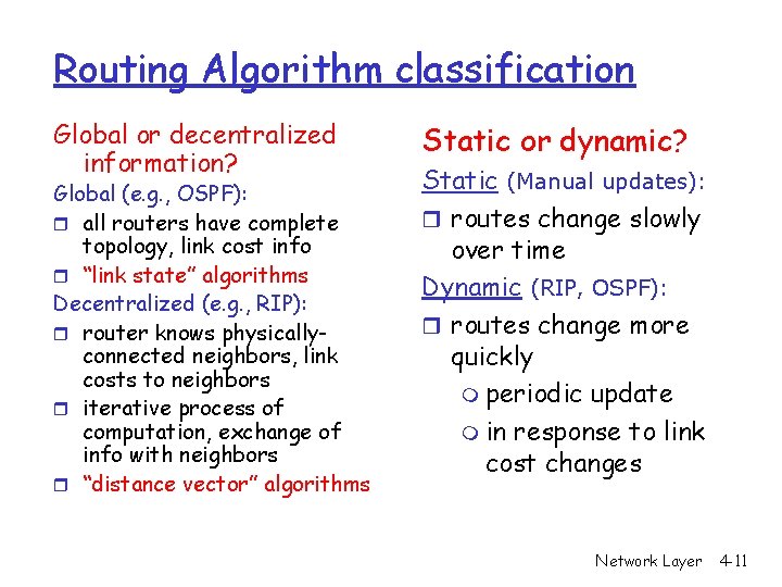
Routing Algorithm classification Global or decentralized information? Global (e. g. , OSPF): r all routers have complete topology, link cost info r “link state” algorithms Decentralized (e. g. , RIP): r router knows physicallyconnected neighbors, link costs to neighbors r iterative process of computation, exchange of info with neighbors r “distance vector” algorithms Static or dynamic? Static (Manual updates): r routes change slowly over time Dynamic (RIP, OSPF): r routes change more quickly m periodic update m in response to link cost changes Network Layer 4 -11
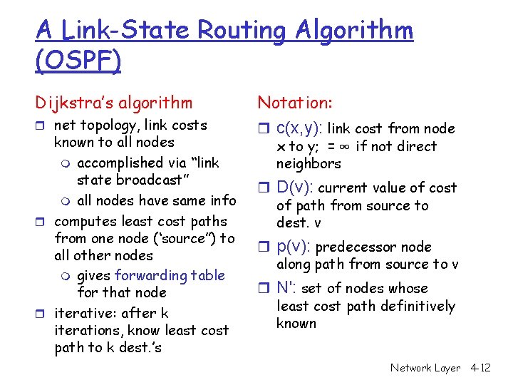
A Link-State Routing Algorithm (OSPF) Dijkstra’s algorithm r net topology, link costs known to all nodes m accomplished via “link state broadcast” m all nodes have same info r computes least cost paths from one node (‘source”) to all other nodes m gives forwarding table for that node r iterative: after k iterations, know least cost path to k dest. ’s Notation: r c(x, y): link cost from node x to y; = ∞ if not direct neighbors r D(v): current value of cost of path from source to dest. v r p(v): predecessor node along path from source to v r N': set of nodes whose least cost path definitively known Network Layer 4 -12
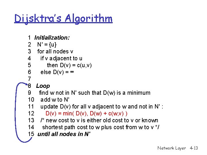
Dijsktra’s Algorithm 1 Initialization: 2 N' = {u} 3 for all nodes v 4 if v adjacent to u 5 then D(v) = c(u, v) 6 else D(v) = ∞ 7 8 Loop 9 find w not in N' such that D(w) is a minimum 10 add w to N' 11 update D(v) for all v adjacent to w and not in N' : 12 D(v) = min( D(v), D(w) + c(w, v) ) 13 /* new cost to v is either old cost to v or known 14 shortest path cost to w plus cost from w to v */ 15 until all nodes in N' Network Layer 4 -13
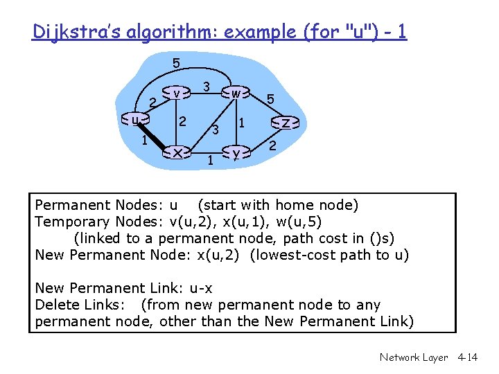
Dijkstra’s algorithm: example (for "u") - 1 5 2 u v 2 1 x 3 w 3 1 5 z 1 y 2 Permanent Nodes: u (start with home node) Temporary Nodes: v(u, 2), x(u, 1), w(u, 5) (linked to a permanent node, path cost in ()s) New Permanent Node: x(u, 2) (lowest-cost path to u) New Permanent Link: u-x Delete Links: (from new permanent node to any permanent node, other than the New Permanent Link) Network Layer 4 -14
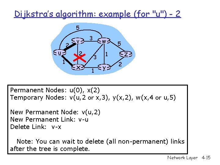
Dijkstra’s algorithm: example (for "u") - 2 5 2 u v 2 1 x 3 w 3 1 5 z 1 y 2 Permanent Nodes: u(0), x(2) Temporary Nodes: v(u, 2 or x, 3), y(x, 2), w(x, 4 or u, 5) New Permanent Node: v(u, 2) New Permanent Link: v-u Delete Link: v-x Note: You can wait to delete (all non-permanent) links after the tree is complete. Network Layer 4 -15
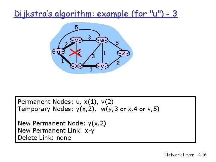
Dijkstra’s algorithm: example (for "u") - 3 5 2 u v 2 1 x 3 w 3 1 5 z 1 y 2 Permanent Nodes: u, x(1), v(2) Temporary Nodes: y(x, 2), w(y, 3 or x, 4 or v, 5) New Permanent Node: y(x, 2) New Permanent Link: x-y Delete Link: none Network Layer 4 -16
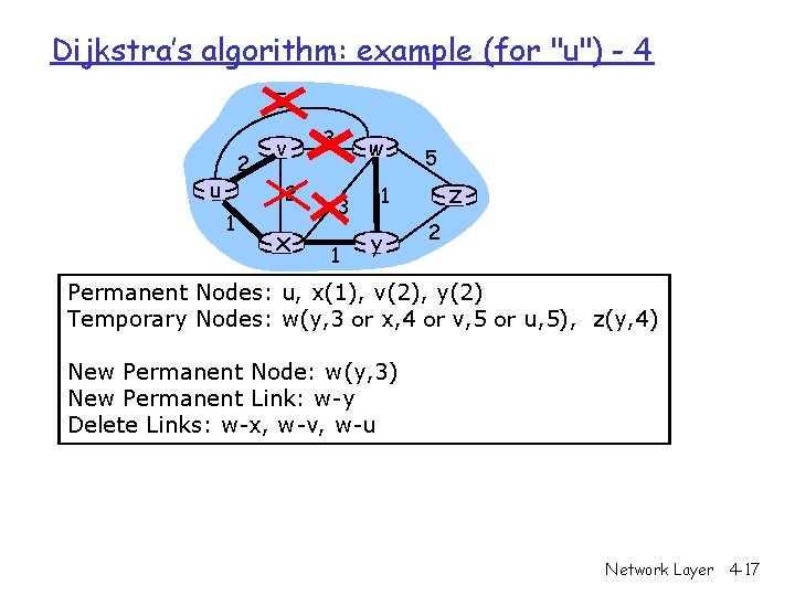
Dijkstra’s algorithm: example (for "u") - 4 5 2 u v 2 1 x 3 w 3 1 5 z 1 y 2 Permanent Nodes: u, x(1), v(2), y(2) Temporary Nodes: w(y, 3 or x, 4 or v, 5 or u, 5), z(y, 4) New Permanent Node: w(y, 3) New Permanent Link: w-y Delete Links: w-x, w-v, w-u Network Layer 4 -17
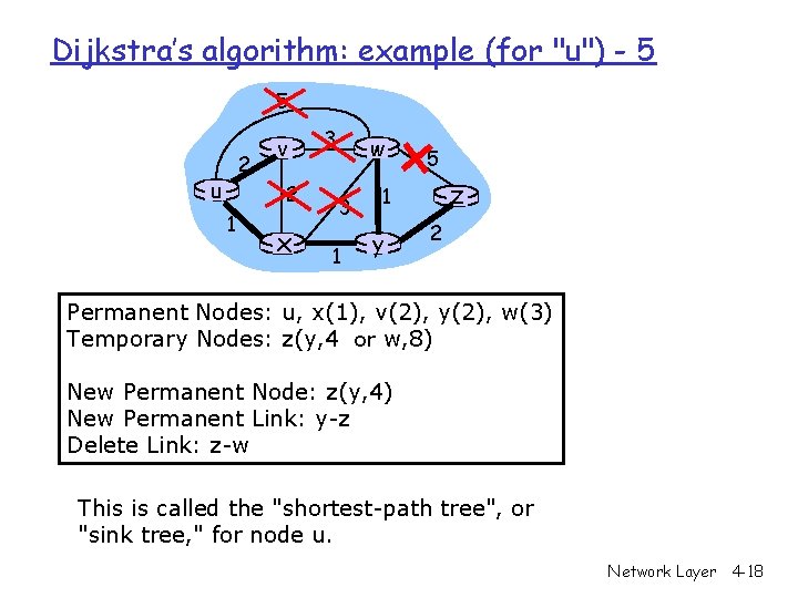
Dijkstra’s algorithm: example (for "u") - 5 5 2 u v 2 1 x 3 w 3 1 5 z 1 y 2 Permanent Nodes: u, x(1), v(2), y(2), w(3) Temporary Nodes: z(y, 4 or w, 8) New Permanent Node: z(y, 4) New Permanent Link: y-z Delete Link: z-w This is called the "shortest-path tree", or "sink tree, " for node u. Network Layer 4 -18
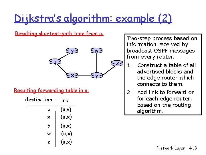
Dijkstra’s algorithm: example (2) Resulting shortest-path tree from u: v w u z x Resulting forwarding table in u: destination link v x (u, v) (u, x) y (u, x) w (u, x) z (u, x) y Two-step process based on information received by broadcast OSPF messages from every router. 1. Construct a table of all advertised blocks and the edge router which connects to them. 2. Add link to forward on for each edge router, based on the routing algorithm. Network Layer 4 -19
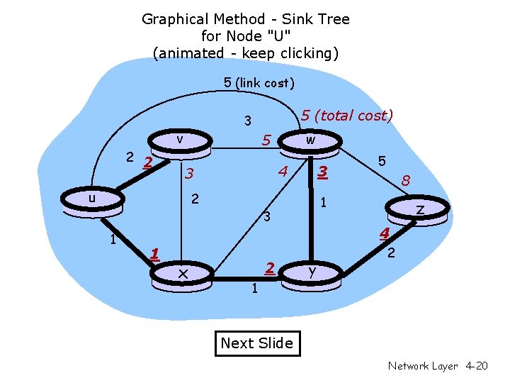
Graphical Method - Sink Tree for Node "U" (animated - keep clicking) 5 (link cost) 2 2 5 (total cost) 3 v w 5 4 3 u 3 2 1 x 2 1 8 1 3 1 5 z 4 y 2 Next Slide Network Layer 4 -20
Chapter 4: Network Layer r 4. 1 Introduction r 4. 2 Virtual circuit and datagram networks r 4. 3 What’s inside a router r 4. 4 IP: Internet Protocol m m Datagram format IPv 4 addressing ICMP IPv 6 r 4. 5 Routing algorithms m Link state (OSPF) m Distance Vector (RIP) m Hierarchical routing r 4. 6 Routing in the Internet m m m RIP OSPF BGP r 4. 7 Broadcast and multicast routing Network Layer 4 -21
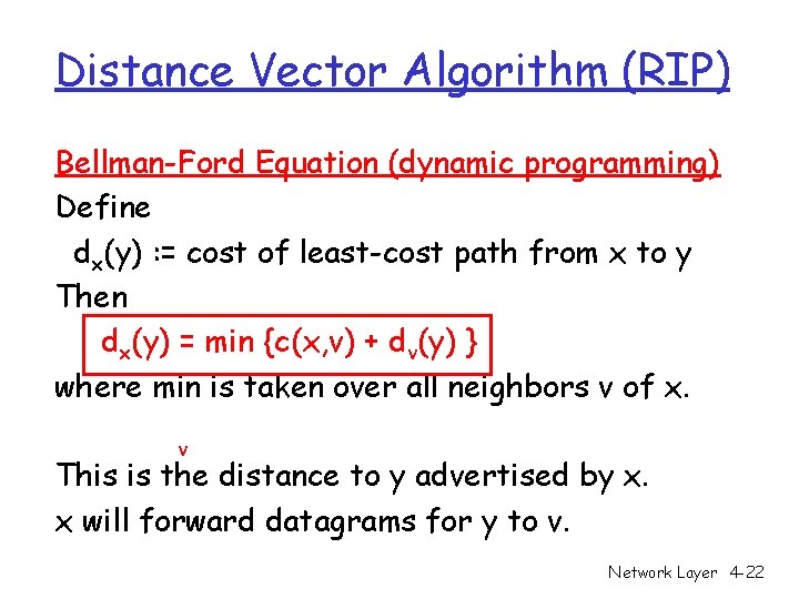
Distance Vector Algorithm (RIP) Bellman-Ford Equation (dynamic programming) Define dx(y) : = cost of least-cost path from x to y Then dx(y) = min {c(x, v) + dv(y) } where min is taken over all neighbors v of x. v This is the distance to y advertised by x. x will forward datagrams for y to v. Network Layer 4 -22
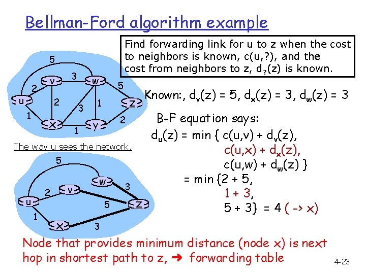
Bellman-Ford algorithm example Find forwarding link for u to z when the cost to neighbors is known, c(u, ? ), and the cost from neighbors to z, d? (z) is known. 5 2 u 3 v 2 1 w 3 x 1 5 z 1 2 y The way u sees the network. 5 2 u 1 v w 5 3 Known: , dv(z) = 5, dx(z) = 3, dw(z) = 3 B-F equation says: du(z) = min { c(u, v) + dv(z), c(u, x) + dx(z), c(u, w) + dw(z) } = min {2 + 5, 1 + 3, z 5 + 3} = 4 ( -> x) x 3 Node that provides minimum distance (node x) is next hop in shortest path to z, ➜ forwarding table. Network Layer 4 -23
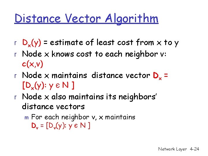
Distance Vector Algorithm r Dx(y) = estimate of least cost from x to y r Node x knows cost to each neighbor v: c(x, v) r Node x maintains distance vector Dx = [Dx(y): y є N ] r Node x also maintains its neighbors’ distance vectors m For each neighbor v, x maintains Dv = [Dv(y): y є N ] Network Layer 4 -24
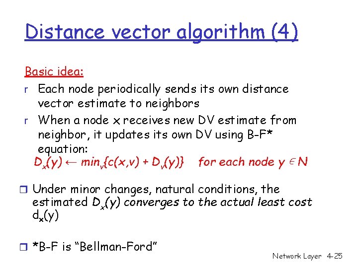
Distance vector algorithm (4) Basic idea: r Each node periodically sends its own distance vector estimate to neighbors r When a node x receives new DV estimate from neighbor, it updates its own DV using B-F* equation: Dx(y) ← minv{c(x, v) + Dv(y)} for each node y ∊ N r Under minor changes, natural conditions, the estimated Dx(y) converges to the actual least cost dx(y) r *B-F is “Bellman-Ford” Network Layer 4 -25
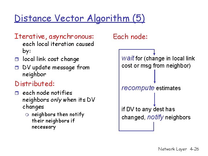
Distance Vector Algorithm (5) Iterative, asynchronous: each local iteration caused by: r local link cost change r DV update message from neighbor Distributed: r each node notifies neighbors only when its DV changes m neighbors then notify their neighbors if necessary Each node: wait for (change in local link cost or msg from neighbor) recompute estimates if DV to any dest has changed, notify neighbors Network Layer 4 -26
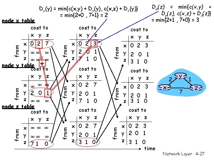
Dx(y) = min{c(x, y) + Dy(y), c(x, z) + Dz(y)} = min{2+0 , 7+1} = 2 node x table cost to x y z x ∞∞ ∞ y ∞∞ ∞ z 71 0 from x 0 2 7 y 2 0 1 z 7 1 0 cost to x y z x 0 2 7 y 2 0 1 z 3 1 0 x 0 2 3 y 2 0 1 z 3 1 0 cost to x y z x 0 2 3 y 2 0 1 z 3 1 0 x 2 y 7 1 z cost to x y z from x ∞ ∞ ∞ y 2 0 1 z ∞∞ ∞ node z table cost to x y z x 0 2 3 y 2 0 1 z 7 1 0 cost to x y z from x 0 2 7 y ∞∞ ∞ z ∞∞ ∞ node y table + cost to x y z Dx(z) = min{c(x, y) + Dy(z), c(x, z) + Dz(z)} = min{2+1 , 7+0} = 3 x 0 2 3 y 2 0 1 z 3 1 0 time Network Layer 4 -27
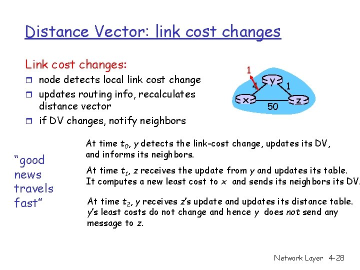
Distance Vector: link cost changes Link cost changes: r node detects local link cost change r updates routing info, recalculates distance vector r if DV changes, notify neighbors “good news travels fast” 1 x 4 y 50 1 z At time t 0, y detects the link-cost change, updates its DV, and informs its neighbors. At time t 1, z receives the update from y and updates its table. It computes a new least cost to x and sends its neighbors its DV. At time t 2, y receives z’s update and updates its distance table. y’s least costs do not change and hence y does not send any message to z. Network Layer 4 -28
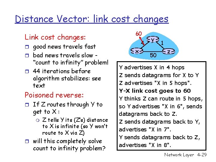
Distance Vector: link cost changes Link cost changes: r good news travels fast r bad news travels slow - “count to infinity” problem! r 44 iterations before algorithm stabilizes: see text Poisoned reverse: r If Z routes through Y to get to X : m Z tells Y its (Z’s) distance to X is infinite (so Y won’t route to X via Z) r will this completely solve count to infinity problem? 60 x 4 y 50 1 z Y advertises X in 4 hops Z sends datagrams for X to Y Z advertises "X in 5 hops". Y-X link cost goes to 60 Y thinks Z can route in 5 hops, so Y advertises "X in 6", sends datagrams back to Z. Z sends datagrams back to Y, advertises "X in 7". Y sends datagrams back to Z, advertises "X in 8". Network Layer 4 -29
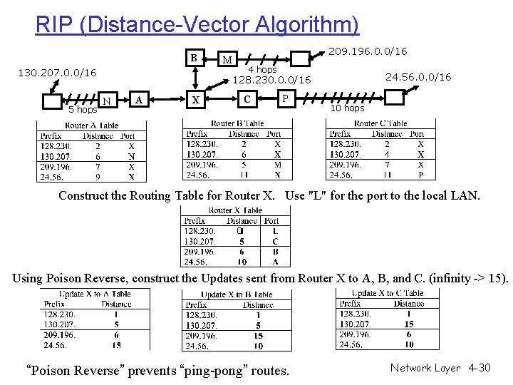
RIP (Distance-Vector Algorithm) B 130. 207. 0. 0/16 5 hops 209. 196. 0. 0/16 M 4 hops 24. 56. 0. 0/16 128. 230. 0. 0/16 N A C X P 10 hops Construct the Routing Table for Router X. Use "L" for the port to the local LAN. 0 Using Poison Reverse, construct the Updates sent from Router X to A, B, and C. (infinity -> 15). “Poison Reverse” prevents “ping-pong” routes. Network Layer 4 -30
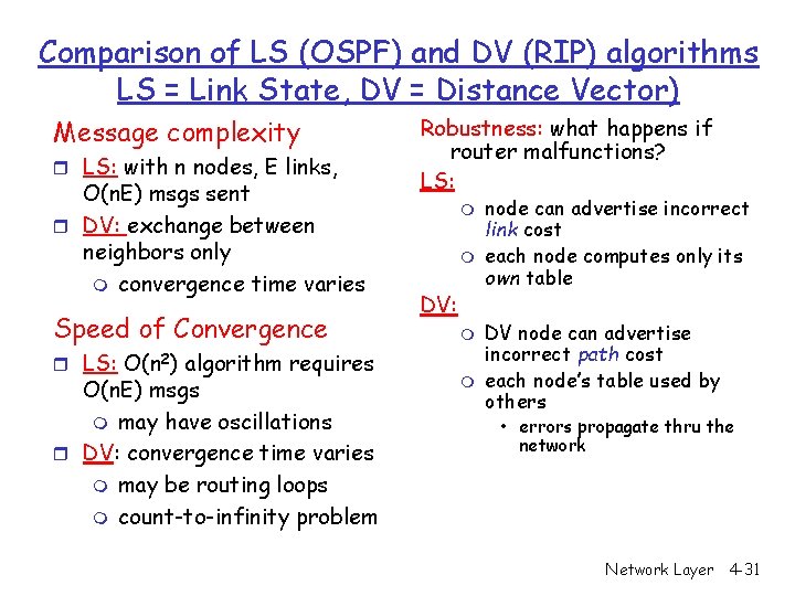
Comparison of LS (OSPF) and DV (RIP) algorithms LS = Link State, DV = Distance Vector) Message complexity r LS: with n nodes, E links, O(n. E) msgs sent r DV: exchange between neighbors only m convergence time varies Speed of Convergence r LS: O(n 2) algorithm requires O(n. E) msgs m may have oscillations r DV: convergence time varies m may be routing loops m count-to-infinity problem Robustness: what happens if router malfunctions? LS: m m DV: m m node can advertise incorrect link cost each node computes only its own table DV node can advertise incorrect path cost each node’s table used by others • errors propagate thru the network Network Layer 4 -31
Chapter 4: Network Layer r 4. 1 Introduction r 4. 2 Virtual circuit and datagram networks r 4. 3 What’s inside a router r 4. 4 IP: Internet Protocol m m Datagram format IPv 4 addressing ICMP IPv 6 r 4. 5 Routing algorithms m Link state m Distance Vector m Hierarchical routing r 4. 6 Routing in the Internet m m m RIP OSPF BGP r 4. 7 Broadcast and multicast routing Network Layer 4 -32
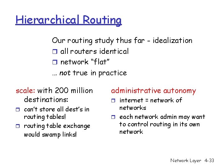
Hierarchical Routing Our routing study thus far - idealization r all routers identical r network “flat” … not true in practice scale: with 200 million destinations: r can’t store all dest’s in routing tables! r routing table exchange would swamp links! administrative autonomy r internet = network of networks r each network admin may want to control routing in its own network Network Layer 4 -33
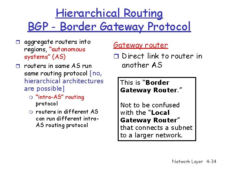
Hierarchical Routing BGP - Border Gateway Protocol r aggregate routers into regions, “autonomous systems” (AS) r routers in same AS run same routing protocol [no, hierarchical architectures are possible] m m “intra-AS” routing protocol routers in different AS can run different intra. AS routing protocol Gateway router r Direct link to router in another AS This is “Border Gateway Router. ” Not to be confused with the “Local Gateway Router” that connects a subnet to a larger network. Network Layer 4 -34
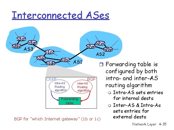
Interconnected ASes 3 c 3 a 3 b AS 3 1 a 2 a 1 c 1 b 1 d 2 c AS 2 AS 1 OSPF r Forwarding table is BGP Intra-AS Routing algorithm 2 b Inter-AS Routing algorithm Forwarding table BGP for “which Internet gateway” (1 b or 1 c) configured by both intra- and inter-AS routing algorithm m m Intra-AS sets entries for internal dests Inter-AS & Intra-As sets entries for external dests Network Layer 4 -35
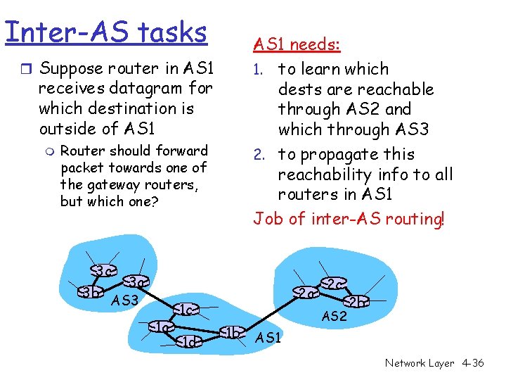
Inter-AS tasks AS 1 needs: 1. to learn which dests are reachable through AS 2 and which through AS 3 2. to propagate this reachability info to all routers in AS 1 Job of inter-AS routing! r Suppose router in AS 1 receives datagram for which destination is outside of AS 1 m Router should forward packet towards one of the gateway routers, but which one? 3 c 3 a 3 b AS 3 1 a 2 a 1 c 1 d 1 b 2 c AS 2 2 b AS 1 Network Layer 4 -36
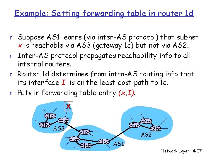
Example: Setting forwarding table in router 1 d r Suppose AS 1 learns (via inter-AS protocol) that subnet x is reachable via AS 3 (gateway 1 c) but not via AS 2. r Inter-AS protocol propagates reachability info to all internal routers. r Router 1 d determines from intra-AS routing info that its interface I is on the least cost path to 1 c. r Puts in forwarding table entry (x, I). X 3 c 3 a 3 b AS 3 1 a 2 a 1 c 1 d 1 b 2 c AS 2 2 b AS 1 Network Layer 4 -37
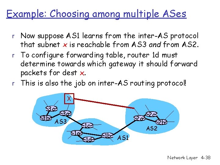
Example: Choosing among multiple ASes r Now suppose AS 1 learns from the inter-AS protocol that subnet x is reachable from AS 3 and from AS 2. r To configure forwarding table, router 1 d must determine towards which gateway it should forward packets for dest x. r This is also the job on inter-AS routing protocol! X 3 c 3 a 3 b AS 3 1 a 2 a 1 c 1 d 1 b 2 c AS 2 2 b AS 1 Network Layer 4 -38
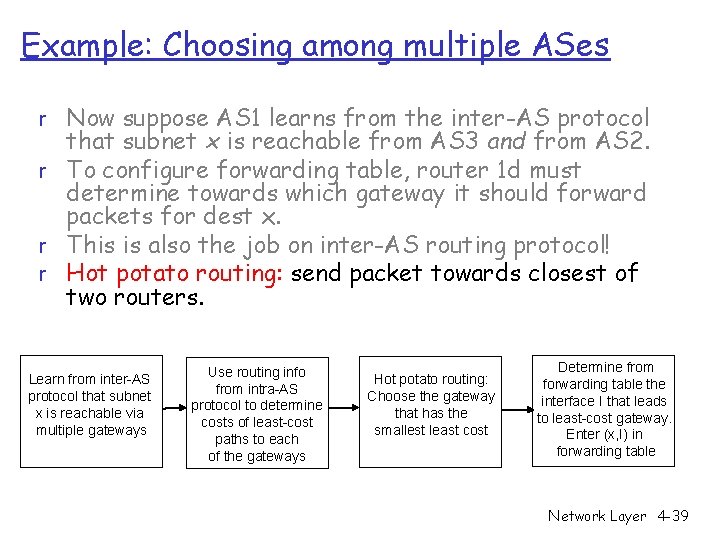
Example: Choosing among multiple ASes r Now suppose AS 1 learns from the inter-AS protocol that subnet x is reachable from AS 3 and from AS 2. r To configure forwarding table, router 1 d must determine towards which gateway it should forward packets for dest x. r This is also the job on inter-AS routing protocol! r Hot potato routing: send packet towards closest of two routers. Learn from inter-AS protocol that subnet x is reachable via multiple gateways Use routing info from intra-AS protocol to determine costs of least-cost paths to each of the gateways Hot potato routing: Choose the gateway that has the smallest least cost Determine from forwarding table the interface I that leads to least-cost gateway. Enter (x, I) in forwarding table Network Layer 4 -39
Chapter 4: Network Layer r 4. 1 Introduction r 4. 2 Virtual circuit and datagram networks r 4. 3 What’s inside a router r 4. 4 IP: Internet Protocol m m Datagram format IPv 4 addressing ICMP IPv 6 r 4. 5 Routing algorithms m Link state m Distance Vector m Hierarchical routing r 4. 6 Routing in the Internet m m m RIP OSPF BGP r 4. 7 Broadcast and multicast routing Network Layer 4 -40
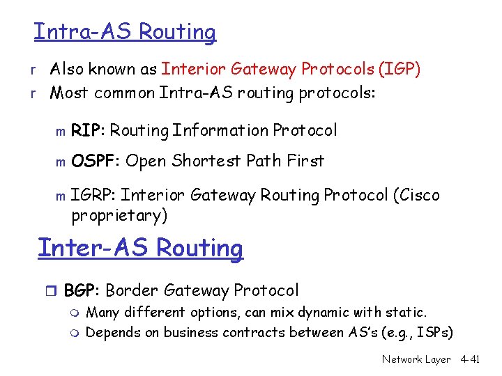
Intra-AS Routing r Also known as Interior Gateway Protocols (IGP) r Most common Intra-AS routing protocols: m RIP: Routing Information Protocol m OSPF: Open Shortest Path First m IGRP: Interior Gateway Routing Protocol (Cisco proprietary) Inter-AS Routing r BGP: Border Gateway Protocol m Many different options, can mix dynamic with static. m Depends on business contracts between AS’s (e. g. , ISPs) Network Layer 4 -41
Chapter 4: Network Layer r 4. 1 Introduction r 4. 2 Virtual circuit and datagram networks r 4. 3 What’s inside a router r 4. 4 IP: Internet Protocol m m Datagram format IPv 4 addressing ICMP IPv 6 r 4. 5 Routing algorithms m Link state m Distance Vector m Hierarchical routing r 4. 6 Routing in the Internet m m m RIP (Distance Vector) OSPF (Link State) BGP (Hierarchical) r 4. 7 Broadcast and multicast routing Network Layer 4 -42
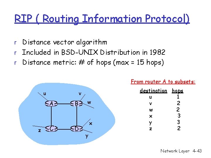
RIP ( Routing Information Protocol) r Distance vector algorithm r Included in BSD-UNIX Distribution in 1982 r Distance metric: # of hops (max = 15 hops) From router A to subsets: u v A z C B D w x y destination hops u 1 v 2 w 2 x 3 y 3 z 2 Network Layer 4 -43
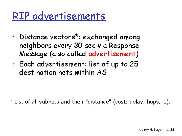
RIP advertisements r Distance vectors*: exchanged among neighbors every 30 sec via Response Message (also called advertisement) r Each advertisement: list of up to 25 destination nets within AS * List of all subnets and their "distance" (cost: delay, hops, …). Network Layer 4 -44
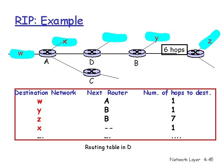
RIP: Example y x w A z 6 hops D B C Destination Network w y z x …. Next Router Num. of hops to dest. …. . . A B B -- 1 1 7 1 Routing table in D Network Layer 4 -45
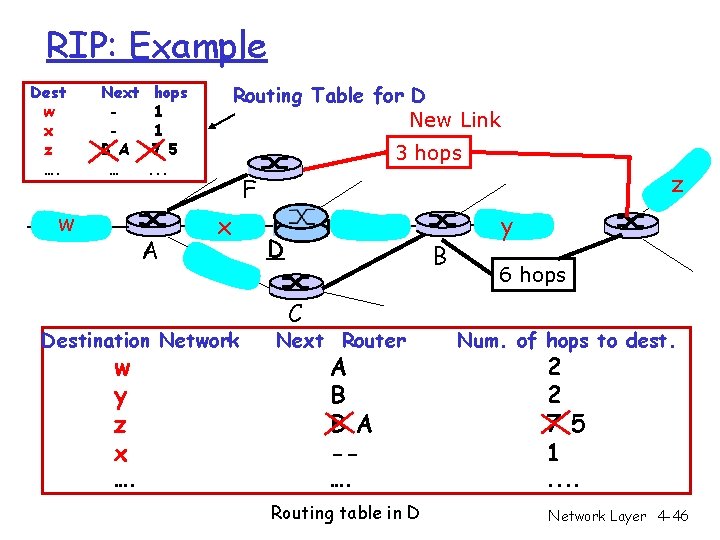
RIP: Example Dest w x z …. Next B A … w Routing Table for D New Link hops 1 1 7 5. . . A 3 hops x Destination Network w y z x …. z F D B C y 6 hops Next Router Num. of hops to dest. …. . . A B B A -- Routing table in D 2 2 7 5 1 Network Layer 4 -46
RIP: Link Failure and Recovery If no advertisement heard after 180 sec --> neighbor/link declared dead m routes via neighbor invalidated m new advertisements sent to neighbors m neighbors in turn send out new advertisements (if tables changed) m link failure info quickly (? ) propagates to entire net m poison reverse used to prevent ping-pong loops (infinite distance = 15 hops) Network Layer 4 -47
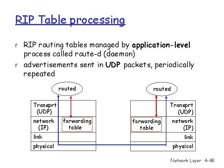
RIP Table processing r RIP routing tables managed by application-level process called route-d (daemon) r advertisements sent in UDP packets, periodically repeated routed Transprt (UDP) network (IP) link physical Transprt (UDP) forwarding table network (IP) link physical Network Layer 4 -48
Chapter 4: Network Layer r 4. 1 Introduction r 4. 2 Virtual circuit and datagram networks r 4. 3 What’s inside a router r 4. 4 IP: Internet Protocol m m Datagram format IPv 4 addressing ICMP IPv 6 r 4. 5 Routing algorithms m Link state m Distance Vector m Hierarchical routing r 4. 6 Routing in the Internet m m m RIP OSPF BGP r 4. 7 Broadcast and multicast routing Network Layer 4 -49
OSPF (Open Shortest Path First) r “open”: publicly available r Uses Link State algorithm m Link State packet dissemination m Topology map at each node m Route computation using Dijkstra’s algorithm r OSPF advertisement carries one entry per neighbor router (OSPF has it’s own Transport Layer Protocol) r Advertisements disseminated to entire AS (via flooding) [exception – Hierarchical Routing] m Carried in OSPF messages directly over IP (rather than TCP or UDP Network Layer 4 -50
OSPF “advanced” features (not in RIP) r Security: all OSPF messages authenticated (to r r prevent malicious intrusion) Multiple same-cost paths allowed (only one path in RIP) For each link, multiple cost metrics for different TOS* (e. g. , satellite link cost set “low” for best effort; high for real time) Integrated uni- and multicast support: m Multicast OSPF (MOSPF) uses same topology data base as OSPF Hierarchical OSPF in large domains. Network Layer 4 -51
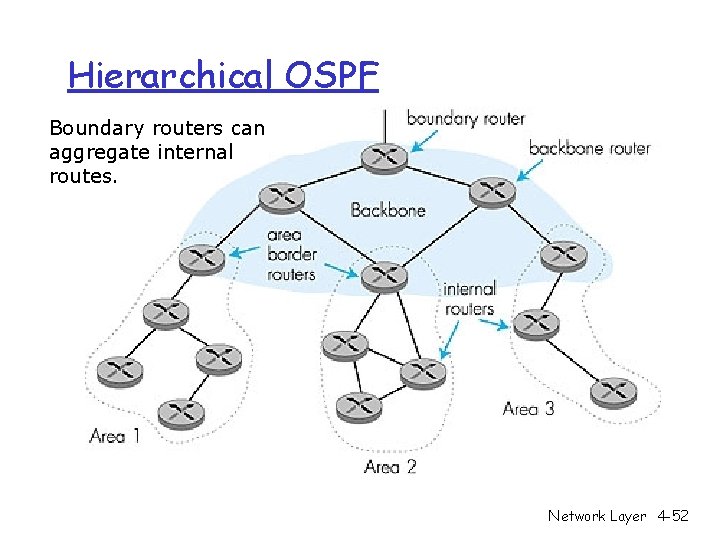
Hierarchical OSPF Boundary routers can aggregate internal routes. Network Layer 4 -52
Hierarchical OSPF r Two-level hierarchy: local area, backbone. Link-state advertisements only in area m each nodes has detailed area topology; only know direction (shortest path) to nets in other areas. r Area border routers: “summarize” distances to nets in own area, advertise to other Area Border routers. r Backbone routers: run OSPF routing limited to backbone. r Boundary routers: connect to other AS’s. m Network Layer 4 -53
Chapter 4: Network Layer r 4. 1 Introduction r 4. 2 Virtual circuit and datagram networks r 4. 3 What’s inside a router r 4. 4 IP: Internet Protocol m m Datagram format IPv 4 addressing ICMP IPv 6 r 4. 5 Routing algorithms m Link state m Distance Vector m Hierarchical routing r 4. 6 Routing in the Internet m m m RIP OSPF BGP r 4. 7 Broadcast and multicast routing Network Layer 4 -54
Internet inter-AS routing: BGP r BGP (Border Gateway Protocol): the de facto standard r BGP provides each AS a means to: 1. 2. 3. Obtain subnet reachability information from neighboring ASs. Propagate reachability information to all ASinternal routers. Determine “good” routes to subnets based on reachability information and policy. r allows subnet to advertise its existence to rest of Internet: “I (130. 207. 0. 0/16) am here” Network Layer 4 -55
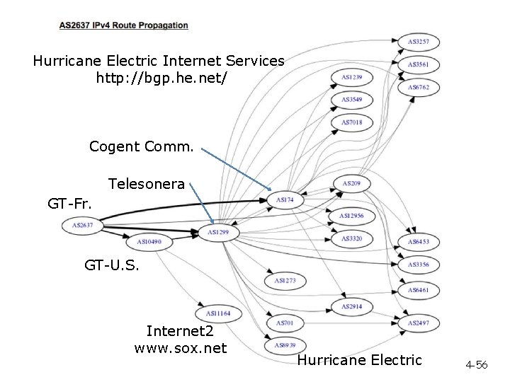
Hurricane Electric Internet Services http: //bgp. he. net/ Cogent Comm. Telesonera GT-Fr. GT-U. S. Internet 2 www. sox. net Hurricane Electric 4 -56
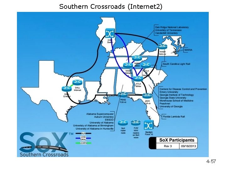
Southern Crossroads (Internet 2) 4 -57
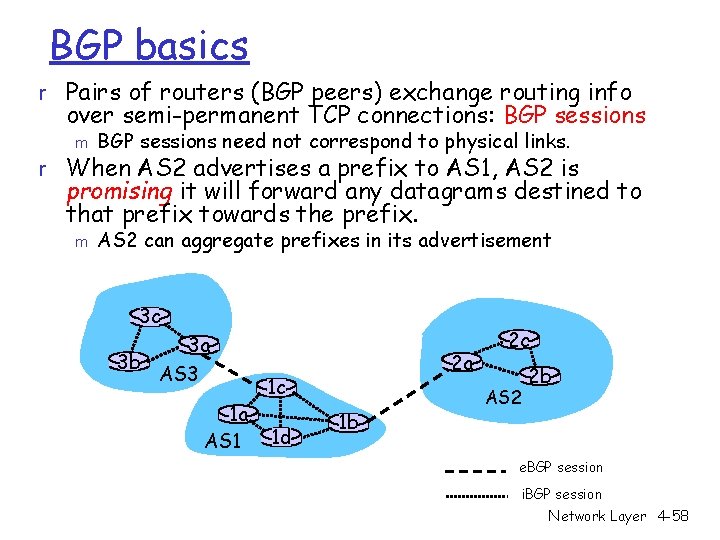
BGP basics r Pairs of routers (BGP peers) exchange routing info over semi-permanent TCP connections: BGP sessions m BGP sessions need not correspond to physical links. r When AS 2 advertises a prefix to AS 1, AS 2 is promising it will forward any datagrams destined to that prefix towards the prefix. m AS 2 can aggregate prefixes in its advertisement 3 c 3 a 3 b AS 3 1 a AS 1 2 a 1 c 1 d 1 b 2 c AS 2 2 b e. BGP session i. BGP session Network Layer 4 -58
Path attributes & BGP routes r When advertising a prefix, advert includes BGP attributes. m prefix + attributes = “route” r When gateway router receives route advertisement, uses import policy to accept/decline. Network Layer 4 -59
BGP route selection r r Router may learn about more than 1 route to some prefix. Router must select route. Elimination rules: 1. 2. 3. 4. Local preference value attribute: policy decision Shortest AS-PATH Closest NEXT-HOP router: hot potato routing Additional criteria Network Layer 4 -60
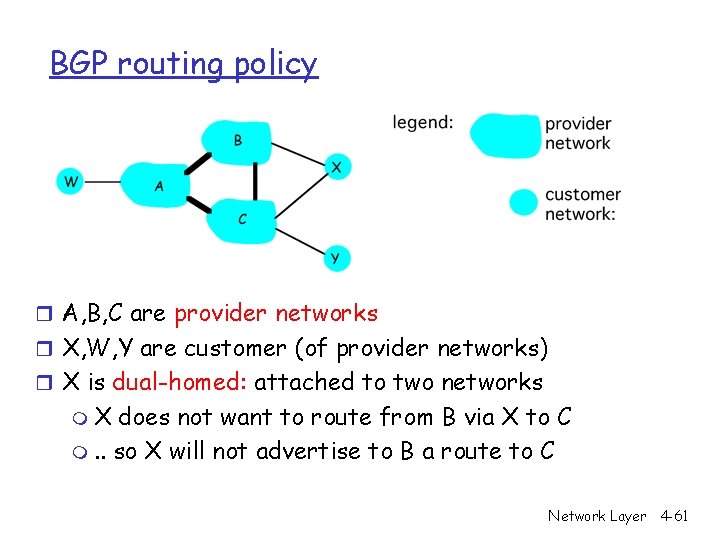
BGP routing policy r A, B, C are provider networks r X, W, Y are customer (of provider networks) r X is dual-homed: attached to two networks m. X does not want to route from B via X to C m. . so X will not advertise to B a route to C Network Layer 4 -61
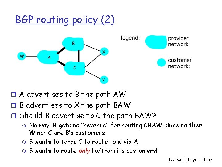
BGP routing policy (2) r A advertises to B the path AW r B advertises to X the path BAW r Should B advertise to C the path BAW? m No way! B gets no “revenue” for routing CBAW since neither W nor C are B’s customers m B wants to force C to route to w via A m B wants to route only to/from its customers! Network Layer 4 -62
Why different Intra- and Inter-AS routing ? Policy: r Inter-AS: admin wants control over how its traffic routed, who routes through its net. r Intra-AS: single admin, so no policy decisions needed Scale: r hierarchical routing saves table size, reduced update traffic Performance: r Intra-AS: can focus on performance r Inter-AS: policy may dominate over performance Network Layer 4 -63
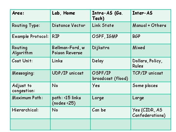
Area: Lab, Home Intra-AS (Ga. Tech) Inter-AS Routing Type: Distance Vector Link State Manual + Others Example Protocol: RIP OSPF, IGMP BGP Routing Algorithm Bellman-Ford, w Poison Reverse Dijkstra Mixed Cost Unit: Links Delay Dollars, Policy, Rules Messaging: UDP/IP unicast OSPF/IP broadcast (flood) TCP/IP unicast Adjust to congestion: No Yes Some places Maximum Path: path: <15 links (nodes <25) Large Hierarchical: No Can be Yes (CIDR, AS Confederations) 4 -64
Chapter 4: Network Layer r 4. 1 Introduction r 4. 2 Virtual circuit and datagram networks r 4. 3 What’s inside a router r 4. 4 IP: Internet Protocol m m Datagram format IPv 4 addressing ICMP IPv 6 r 4. 5 Routing algorithms m Link state m Distance Vector m Hierarchical routing r 4. 6 Routing in the Internet m m m RIP OSPF BGP r 4. 7 Broadcast and multicast routing Network Layer 4 -65
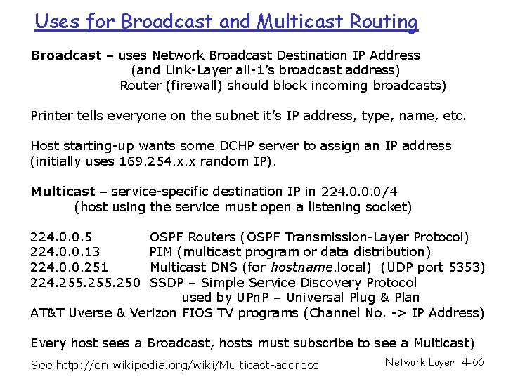
Uses for Broadcast and Multicast Routing Broadcast – uses Network Broadcast Destination IP Address (and Link-Layer all-1’s broadcast address) Router (firewall) should block incoming broadcasts) Printer tells everyone on the subnet it’s IP address, type, name, etc. Host starting-up wants some DCHP server to assign an IP address (initially uses 169. 254. x. x random IP). Multicast – service-specific destination IP in 224. 0. 0. 0/4 (host using the service must open a listening socket) 224. 0. 0. 5 224. 0. 0. 13 224. 0. 0. 251 224. 255. 250 OSPF Routers (OSPF Transmission-Layer Protocol) PIM (multicast program or data distribution) Multicast DNS (for hostname. local) (UDP port 5353) SSDP – Simple Service Discovery Protocol used by UPn. P – Universal Plug & Plan AT&T Uverse & Verizon FIOS TV programs (Channel No. -> IP Address) Every host sees a Broadcast, hosts must subscribe to see a Multicast) See http: //en. wikipedia. org/wiki/Multicast-address Network Layer 4 -66
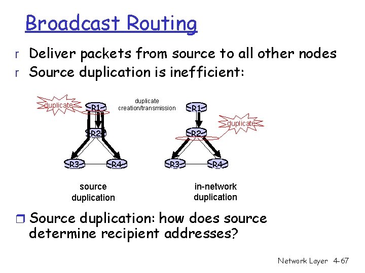
Broadcast Routing r Deliver packets from source to all other nodes r Source duplication is inefficient: duplicate creation/transmission R 1 duplicate R 2 R 3 R 1 R 4 source duplication R 3 R 4 in-network duplication r Source duplication: how does source determine recipient addresses? Network Layer 4 -67
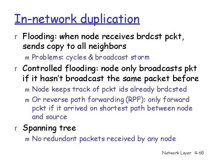
In-network duplication r Flooding: when node receives brdcst pckt, sends copy to all neighbors m Problems: cycles & broadcast storm r Controlled flooding: node only broadcasts pkt if it hasn’t broadcast the same packet before Node keeps track of pckt ids already brdcsted m Or reverse path forwarding (RPF): only forward pckt if it arrived on shortest path between node and source m r Spanning tree m No redundant packets received by any node Network Layer 4 -68
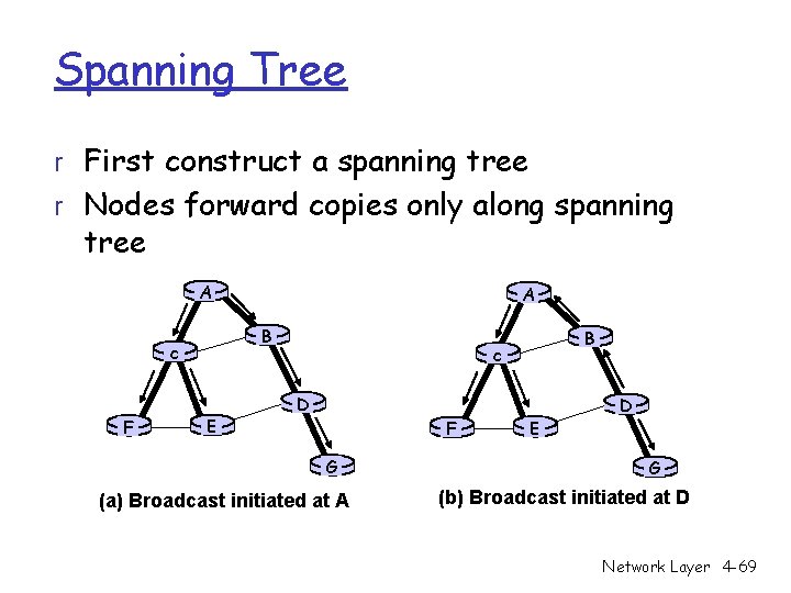
Spanning Tree r First construct a spanning tree r Nodes forward copies only along spanning tree A B c F A E B c D F G (a) Broadcast initiated at A E D G (b) Broadcast initiated at D Network Layer 4 -69
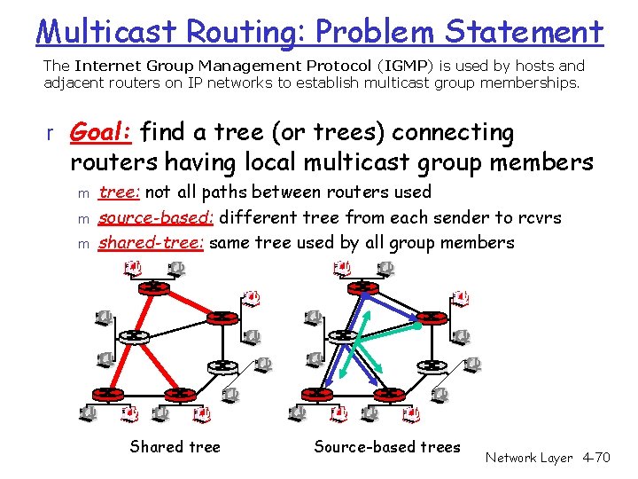
Multicast Routing: Problem Statement The Internet Group Management Protocol (IGMP) is used by hosts and adjacent routers on IP networks to establish multicast group memberships. r Goal: find a tree (or trees) connecting routers having local multicast group members m m m tree: not all paths between routers used source-based: different tree from each sender to rcvrs shared-tree: same tree used by all group members Shared tree Source-based trees Network Layer 4 -70
- Slides: 70