Chapter 4 Modular Combinational Logic Decoders Decoder Realization

Chapter 4 -- Modular Combinational Logic

Decoders

Decoder Realization

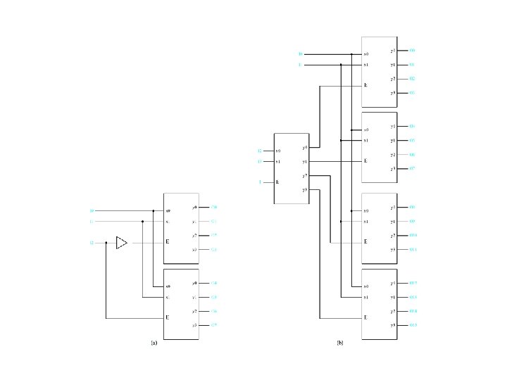
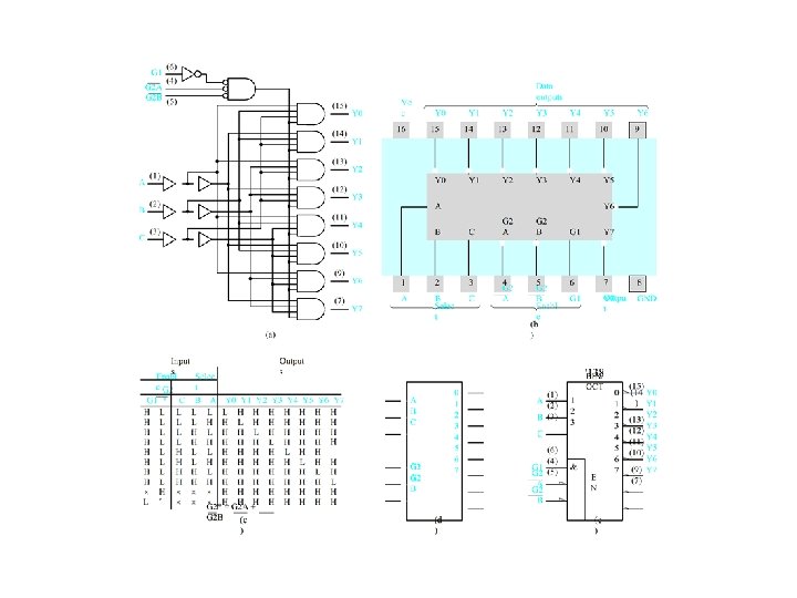
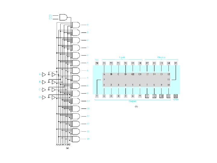
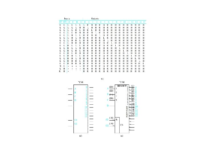
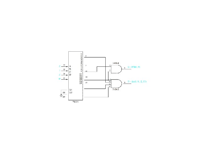
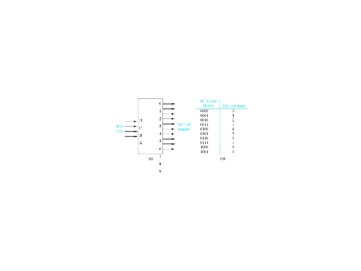
More complex decoders
 = m(0, 1, 4, 6, 7)")
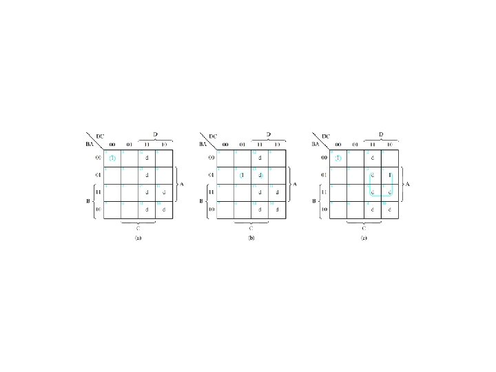
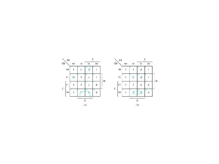
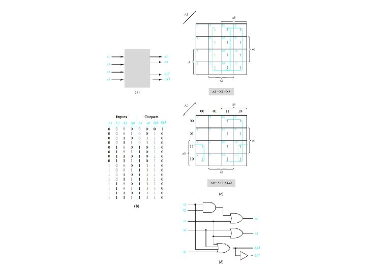
Example 4. 1 -- Realize f(Q, X, P) = m(0, 1, 4, 6, 7) = M(2, 3, 5)
")
Example 4. 1 (concluded)

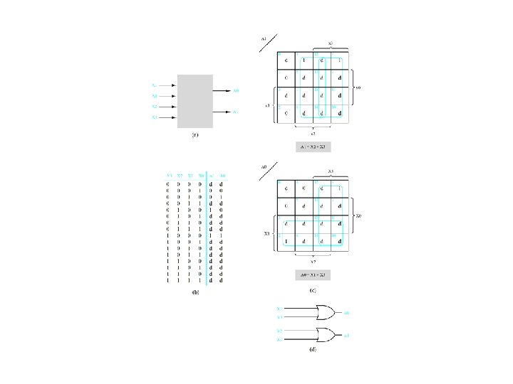
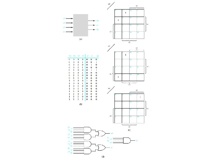
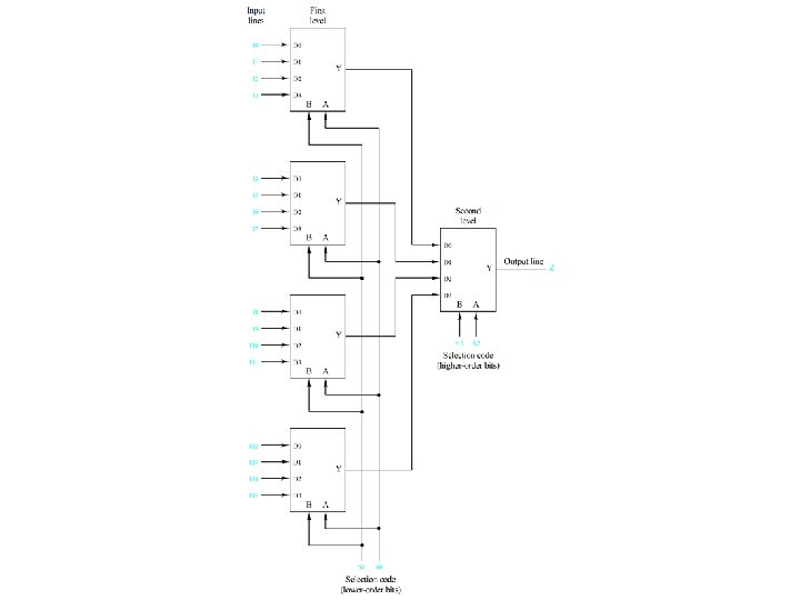
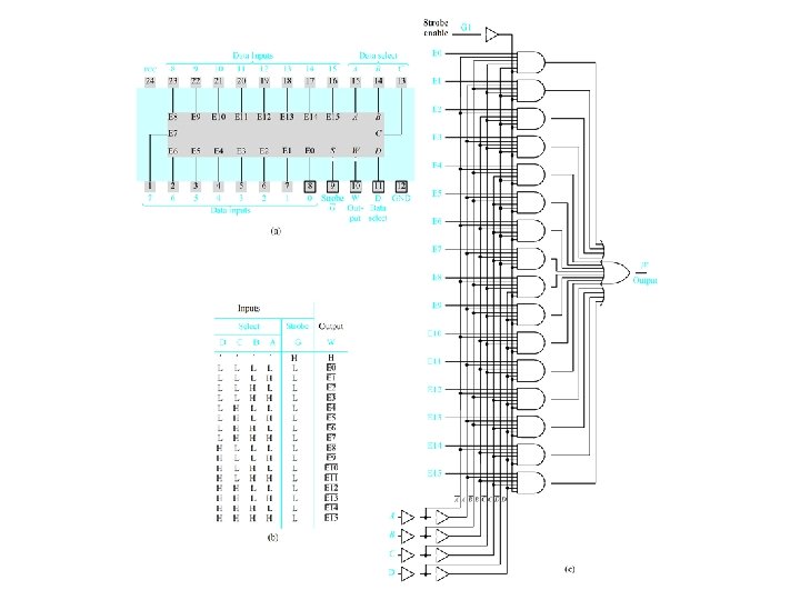
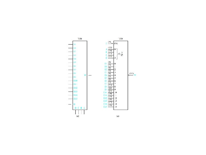
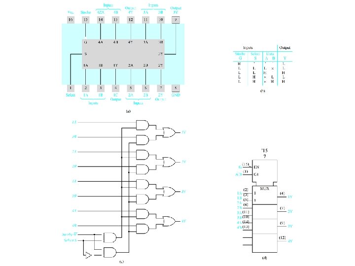
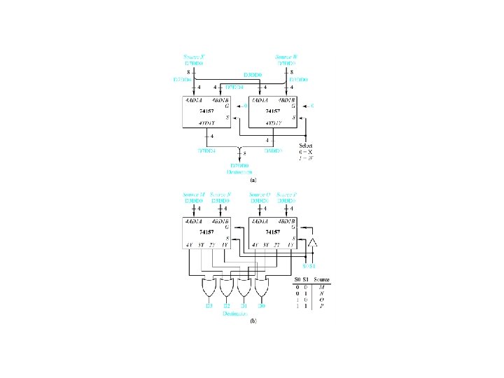
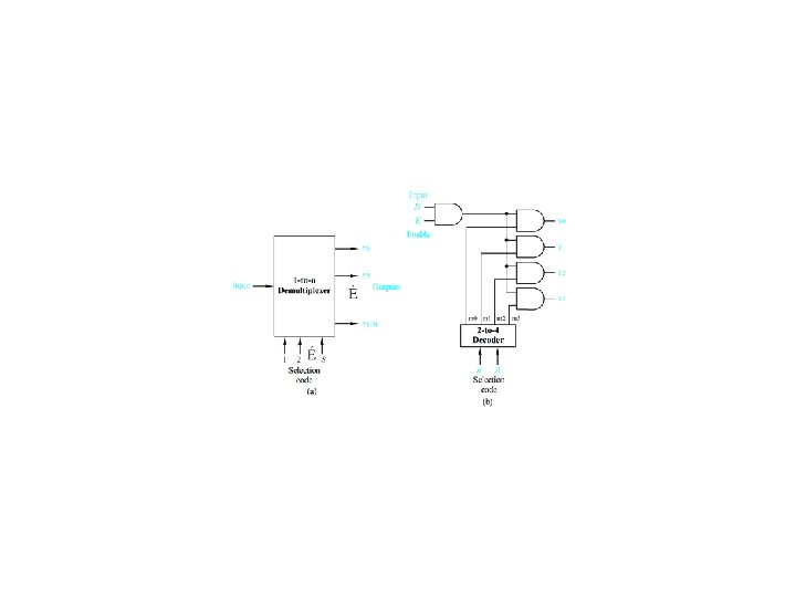
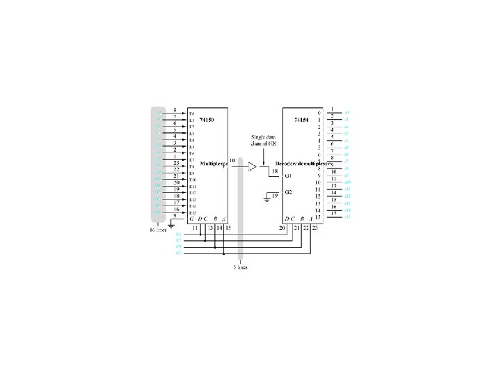
K-Channel multiplexing/demultiplexing Figure 4. 22

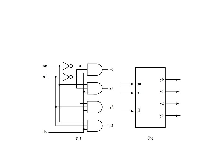
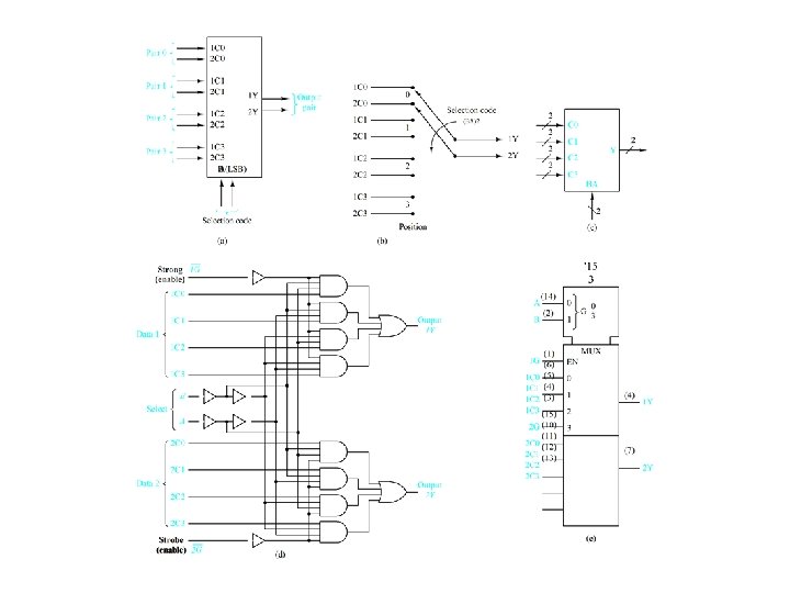
Four-to-one multiplexer design
 =")
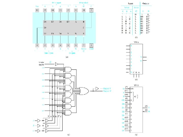
Use a 74151 A multiplexer to Realize f(x 1, x 2, x 3) = m(0, 2, 3, 5) Figure 4. 30
 -- (c)")
Half Adders Figure 4. 35 (a) -- (c)
 -- (g)")
Full Adders Figure 4. 35 (d) -- (g)

Ripple Carry Adder Figure 4. 36

Addition Time for a Basic Ripple-Carry Adder Let tgate = the propogation delay through a typical logic gate Half adder propagation delays tadd = 3 tgate tcarry = 2 tgate Full adder propagation delays tadd = 3 tgate tcarry = 2 tgate Ripple-Carry Adder (n-bits) tadd = (n - 1)2 tgate + 3 tgate = (2 n + 1) tgate

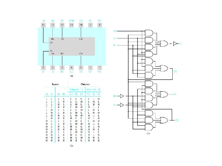
SN 7482 Two-Bit Pseudo Parallel Adder Module Package Pin Configuration

SN 7482 Pseudo Parallel Adder -- Truth Table

SN 7482 Pseudo Parallel Adder -- Logic Diagram

SN 7482 Two-Bit Adder -- Logic Equations C 1 = C 0 A 1 + C 0 B 1 + A 1 B 1 (4. 20) 1 = C 0 C 1 + A 1 C 1 + B 1 C 1 + A 1 B 1 C 0 = C 1 (C 0 + A 1 + B 1) + A 1 B 1 C 0 = (C 0 +A 1 )(C 0 +B 1 )(A 1 +B 1 ) (C 0 +A 1+B 1) +A 1 B 1 C 0 = (C 0 + A 1 B 1 )(A 1 +B 1 )(C 0 +A 1+B 1) +A 1 B 1 C 0 = [C 0 (A 1+B 1)+ C 0 A 1 B 1 ](A 1 +B 1 )+A 1 B 1 C 0 = C 0 A 1 B 1 +C 0 A 1 B 1+C 0 A 1 B 1 +A 1 B 1 C 0 = C 0 A 1 B 1 (4. 21) Similarly C 2 = C 1 A 2 + C 1 B 2 + A 2 B 2 2 = C 1 A 2 B 2 (4. 22)

Add Time for SN 7482 Adder Circuits SN 7482 propagation delays t 1 t. C 1 t 2 t. C 2 = 5 tgate = 2 tgate = 6 tgate = 4 tgate SN 7482 -based ripple-carry adder (n-bits) tadd = (2 n + 2) tgate

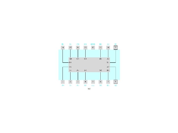
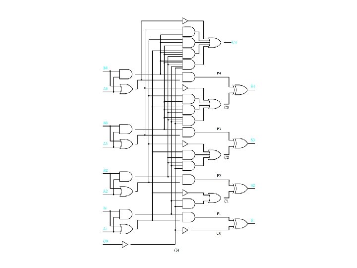
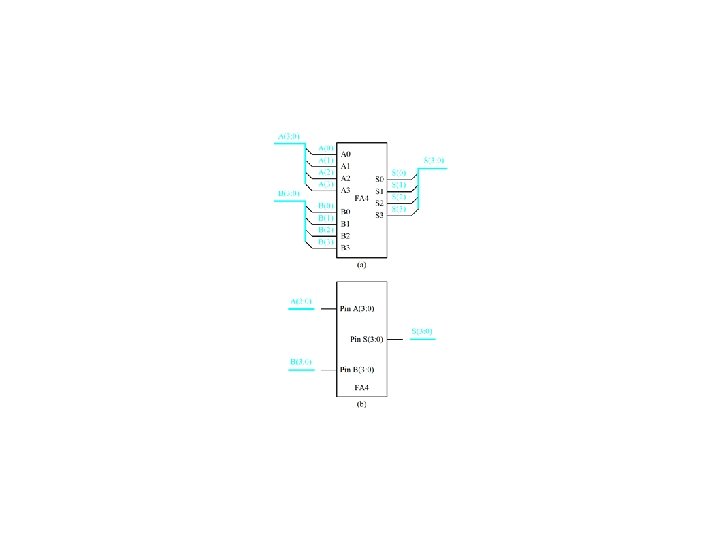
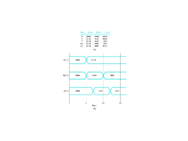
SN 7483 Four-Bit Adder Module Package Pin Configuration

SN 7483 Four-Bit Adder Module -- Logic Diagram
 (Ai + Bi)")
SN 7483 Four-Bit Adder -- Logic Equations Pi = (Bi. Ai) (Ai + Bi) = (Ai + Bi )(Ai + Bi) = Ai Bi (4. 24) i = Pi Ci-1 = Ai Bi Ci-1 (4. 25) C 1 = [C 0 (A 1 B 1) + (A 1 + B 1) ] = [C 0 (A 1 B 1) ] (A 1 + B 1) = (C 0+(A 1 B 1))(A 1 + B 1) = C 0 A 1 + C 0 B 1 + A 1 B 1 (4. 26) Similarly Ci = Ci-1 Ai + Ci-1 Bi + Ai. Bi

Add Times for SN 7483 Adder Circuits SN 7483 propagation delays t 1 = 3 tgate t 2 = t 3 = t 4 = 4 tgate t. C 1 = t. C 2 = t. C 3 = t. C 4 = 3 tgate SN 7483 -based Ripple-Carry Adder (n-bits) tadd = (3 m + 1) tgate where m = n/4.

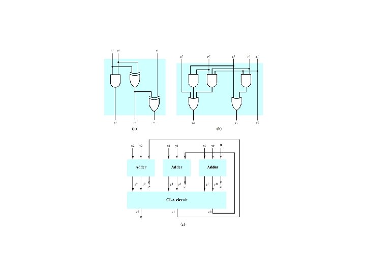
Fully Parallel Three-Bit Adder c 0 = x 0 y 0 s 0 = x 0 y 0 (4. 30) c 1 = x 1 y 1 c 0’+x 1 y 1 c 0+x 1 y 1’c 0+x 1’y 1 c 0 = x 1 y 1+(x 1 y 1)(x 0 y 0) s 1 = x 1 y 1 c 0 = x 1 y 1 x 0 y 0 (4. 31) c 2 = x 2 y 2+(x 2 y 2)c 1 = x 2 y 2+(x 2 y 2)[x 1 y 1+(x 1 y 1)(x 0 y 0)] = x 2 y 2+(x 2 y 2)(x 1 y 1)+(x 2 y 2)(x 1 y 1)(x 0 y 0) s 2 = x 2 y 2 c 1 = x 2 y 2 [x 1 y 1+(x 1 y 1)(x 0 y 0)] (4. 32)

Add Time for a Fully Parallel Adder Assuming a three-level realization tadd = 3 tgate However, the fan in requirements become impractical as n increases.

Carry Look-Ahead Adders -- Basic Idea Recall that ci = xiyi + xici-1 + yici-1 = xiyi + xiyici-1 + xiyici-1 + xi yici-1 = xiyi + xiyi ci-1 + xi yici-1 = xiyi + (xiyi + xi yi)ci-1 = xiyi + (xi yi)ci-1 Let gi = xiyi [carry generate] (4. 33) pi = xi yi [carry propagate] (4. 34) Then ci = gi + pi ci-1 si = pi ci-1 (4. 38)

Carry Look-Ahead Adders -- Three-Bit Example c 0 = g 0 s 0 = p 0 c 1 = g 1 + p 1 c 0 = g 1 + p 1 g 0 s 1 = p 1 c 0 c 2 = g 2 + p 2 c 1 = g 2 + p 2(g 1 + p 1 g 0) = g 2 + p 2 g 1 + p 2 p 1 g 0 s 2 = p 2 c 1 (4. 35) (4. 36) (4. 37)
 Figure 4. 39")
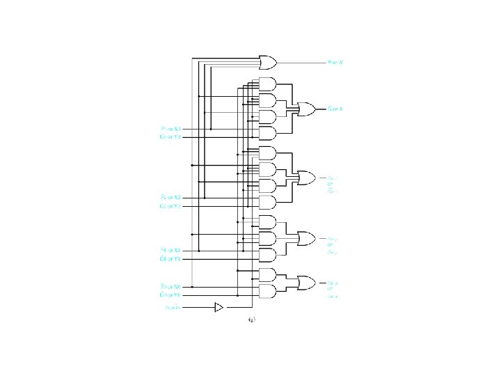
Carry Look-Ahead Adder Design (c) Figure 4. 39

Add Times for Carry Look-Ahead Adders Adder modules tg = tp = ts = tgate CLA module tc = 2 tgate Overall tadd = tgate + 2 tgate + tgate = 4 tgate
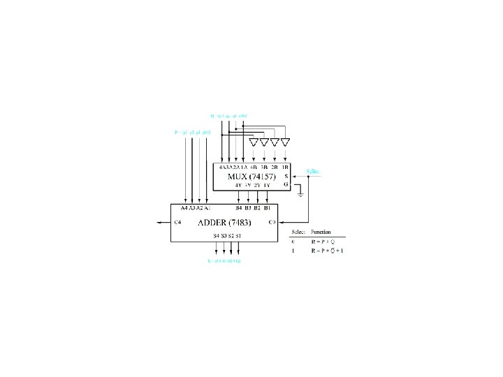
2 = (P)2 - (Q)2 = (P)2 + (-Q)2")
Binary Subtraction Circuits Recall that (R)2 = (P)2 - (Q)2 = (P)2 + (-Q)2 = (P)2 + [Q]2 = (P)2 + (Q)2 + 1 For an SN 7483 adder ( )2 = (A)2 + (B)2 + (C 0)2 where (4. 39) = 4 3 2 1, A = A 4 A 3 A 2 A 1, and B = B 4 B 3 B 2 B 1 If C 0 = 0, A = P, and B = Q, then ( )2 = (P)2 + (Q)2. If C 0 = 1, A = P, and B = Q , then ( )2 = (P)2 - (Q)2.

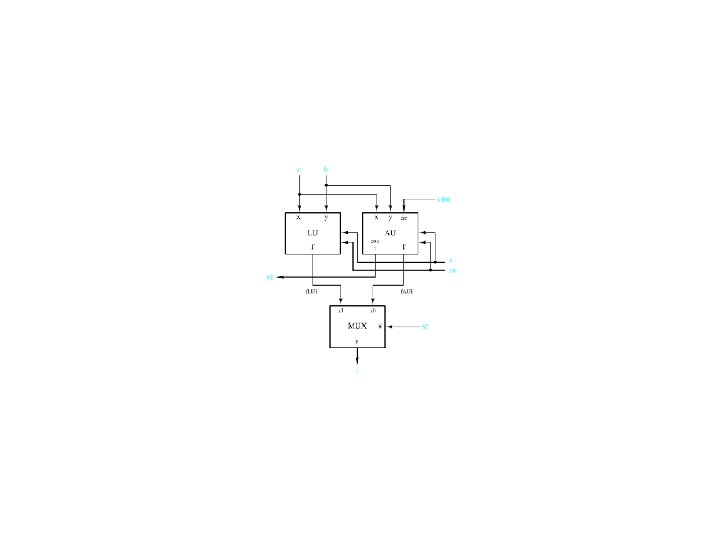
Two’s Complement Adder/Subtracter Figure 4. 41

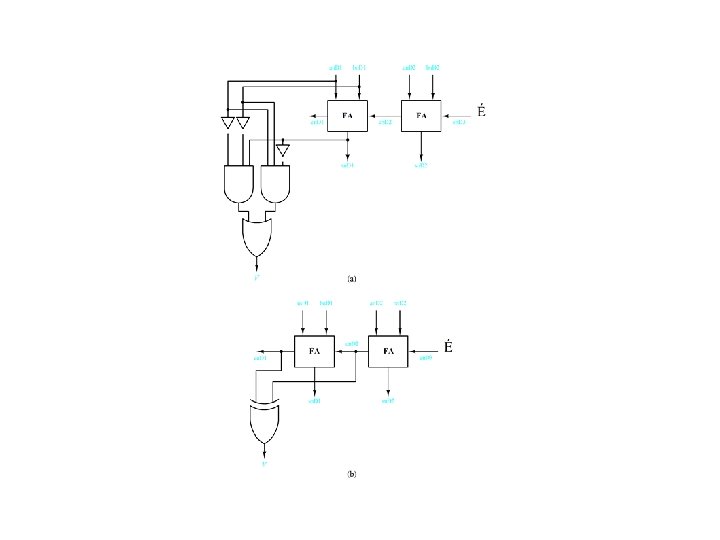
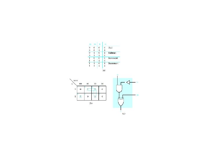
Arithmetic Overflow Detection an-1 bn-1 cn-2 cn-1 sn-1 V 0 0 1 1 0 0 0 1 1 1 0 0 0 0 1 1 0 1 0 1 0 1 0 0 1

Overflow Detection Circuits Figure 4. 42

Decoders

Decoder Realization

More complex decoders
 = m(0, 1, 4, 6, 7)")
Example 4. 1 -- Realize f(Q, X, P) = m(0, 1, 4, 6, 7) = M(2, 3, 5)
")
Example 4. 1 (concluded)

K-Channel multiplexing/demultiplexing Figure 4. 22

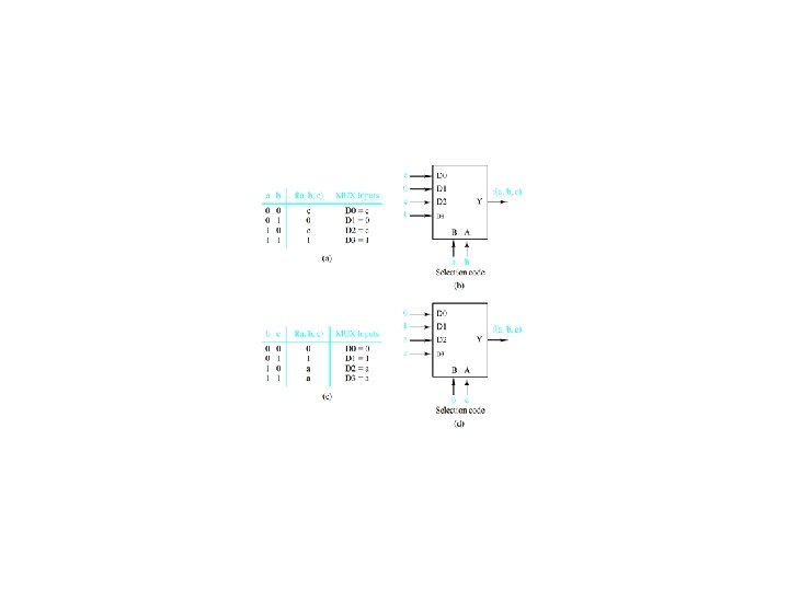
Four-to-one multiplexer design

 =")
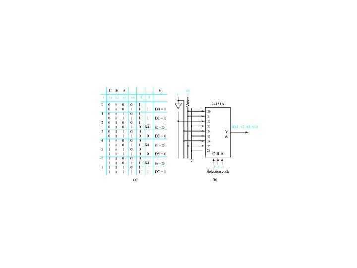
Use a 74151 A multiplexer to Realize f(x 1, x 2, x 3) = m(0, 2, 3, 5) Figure 4. 30
- Slides: 95