CHAPTER 4 LATHE MACHINE 1 1 Introduction 1


 Tools - Used when work must be grooved or parted off.")


- Slides: 39
CHAPTER 4 LATHE MACHINE 1. 1 Introduction 1. 2 Lathe Machines 1. 2. 1 Introduction 1. 2. 2 Part of the Lathe Machines 1. 2. 3 Lathe Accessories 1. 2. 4 Cutting Speed, Feed, and Depth of Cut 1. 2. 5 Lathe Operations
1. 1 Introduction The lathe is a machine tool used principally for shaping pieces of metal (and sometimes wood or other materials) by causing the workpiece to be held and rotated by the lathe while a tool bit is advanced into the work causing the cutting action. • The basic lathe that was designed to cut cylindrical metal stock has been developed further to produce turning, screw threads, tapered work, drilled holes, knurled surfaces, boring and crankshafts. • Modern lathes offer a variety of rotating speeds and a means to manually and automatically move the cutting tool into the workpiece. •
Figure 4. 1: Lathe Size is Indicated by the Swing and the Length of the Bed
1. 2 Lathe Machines 1. 2. 1 Introduction • Lathe machine have three types: ~ lightweight - generally small lathes with a swing of 10 in. or less, mounted to a bench or table top. These lathes can accomplish most machining jobs, but may be limited due to the size of the material that can be turned. ~ toolroom - standard manufacturing lathes and are used for all lathe operations and can be adapted for special milling operations with the appropriate fixture. This type of lathe can handle workpieces up to 25 in. in diameter and up to 200 in. long. However, the general size is about a 15 in. swing with 36 to 48 in. between centers.
~ gap-bed - similar to toolroom lathes except that gap lathes can be adjusted to machine larger diameter and longer workpieces. The operator can increase the swing by moving the bed a distance from the headstock, which is usually one or two feet. By sliding the bed away from the headstock, the gap lathe can be used to turn very long workpieces between centers.
1. 2. 2 Parts of the Lathe Machines Figure 4. 2: The parts of an Lathe Machines
Bed is a heavy, rugged casting made to support the working parts of the lathe. On its top section are machined ways that guide and align the major parts of the lathe. • Headstock is clamped on the left-hand side of the bed. Consist cylindrical shaft supported by bearings, provides a drive through gears from the motor to work-holding devices. • Quick-change Gearbox containing a number of different-size gears, provides the feed rod and lead screw with various speeds for turning and thread-cutting operations when the automatic feed lever is engaged. • Tailstock supports one end of the work when machining between centers, supports long pieces held in the chuck, and holds various forms of cutting tools, such as drills, reamers, and taps. The tailstock can be locked in any position along the bed of the lathe. •
• Carriage consisting of the three main parts: the saddle, cross-slide, and apron. Its used to move the cutting tool along the lathe bed. Figure 4. 3: The Main Parts of Carriage and Tailstock
1. 2. 3 Lathe Accessories • Many lathe accessories are available to increase the versatility of the lathe and the variety of work that can be machined. • Lathe accessories divided into two categories: ~ Work-holding, -supporting, and -driving devices -Lathe centers, chucks, faceplates -Mandrels, steady and follower rests -Lathe dogs, drive plates ~ Cutting-tool-holding devices -Straight and offset toolholders -Threading toolholders, boring bars -Turret-type toolposts
Work-Holding Devices • Lathe Centers - merely support the work while the cutting operations are performed. Most common have solid Morse taper shank 60º centers, steel with carbide tips. • Figure 4. 4: A variety of 60º lathe centers
~ revolving tailstock centers - Used to support work held in chuck or when work is being machined between centers. ~ microset adjustable center - Provides means of aligning lathe centers or producing slight tapers on work machined between centers. ~ self-driving live center - Used when entire length of workpiece is being machined in one operation.
• Chucks - Used extensively for holding work for machining operations. Most commonly used lathe chucks are: ~ three-jaw chuck - Grasps work quickly and accurate within and move simultaneously when adjusted by chuck wrench. Figure 4. 5: A three-jaw and four-jaw chuck
~ four-jaw independent chuck - Used to hold round, square, hexagonal, and irregularly shaped workpieces. Each can be adjusted independently by chuck wrench. ~ collet chuck - Most accurate chuck and used for high-precision work. Spring collets available to hold round, square, or hexagonshaped workpieces. ~ magnetic chucks - Used to hold iron or steel parts that are too thin or may be damaged if held in conventional chuck. Only for light cuts and for special grinding applications. ~ faceplates - Used to hold work too large or shaped so it cannot be held in chuck or between centers. ~ steadyrest - Used to support long work held in chuck or between lathe centers.
• Lathe Dogs - Drives work machined between centers. Tail of dog fits into slot on driveplate and provides drive to workpiece. Figure 4. 6: Common types of lathe dogs
Cutting-Tool-Holding Devices • Toolholders for turning operations are available in three styles: lefthand offset, right-hand offset, straight, and carbide. ~ Left-Hand Offset Toolholder - Designed for machining work close to chuck or faceplate and cutting right to left. • Figure 4. 7: Left-Hand Offset Toolholder
~ Right-Hand Offset Toolholder - Designed for machining work close to the tailstock and cutting left to right. Figure 4. 8: Right-Hand Offset Toolholder ~ Straight Toolholder - Used for taking cuts in either direction and for general machining operations. Figure 4. 9: Straight Toolholder
~ Carbide Toolholder - Has square hole parallel to base of toolholder to accommodate carbide-tipped tool bits and indexable carbide inserts. Figure 4. 10: Carbide-Tipped Toolbits Figure 4. 11: Indexable Carbide Inserts
~ Cutting-Off (Parting) Tools - Used when work must be grooved or parted off. Long, thin cutting-off blade locked securely in toolholder by either cam lock or locking nut. ~ Threading Toolholder - Designed to hold special form-relieved thread-cutting tool. ~ Boring Toolholders - Held in standard toolpost: -Light boring toolholder-Used for small holes and light cuts. -Medium boring toolholder-Suitable for heavier cuts. • Compound Rest Tooling Systems - Fits into T-slot of compound rest. Provides means of holding and adjusting type of toolholder or cutting tool required. Concave ring and the wedge or rocker provide for adjustment of cutting-tool height.
1. 2. 4 Cutting Speed, Feed, and Depth of Cut • The most important factors affecting the efficiency of a lathe operation are cutting speeds and feeds. • Cutting Speed • Lathe work cutting speed defined as the rate at which point on work circumference travels past cutting tool. • Always expressed in feet per minute (ft/min) or meters per minute (m/min). Turning and Boring Rough Cut Finish Cut m/min Threading Material m/min Machine steel 90 100 11 Tool steel 21 27 9 Cast iron 18 24 8 Bronze 90 100 8 Aluminum 61 93 18
• Calculation Cutting Speed ~ To calculate the lathe spindle speed in revolutions per minute (r/min), cutting speed of metal and diameter of work must be known. ~ Formula for r/min of the lathe machine: simplify formula • Example: Calculate the r/min required to turn a 45 mm diameter piece of machine steel (CS 40 m/min).
• • • Feed Rate The feed of a lathe defined as distance cutting tool advances along length of work for every revolution of the spindle. Feed of lathe machine dependent on speed of lead screw for feed rod. Two Cuts Used to Bring Diameter to Size Roughing cut ~ Purpose to remove excess material quickly. ~ Coarse feed: surface finish not too important (0. 25 mm to 0. 4 mm). Finishing cut ~ Used to bring diameter to size. ~ Fine feed: Produce good finish (0. 07 mm to 0. 012 mm).
• • Depth of Cut The depth of cut defined as depth of chip taken by cutting tool and one-half total amount removed from workpiece in one cut. Only one roughing and one finishing cut ~ Roughing cut should be deep as possible to reduce diameter to within 0. 76 mm to 1 mm of size required. ~ Finishing cut should not be less than 0. 0012 mm. Factors Determining Depth of Rough-Turning Cut ~ Condition of machine ~ Type and shape of cutting tool used ~ Rigidity of workpiece, machine, and cutting tool ~ Rate of feed
• Calculate Machining Time ~ Any machinist should be able to estimate the time required to machine a workpiece. ~ Formula; ~ Example: Calculate the time required to machine a 2 in. diameter machine-steel shaft 16 in. long to 1. 850 in diameter finish size. - roughing cut (see table 47. 1, p 369) - roughing feed = 0. 020 (see Table 47. 2, p 370) -
- finishing cut - finishing feed =. 003 - Total Machine Time = Roughing Cut Time + Finishing Cut Time = 4. 4 + 24. 7 = 29. 1 min
1. 2. 5 Lathe Operations • Machining Between Centers, the most common operations as facing, rough and finish, shoulder, filing, and polishing. ~ rough turning - removes as much metal as possible in shortest length of time. Accuracy and surface finish are not important in this operation. ~ finish turning – which follows rough turning, produces a smooth surface finish and cuts the work to an accurate size. ~ filing in a Lathe – remove small amount of stock, remove burrs, or round off sharp corners. Cover lathe bed with paper before filing. ~ polishing in a Lathe – after the work has been filed, the finish may be improved by polishing with abrasive cloth.
Figure 4. 12: Filing in a Lathe ~ turning to a shoulder – when turning more than one diameter on a piece of work, the change in diameters, or step. Figure 4. 13: Types of Shoulder
• Knurling, Grooving, and Form Turning, alter either the shape or the finish of a round workpiece. ~ Knurling - process of impressing a diamond-shaped or straightline pattern into the surface of the workpiece to provide hand grip on the diameter. Figure 4. 14: Knurling Operation
~ Grooving – commonly called recessing, undercutting, or necking, is often done at the end of a thread to permit full travel of nut up to a shoulder or at edge of shoulder for proper fit. Figure 4. 15: Three types of common grooves
~ Form Turning on a Lathe – need irregular shapes or contours from workpiece. Figure 4. 16: Types of Form Turning
• Taper Turning – taper defined as a uniform change in the diameter of a workpiece measure along its axis. Figure 4. 17: Turning A Short Taper Figure 4. 18: Turning A Long Taper
• Thread Cutting - used for holding parts together, making adjustments, and transmitting power and motion. Massed-produced by taps, dies, thread rolling, thread milling, and grinding. Figure 4. 19: Thread Cutting Operation
• Drilling, Boring, Reaming, and Tapping its internal operation can be performed on work held in a chuck. ~ Drilling - drill enters the workpiece axially through the end and cuts a hole with a diameter equal to that of the tool. Figure 4. 20: Drilling with Centre Lathe
~ Boring - A boring tool enters the workpiece axially and cuts along an internal surface to form different features, such as steps, tapers, chamfers, and contours. The boring tool is a single-point cutting tool, which can be set to cut the desired diameter by using an adjustable boring head. Boring is commonly performed after drilling a hole in order to enlarge the diameter or obtain more precise dimensions. Figure 4. 21: Boring Operation on Lathe
~ Reaming - A reamer enters the workpiece axially through the end and enlarges an existing hole to the diameter of the tool. Reaming removes a minimal amount of material and is often performed after drilling to obtain both a more accurate diameter and a smoother internal finish. Figure 4. 21: Reaming Operation
~ Tapping - A tap enters the workpiece axially through the end and cuts internal threads into an existing hole. The existing hole is typically drilled by the required tap drill size that will accommodate the desired tap. Figure 4. 22: Tapping Operation
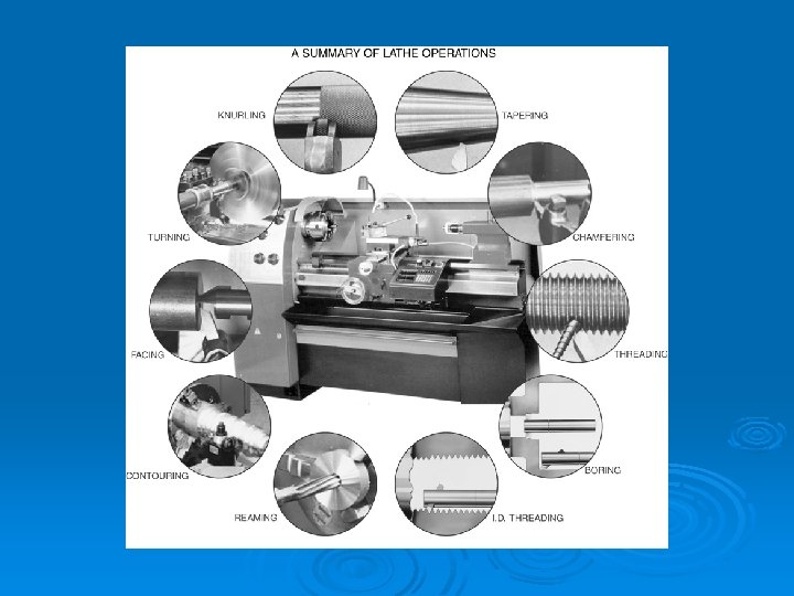
Figure 4. 23: Above are illustrated some of the many types of machining that can be accomplished on a lathe
Headstock Tailstock Bed Quick Change Gearbox Carriage