
Chapter 4 Addressing modes CEG 2400 Microcomputer Systems



![Use of pre-indexed addressing mode LDR r 0, [r 1, #offset] Base plus offset](https://slidetodoc.com/presentation_image_h2/4d2fef79a99005604a6dc01eb1be55ac/image-16.jpg "Use of pre-indexed addressing mode LDR r 0, [r 1, #offset] Base plus offset")
![Pre-indexed addressing, LDR r 0, [r 1, #offset] • Copy and copy 2 (shown](https://slidetodoc.com/presentation_image_h2/4d2fef79a99005604a6dc01eb1be55ac/image-17.jpg "Pre-indexed addressing, LDR r 0, [r 1, #offset] • Copy and copy 2 (shown")
![Pre-indexed with auto addressing mode LDR r 0, [r 1, #offset]! • pre-indexed auto](https://slidetodoc.com/presentation_image_h2/4d2fef79a99005604a6dc01eb1be55ac/image-18.jpg "Pre-indexed with auto addressing mode LDR r 0, [r 1, #offset]! • pre-indexed auto")
![Exercise 4. 3 LDR r 0, [r 1, #4] ; r 0 : =](https://slidetodoc.com/presentation_image_h2/4d2fef79a99005604a6dc01eb1be55ac/image-19.jpg "Exercise 4. 3 LDR r 0, [r 1, #4] ; r 0 : =")
![Exercise 4. 4 LDR r 0, [r 1, #4] ; r 0 : =](https://slidetodoc.com/presentation_image_h2/4d2fef79a99005604a6dc01eb1be55ac/image-20.jpg "Exercise 4. 4 LDR r 0, [r 1, #4] ; r 0 : =")





- Slides: 31
Chapter 4 Addressing modes CEG 2400 Microcomputer Systems CEG 2400 ch 4 addressing modes v 7 a 1
Objective • In this lecture, you will learn some assembly operations for data transfer from CPU to memory / from memory to CPU CEG 2400 ch 4 addressing modes v 7 a 2
Overview 1. Memory concept revision 2. Data Transfer Instructions - LDR instruction (Load Address into Register) Ref: http: //infocenter. arm. com/help/index. jsp? topic=/co m. arm. doc. dui 0041 c/Babbfdih. html 3. Register-indirect addressing using load (LDR) / store (STR) 4. Block copying CEG 2400 ch 4 addressing modes v 7 a 3
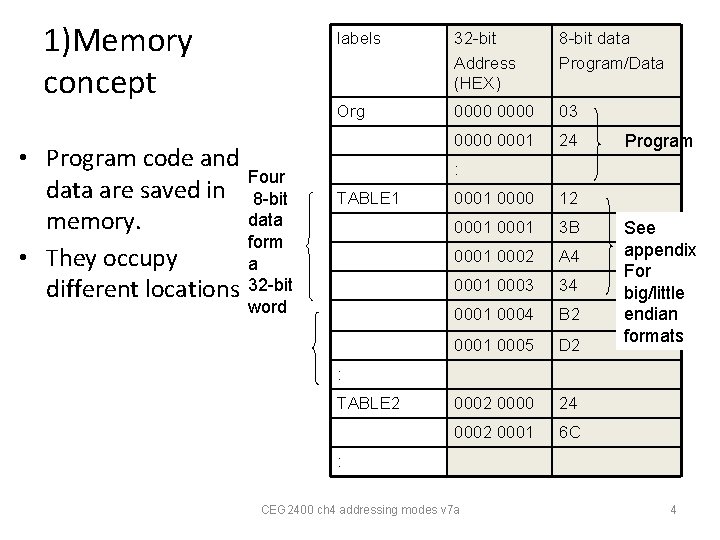
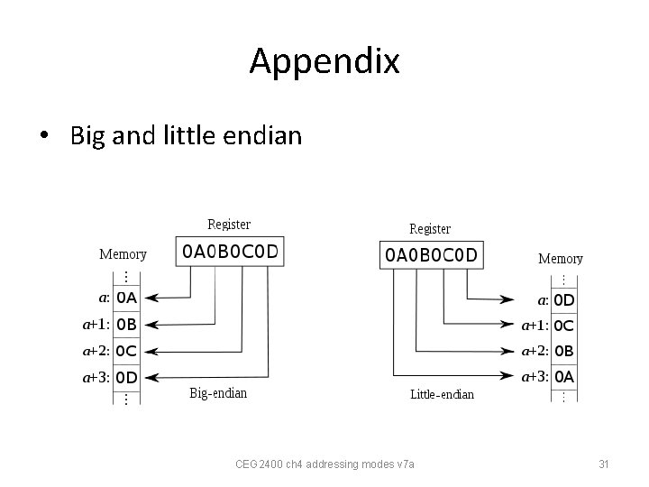
1)Memory concept • Program code and Four data are saved in 8 -bit data memory. form • They occupy a different locations 32 -bit labels 32 -bit Address (HEX) 8 -bit data Program/Data Org 0000 03 0000 0001 24 Program : TABLE 1 word 0001 0000 12 0001 3 B 0001 0002 A 4 0001 0003 34 0001 0004 B 2 0001 0005 D 2 0000 24 0002 0001 6 C See appendix For big/little endian formats : TABLE 2 : CEG 2400 ch 4 addressing modes v 7 a 4
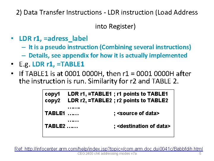
2) Data Transfer Instructions - LDR instruction (Load Address into Register) • LDR r 1, =adress_label – It is a pseudo instruction (Combining several instructions) – Details, see appendix for how it is actually implemented • E. g. LDR r 1, =TABLE 1 • If TABLE 1 is at 0001 0000 H, then r 1 = 0001 0000 H after the instruction is run. Similarity for r 2 and TABLE 2. copy 1 copy 2 LDR r 1, =TABLE 1 ; r 1 points to TABLE 1 LDR r 2, =TABLE 2 ; r 2 points to TABLE 2 ……. TABLE 1 …… ; <source of data> …… TABLE 2 …… ; <destination of data> Ref: http: //infocenter. arm. com/help/index. jsp? topic=/com. arm. doc. dui 0041 c/Babbfdih. html CEG 2400 ch 4 addressing modes v 7 a 5
3) Register-indirect addressing using load (LDR) / store (STR) http: //infocenter. arm. com/help/index. jsp? topic=/com. arm. doc. dui 0041 c/Babbfdih. html CEG 2400 ch 4 addressing modes v 7 a 6
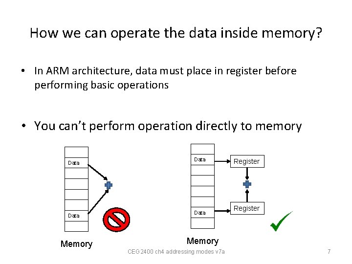
How we can operate the data inside memory? • In ARM architecture, data must place in register before performing basic operations • You can’t perform operation directly to memory Data Memory Data Register Memory CEG 2400 ch 4 addressing modes v 7 a 7
Reason to use Load (LDR) / store (STR) • Therefore, we need the operation to help us load the data from memory to register, and store the data from register to memory. CEG 2400 ch 4 addressing modes v 7 a 8
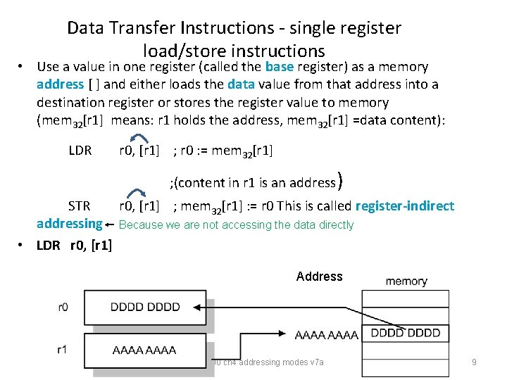
Data Transfer Instructions - single register load/store instructions • Use a value in one register (called the base register) as a memory address [ ] and either loads the data value from that address into a destination register or stores the register value to memory (mem 32[r 1] means: r 1 holds the address, mem 32[r 1] =data content): LDR r 0, [r 1] ; r 0 : = mem 32[r 1] ; (content in r 1 is an address) STR r 0, [r 1] ; mem 32[r 1] : = r 0 This is called register-indirect addressing Because we are not accessing the data directly • LDR r 0, [r 1] Address CEG 2400 ch 4 addressing modes v 7 a 9
Example : Data Transfer Instructions • Use LDR copy TABLE 1 TABLE 2 LDR LDR STR ……. …… …… …… r 1, =TABLE 1 r 2, =TABLE 2 r 0, [r 1] r 0, [r 2] ; r 1 points to TABLE 1 ; r 2 points to TABLE 2 ; load first value …. ; and store it in TABLE 2 ; <source of data> ; <destination of data> CEG 2400 ch 4 addressing modes v 7 a 10
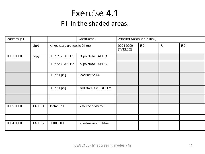
Exercise 4. 1 Fill in the shaded areas. Address (H) • 0001 0000 0002 0000 Comments start All registers are rest to 0 here copy LDR r 1, =TABLE 1 ; r 1 points to TABLE 1 LDR r 2, =TABLE 2 ; r 2 points to TABLE 2 LDR r 0, [r 1] ; load first value STR r 0, [r 2] ; and store it in TABLE 2 : : 12345678 ; <source of data> TABLE 1 After instruction is run (hex) 0004 0000 (TABLE 2) R 0 R 1 R 2 : 0004 0000 TABLE 2 00000063 ; <destination of data> CEG 2400 ch 4 addressing modes v 7 a 11
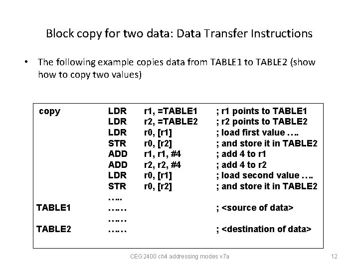
Block copy for two data: Data Transfer Instructions • The following example copies data from TABLE 1 to TABLE 2 (show to copy two values) copy TABLE 1 TABLE 2 LDR LDR STR ADD LDR STR …. . …… …… …… r 1, =TABLE 1 r 2, =TABLE 2 r 0, [r 1] r 0, [r 2] r 1, #4 r 2, #4 r 0, [r 1] r 0, [r 2] ; r 1 points to TABLE 1 ; r 2 points to TABLE 2 ; load first value …. ; and store it in TABLE 2 ; add 4 to r 1 ; add 4 to r 2 ; load second value …. ; and store it in TABLE 2 ; <source of data> ; <destination of data> CEG 2400 ch 4 addressing modes v 7 a 12
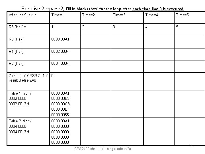
Exercise 2 --page 1 Block copy for N=5 data : Data Transfer Instructions • Copy N=5 data from TABLE 1 to TABLE 2 1. copy 2. 3. 4. loop 1 5. 6. 7. 8. 9. 10. TABLE 1 TABLE 2 LDR MOV LDR STR ADD ADD CMP BNE …. . …… …… …… r 1, =TABLE 1 r 2, =TABLE 2 r 3, #0 r 0, [r 1] r 0, [r 2] r 1, #4 r 2, #4 r 3, #1 r 3, #5 loop 1 ; TABLE 1=0002 0000 H ; TABLE 2=0004 0000 H ; setup counter at R 3 ; load first value …. ; and store it in TABLE 2 ; add 4 to r 1 ; add 4 to r 2 ; increment counter ; repeat N=5 ; loop back when N<5 ; <source of data> ; <destination of data> CEG 2400 ch 4 addressing modes v 7 a 13
Exercise 2 --page 2, Fill in blacks (hex) for the loop after each time line 9 is executed After line 9 is run Time=1 Time=2 Time=3 Time=4 Time=5 R 3 (Hex)= 1 2 3 4 5 R 0 (Hex) 0000 00 A 1 R 1 (Hex) 0002 0004 R 2 (Hex) 0004 Z (zero) of CPSR, Z=1 if result 0 else Z=0 0 Table 1, from 0002 00000002 0013 H 0000 00 A 1 0000 00 B 2 0000 00 C 3 0000 00 D 4 0000 0055 Table 2, from 0004 00000004 0013 H 0000 00 A 1 0000 0000 CEG 2400 ch 4 addressing modes v 7 a 14
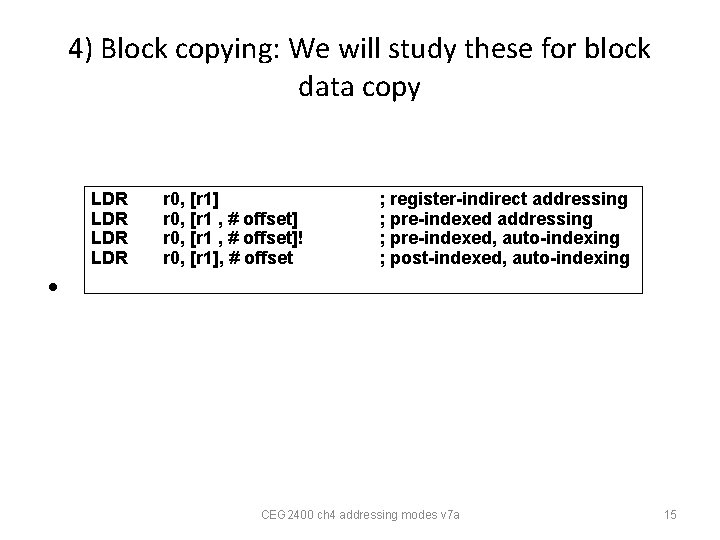
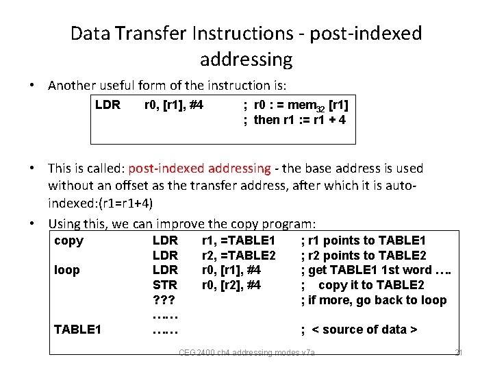
4) Block copying: We will study these for block data copy LDR LDR r 0, [r 1] r 0, [r 1 , # offset]! r 0, [r 1], # offset ; register-indirect addressing ; pre-indexed, auto-indexing ; post-indexed, auto-indexing • CEG 2400 ch 4 addressing modes v 7 a 15
Use of pre-indexed addressing mode LDR r 0, [r 1, #offset] Base plus offset addressing • pre-indexed addressing mode LDR r 0, [r 1, #4] base address • ; r 0 : = mem 32 [r 1 + 4] offset effective address r 1 Unchanged LDR r 0, [r 1, #4] ; r 0 : = mem 32 [r 1 + 4] r 1 will not be changed by pre-indexed addressing instructions CEG 2400 ch 4 addressing modes v 7 a 16
Pre-indexed addressing, LDR r 0, [r 1, #offset] • Copy and copy 2 (shown below) have the same effect copy Simple method copy 2 Better method using pre-indexing LDR LDR STR ADD LDR STR LDR LDR STR r 1, =TABLE 1 r 2, =TABLE 2 r 0, [r 1] r 0, [r 2] r 1, #4 r 2, #4 r 0, [r 1] r 0, [r 2] ; r 1 points to TABLE 1 ; r 2 points to TABLE 2 ; load first value …. ; and store it in TABLE 2 ; step r 1 onto next word ; step r 2 onto next word ; load second value … ; and store it r 1, =TABLE 1 r 2, =TABLE 2 r 0, [r 1] r 0, [r 2] r 0, [r 1, #4] r 0, [r 2, #4] ; r 1 points to TABLE 1 ; r 2 points to TABLE 2 ; load first value …. ; and store it in TABLE 2 ; load second value … ; and store it CEG 2400 ch 4 addressing modes v 7 a 17
Pre-indexed with auto addressing mode LDR r 0, [r 1, #offset]! • pre-indexed auto addressing mode, using (!), changes the pointer reg. (e. g. r 1 here ) after used. • LDR r 0, [r 1, #4]! base address ; r 0 : = mem 32 [r 1 + 4] offset effective address • r 1 = r 1+offset=r 1+#4 LDR r 0, [r 1, #4]! ; r 0 : = mem 32 [r 1 + 4] ; r 1 : = r 1 + 4 r 1 will be changed by pre-indexed addressing instructions CEG 2400 ch 4 addressing modes v 7 a 18
Exercise 4. 3 LDR r 0, [r 1, #4] ; r 0 : = mem 32 [r 1 + 4] 1. Copy LDR 2. LDR 3. LDR 4. STR 5. LDR 6. STR • LDR r 0, [r 1, #4]! r 1, =TABLE 1 r 2, =TABLE 2 r 0, [r 1] r 0, [r 2] r 0, [r 1, #4] r 0, [r 2, #4] ; r 0 : = mem 32 [r 1 + 4] ; r 1 : = r 1 + 4 ; TABLE 1=0002 0000 ; TABLE 2=0004 0000 ; load first value …. ; and store it in. TABLE 2 ; load second value ; and store it (all in hex) After Line r 0 r 1 r 2 00000002 0003 0002 00040002 0007 0004 0000 4003 00040004 0007 1 0000 0002 0000 1357 2468 A 123 B 246 0 0 2 3 4 5 6 CEG 2400 ch 4 addressing modes v 7 a r 1, r 2 will NOT be changed by pre-indexed addressing instructions 19
Exercise 4. 4 LDR r 0, [r 1, #4] ; r 0 : = mem 32 [r 1 + 4] • 1. Copy LDR 2. LDR 3. LDR 4. STR 5. LDR 6. STR r 1, =TABLE 1 r 2, =TABLE 2 r 0, [r 1] r 0, [r 2] r 0, [r 1, #4]! r 0, [r 2, #4]! LDR r 0, [r 1, #4]! ; r 0 : = mem 32 [r 1 + 4] ; r 1 : = r 1 + 4 ; TABLE 1=0002 0000 ; TABLE 2=0004 0000 ; load first value …. ; and store it in. TABLE 2 ; load second value, r 1 will change ; and store it, r 2 will change too (all in hex) After line r 0 r 1 r 2 00000002 0003 0002 00040002 0007 0004 00000004 0003 00040004 0007 1 0000 0002 0000 1357 2468 A 123 B 246 0 0 2 3 4 5 6 CEG 2400 ch 4 addressing modes v 7 a r 1, r 2 will be changed by pre-indexed addressing instructions 20
Data Transfer Instructions - post-indexed addressing • Another useful form of the instruction is: LDR r 0, [r 1], #4 ; r 0 : = mem 32 [r 1] ; then r 1 : = r 1 + 4 • This is called: post-indexed addressing - the base address is used without an offset as the transfer address, after which it is autoindexed: (r 1=r 1+4) • Using this, we can improve the copy program: copy loop TABLE 1 LDR LDR STR ? ? ? …… …… r 1, =TABLE 1 r 2, =TABLE 2 r 0, [r 1], #4 r 0, [r 2], #4 ; r 1 points to TABLE 1 ; r 2 points to TABLE 2 ; get TABLE 1 1 st word …. ; copy it to TABLE 2 ; if more, go back to loop ; < source of data > CEG 2400 ch 4 addressing modes v 7 a 21
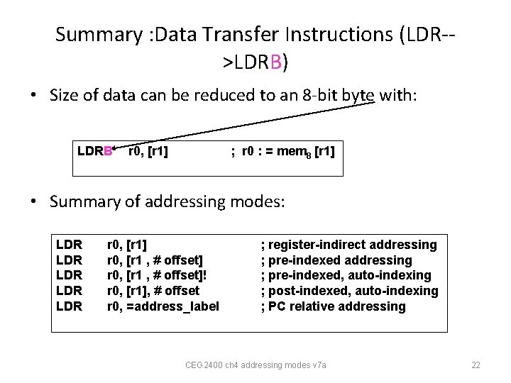
Summary : Data Transfer Instructions (LDR->LDRB) • Size of data can be reduced to an 8 -bit byte with: LDRB r 0, [r 1] ; r 0 : = mem 8 [r 1] • Summary of addressing modes: LDR LDR LDR r 0, [r 1] r 0, [r 1 , # offset]! r 0, [r 1], # offset r 0, =address_label ; register-indirect addressing ; pre-indexed, auto-indexing ; post-indexed, auto-indexing ; PC relative addressing CEG 2400 ch 4 addressing modes v 7 a 22
Self study programming exercise: ; ex 4_2400 ch 4 of CENG 2400. It is for your own revision purpose, no need to submit answers to tutors. • ; http: //www. cse. cuhk. edu. hk/%7 Ekhwong/www 2/c eng 2400/ex 4_2400_qst. txt; 1) create a project based on this. s code ; 2) In keil-ide, use project/rebuild all target files to build the project ; 3) use Debug/run_to_cursor_line to run the top line of the program, ; 4) use the single step mode to view the memory locations (in DEbug mode/view/memory_wndows)from 0 x 4000000 to 0 x 40000013, registers and cpsr after the execution of each statement. ; 5) Explain the observations and results. • • ; declare variables AREA • • Table 1 DCD 0 x 1, 0 x 1, 0 x 1 , 0 x 1 Table 2 DCD 0 x 1, 0 x 1, 0 x 1 , 0 x 1 • • align ; ------------------------------- • • • New test 12 D |. data|, DATA, READWRITE • • • • • • • ; User Initial Stack & Heap AREA |. text|, CODE, READONLY EXPORT __main ; clear flags memory_init ; set the memory content in table 1 LDR r 1, =Table 1 LDR r 2, =Table 2 MOV r 3, #0 MOV r 0, #0 x 00 loop ADD r 0, #0 x 11 STR r 0, [r 1] ADD r 1, #4 ADD r 3, #1 CMP r 3, #10 BNE loop NOP ex 4_1 ; ; ; ; ; ; ; ; ; BL memory_reset LDR r 1, =Table 1 LDR r 2, =Table 2 LDR r 0, [r 1] STR r 0, [r 2] NOP CEG 2400 ch 4 addressing modes v 7 a 23
Self study exercises (continue) • ex 4_2; ; ; ; ; ; ; ; ; • BL memory_reset • LDR r 1, =Table 1 • LDR r 2, =Table 2 • MOV r 3, #0 • loop 1 LDR r 0, [r 1] • STR r 0, [r 2] • ADD r 1, #4 • ADD r 2, #4 • ADD r 3, #1 • CMP r 3, #5 • BNE loop 1 • NOP • • • ex 4_3; ; ; ; BL memory_reset LDR r 1, =Table 1 LDR r 2, =Table 2 LDR r 0, [r 1] STR r 0, [r 2] LDR r 0, [r 1, #4] STR r 0, [r 2, #4] NOP • NOP • ex 4_4; ; ; ; • BL memory_reset • LDR r 1, =Table 1 • LDR r 2, =Table 2 • LDR r 0, [r 1] • STR r 0, [r 2] • LDR r 0, [r 1, #4]! • STR r 0, [r 2, #4]! • NOP • memory_reset ; reset the content in • ; table 2 to be all 0 • LDR r 5, =Table 2 • MOV r 6, #0 • MOV r 7, #0 • loop 2 STR r 6, [r 5] • ADD r 5, #4 • ADD r 7, #1 • CMP r 7, #10 • BNE loop 2 • BX LR CEG 2400 ch 4 addressing modes v 7 a • END 24
Summary • Learned the addressing modes of the Arm processor CEG 2400 ch 4 addressing modes v 7 a 25
Appendices CEG 2400 ch 4 addressing modes v 7 a 26
Appendix 1: MOV • • MOV : Move MOV<suffix> <dest>, <op 1> dest = op_1 • • • MOV loads a value into the destination register, from another register, a shifted register, or an immediate value. You can specify the same register for the effect of a NOP instruction, or you can shift the same register if you choose: • MOV R 0, LSL#3 • ; R 0 = R 0. . . NOP instruction ; R 0 = R 0 * 8 If R 15 is the destination, the program counter or flags can be modified. This is used to return to calling code, by moving the contents of the link register into R 15: • MOV PC, R 14 • • MOVS PC, R 14 ; Exit to caller preserving flags (not 32 -bit compliant) • CEG 2400 ch 4 addressing modes v 7 a 27
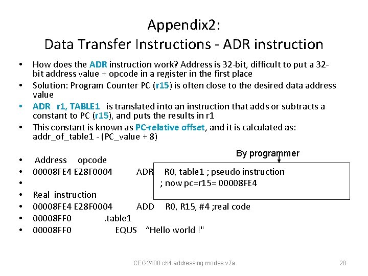
Appendix 2: Data Transfer Instructions - ADR instruction • • • How does the ADR instruction work? Address is 32 -bit, difficult to put a 32 bit address value + opcode in a register in the first place Solution: Program Counter PC (r 15) is often close to the desired data address value ADR r 1, TABLE 1 is translated into an instruction that adds or subtracts a constant to PC (r 15), and puts the results in r 1 This constant is known as PC-relative offset, and it is calculated as: addr_of_table 1 - (PC_value + 8) Address opcode 00008 FE 4 E 28 F 0004 By programmer ADR R 0, table 1 ; pseudo instruction ; now pc=r 15= 00008 FE 4 Real instruction 00008 FE 4 E 28 F 0004 ADD R 0, R 15, #4 ; real code 00008 FF 0. table 1 00008 FF 0 EQUS “Hello world !" CEG 2400 ch 4 addressing modes v 7 a 28
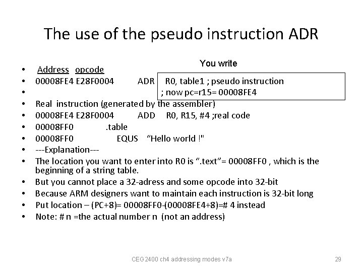
The use of the pseudo instruction ADR • • • • Address opcode 00008 FE 4 E 28 F 0004 You write ADR R 0, table 1 ; pseudo instruction ; now pc=r 15= 00008 FE 4 Real instruction (generated by the assembler) 00008 FE 4 E 28 F 0004 ADD R 0, R 15, #4 ; real code 00008 FF 0. table 00008 FF 0 EQUS “Hello world !" ---Explanation--The location you want to enter into R 0 is “. text”= 00008 FF 0 , which is the beginning of a string table. But you cannot place a 32 -adress and some opcode into 32 -bit Because ARM designers want to maintain each instruction is 32 -bit long Put location – (PC+8)= 00008 FF 0 -(00008 FE 4+8)=# 4 instead Note: # n =the actual number n (not an address) CEG 2400 ch 4 addressing modes v 7 a 29
End CEG 2400 ch 4 addressing modes v 7 a 30
Appendix • Big and little endian CEG 2400 ch 4 addressing modes v 7 a 31