Chapter 4 4 1 Digital Modulation 4 2


 B = bandwidth (Hz) t =")
 B = bandwidth (Hz) = signal")


 Amplitude-shift keying (ASK) is a process where a binary information")

 Called as Binary Frequency Shift Keying (BFSK) The phase shift")
 Similar to the standard frequency modulation (FM) except the modulating")
 As the binary input signal changes from a logic 0")
 Advantages of FSK over ASK : 1. ASK needs automatic")
 PSK is an M-ary digital modulation scheme similar to conventional")
 (a) Figure 4. 9: BPSK in the time domain: (a) waveform, (b) truth")
 Truth Table b) Phasor Diagram c) Constellation Diagram")


 Quadrature-amplitude modulation (QAM) is a form of digital modulation similar to")
 (b) Figure 4. 17: (a) 8 -QAM modulator: output phase-versus-time relationship. (b) Truth")

- Slides: 35
Chapter 4 4. 1 : Digital Modulation 4. 2 : Digital Transmission 4. 3 : Multiple Access Methods
4. 1 Digital Modulation Outlines a. b. c. Introduction Information capacity, Bits, Bit Rate, Baud, M-ary Encoding Digital Modulation Techniques - ASK, FSK, PSK, QAM
INTRODUCTION TO DIGITAL MODULATION Digital modulation : the transmittal of digitally modulated analog signals between two or more points in a communications system. • Can be propagated through Earth’s atmosphere and used in wireless communication system digital radio. • Offer several outstanding advantages over traditional analog system. • Ease of processing • Ease of multiplexing • Noise immunity •
INTRODUCTION TO DIGITAL MODULATION Applications: Low speed voice band data comm. Modems ü High speed data transmission systems ü Digital microwave & satellite comm. Systems ü PCS (personal communication systems) telephone ü
Why digital modulation? The modulation of digital signals with analogue carriers allows an improvement in signal to noise ratio as compared to analogue modulating schemes.
Forms of Digital Modulation ASK FSK PSK QAM • If the amplitude, V of the carrier is varied proportional to the information signal, a digital modulated signal is called Amplitude Shift Keying (ASK) • If the frequency, f of the carrier is varied proportional to the information signal, a digital modulated signal is called Frequency Shift Keying (FSK) • If the phase, θ of the carrier is varied proportional to the information signal, a digital modulated signal is called Phase Shift Keying (PSK)
Cont’d… If both the amplitude and the phase, θ of the carrier are varied proportional to the information signal, a digital modulated signal is called Quadrature Amplitude Modulation (QAM)
Cont’d. . .
Block Diagram Simplified block diagram of a digital modulation system
Cont’d… Precoder performs level conversion & encodes incoming data into group of bits that modulate an analog carrier. Modulated carrier filtered, amplified & transmitted through transmission medium to Rx. In Rx, the incoming signals filtered, amplified & applied to the demodulator and decoder circuits which extracts the original source information from modulated carrier.
Information Capacity, Bits, Bit Rate, Baud, M-ary Encoding Information capacity, Bits & Bit Rate ◦ Information capacity is a measure of how much information can be propagated through a communication system and is a function of bandwidth and transmission time. ◦ represents the number of independent symbols that can be carried through a system in a given unit of time. ◦ Basic digital symbol is the binary digit or bit. ◦ Express the information capacity as a bit rate.
Hartley’s Law Where I = information capacity (bps) B = bandwidth (Hz) t = transmission time (s) From the equation, Information capacity is a linear function of bandwidth and transmission time and directly proportional to both.
Shannon’s Formula Where I = information capacity (bps) B = bandwidth (Hz) = signal to noise power ratio (unitless) The higher S/N the better the performance and the higher the information capacity
Example 2 By using the Shannon’s Formula, calculate the information capacity if S/N = 30 d. B and B = 2. 7 k. Hz.
M-ary Encoding It is often advantageous to encode at a level higher than binary where there are more then two conditions possible. The number of bits necessary to produce a given number of conditions is expressed mathematically as Where N = number of bits necessary M = number of conditions, level or combinations possible with N bits.
Cont’d… Each symbol represents n bits, and has M signal states, where M = 2 N. Find the number of voltage levels which can represent an analog signal with a. 8 bits per sample b. 12 bits per sample
Baud & Minimum BW Baud refers to the rate of change of a signal on the transmission medium after encoding and modulation have occurred. Where baud = symbol rate (symbol per second) ts = time of one signaling element @ symbol (seconds)
Cont’d… Minimum Bandwidth ◦ Using multilevel signaling, the Nyquist formulation for channel capacity Where fb= channel capacity (bps) B = minimum Nyquist bandwidth (Hz) M = number of discrete signal or voltage levels
Cont’d… For B necessary to pass M-ary digitally modulated carriers Where N is the number of bits encoded into each signaling element.
Amplitude Shift Keying (ASK) Amplitude-shift keying (ASK) is a process where a binary information signal directly modulates the amplitude of an analog carrier. ASK is similar to standard amplitude modulation except there are only two output amplitudes possible. Amplitude shift keying is sometimes called digital amplitude modulation (DAM) or on-off keying (OOK). Where vask (t) = amplitude shift keying wave vm(t) = digital information signal (volt) A/2 = unmodulated carrier amplitude (volt) ωc = analog carrier radian frequency (rad/s
If binary ‘ 1’, carrier wave is transmitted. If binary ‘ 0’, carrier wave is suppressed. Application : multichannel telegraph system. Figure 4. 7: Digital amplitude modulation: (a) input binary, (b) output DAM/ASK waveform.
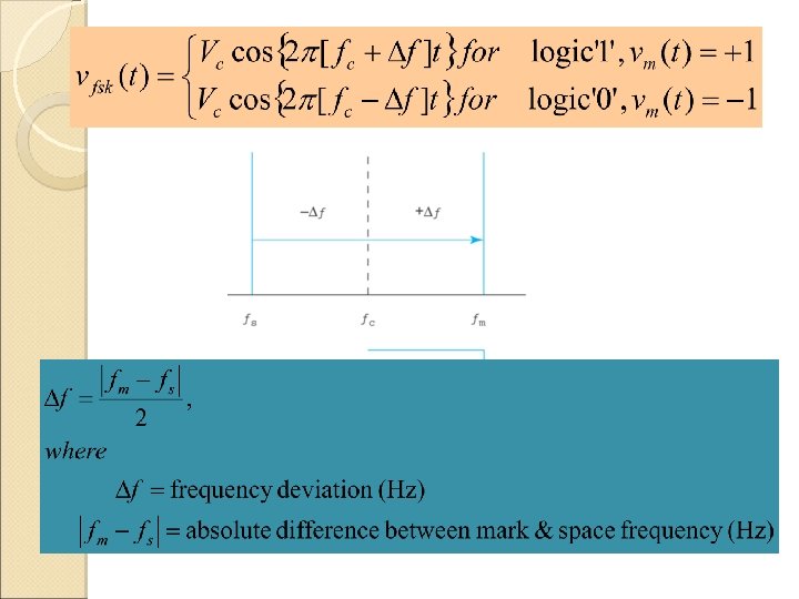
Frequency Shift Keying (FSK) Called as Binary Frequency Shift Keying (BFSK) The phase shift in carrier frequency (∆f) is proportional to the amplitude of the binary input signal (vm(t)) and the direction of the shift is determined by the polarity Where vfsk(t) = binary FSK waveform Vc = peak anlog carrier amplitude (volt) fc = analog carrier center frequency (Hz) ∆f = peak shift in analog carrier frequency (Hz) vm(t) = binary input signal (volt)
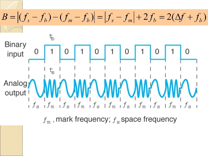
Frequency Shift Keying (FSK) Similar to the standard frequency modulation (FM) except the modulating signal is binary signal that varies between two discrete voltage levels rather than a continuously changing analogue waveform. FSK waveform : Figure 4. 9: FSK in the time domain: (a) waveform, (b) truth table.
Frequency Shift Keying (FSK) As the binary input signal changes from a logic 0 to a logic 1 and vice versa, the output frequency shifts between two frequencies: a mark, or logic 1 frequency (fm), and a space, or logic 0 frequency (fs). When the binary input (fb) changes from a logic 1 to a logic 0 and vice versa, the FSK output frequency shifts from a mark (fm) to a space (fs) frequency and vice versa. In Figure 4. 9(a), the mark frequency is the higher frequency (fc + Δf) and the space frequency is the lower frequency (fc - Δf), although this relationship could be just the opposite. Figure 4. 9(b) shows the truth table for a binary FSK modulator. The truth table shows the input and output possibilities for a given digital modulation scheme.
Frequency Shift Keying (FSK) Advantages of FSK over ASK : 1. ASK needs automatic gain 2. 3. control (AGC) to overcome fading effects. Easy for generation of FSK. The constant amplitude property of the carrier signal does not waste power and produce some immunity to noise.
Phase Shift Keying (PSK) PSK is an M-ary digital modulation scheme similar to conventional phase modulation except that in PSK the input signal is a binary digital signal and a limited number of output phases are possible. The simplest form of PSK is binary phase shift keying (BPSK). In BPSK, two outputs are possible for a single carrier (“binary” meaning “ 2”) i. e. , where N(input bits) = 1 and M(output phase) = 2. Therefore, with BPSK, two phases (21 = 2) are possible for the carrier. One output phase represents a logic 1 and the other a logic 0, i. e. , one phase represents logic 1 and the other phase represents a logic 0. As the input digital signal changes state (i. e. , from a 1 to a 0 or from a 0 to a 1), the phase of the output
(b) (a) Figure 4. 9: BPSK in the time domain: (a) waveform, (b) truth table.
Cont’d. . . a) Truth Table b) Phasor Diagram c) Constellation Diagram
Cont’d. . . BPSK Transmitter
Cont’d. . . BPSK Receiver
Quadrature-Amplitude Modulation (QAM) Quadrature-amplitude modulation (QAM) is a form of digital modulation similar to PSK except the digital information is contained in both the amplitude and the phase of the transmitted carrier. 8 -QAM is an M-ary encoding technique where M = 8. Unlike 8 -PSK, the output signal from an 8 -QAM modulator is not a constant-amplitude signal. Figure 4. 17 shows the output phase-versus-time relationship for an 8 -QAM modulator. Note that there are two output amplitudes, and only four phases are possible.
(a) (b) Figure 4. 17: (a) 8 -QAM modulator: output phase-versus-time relationship. (b) Truth table
Example 1 For the digital message 1101 1100 1010, sketch the waveform for the following: a. ASK b. FSK c. PSK d. QAM