Chapter 37 Section Layout Introduction Drawing sections is


 • Minimum of two full sections is required")


 • Continuous members – Diagonal")


- Slides: 21
Chapter 37 Section Layout
Introduction • Drawing sections is accomplished in seven major stages – Follow the step-by-step procedures • Sections can be easily drawn and understood • Read through each stage, and carefully compare the instructions with the corresponding illustrations
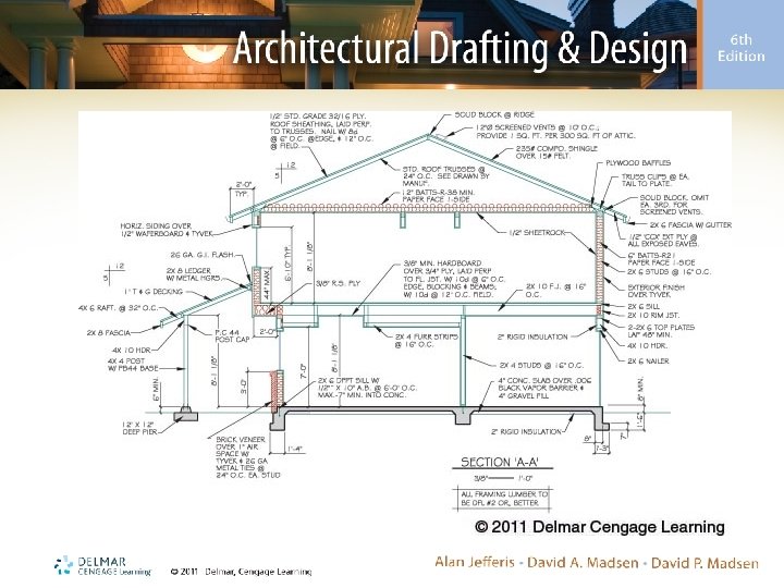
Stage 1: Evaluate Needs • Differences in required construction include: – Right side of the plan is one story, and left side is two story – Rear at right is a stick floor, and front is a concrete slab – Left side of the roof is a vaulted truss, and right side is a standard truss
Stage 1: Evaluate Needs (cont’d. ) • Minimum of two full sections is required to provide needed information – One cuts through the family room and kitchen • Shows concrete floor, walls, upper-floor cantilever, and truss roof – A full section is needed through the garage • Shows concrete and wooden floor construction – Partial sections show stairs and vaulted roof over bedroom 1
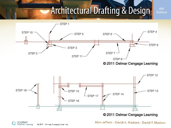
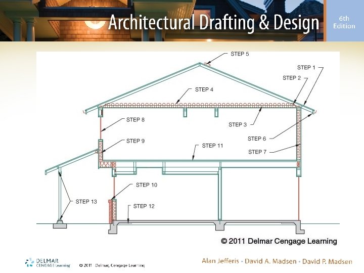
Stage 2: Lay Out the Section • Use construction lines for entire stage – Use a nonreproducible blue pencil or a 6 H lead • If working with Auto. CAD, place materials on a layer (e. g. , OUTL) • Section includes layouts for: – Concrete slab foundations – Walls – Truss roof
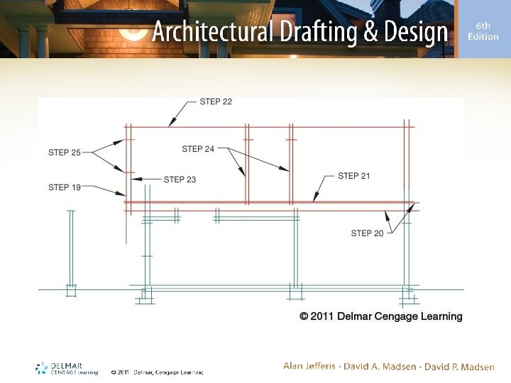
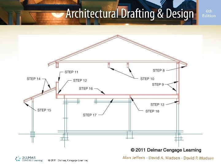
Stage 3: Finished-Quality Lines for Structural Members Only • Drawing with finished-quality lines – Start at the roof and work down • Steps followed are divided into: – Truss roof – Walls – Upper walls and floor – Lower walls – Foundation
Stage 3: Finished-Quality Lines for Structural Members (cont’d. ) • Continuous members – Diagonal cross (X) in the member • Blocking – One diagonal line (/) through the member • Members are also be drawn with different line qualities – Thin, bold, and very bold
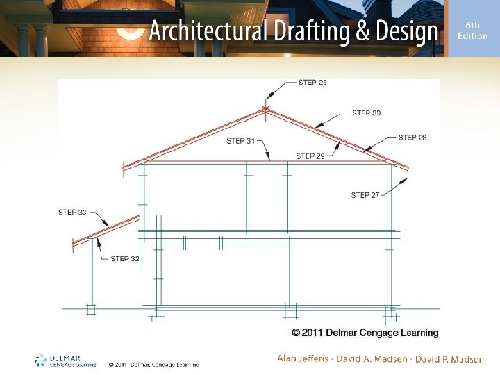
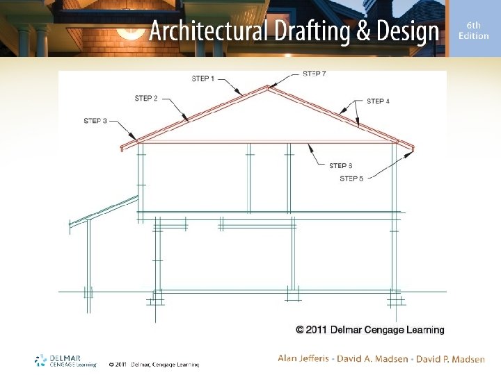
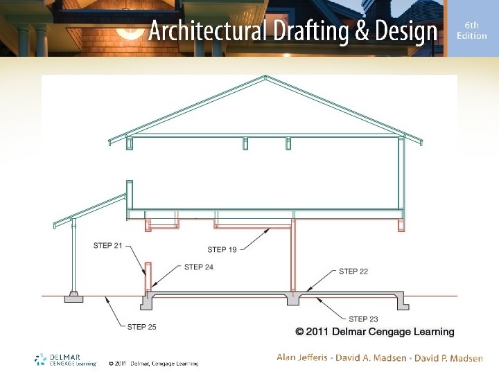
Stage 4: Drawing Finishing Materials • Material drawn in this stage seals exterior from weather and finishes the interior – Start at the roof and work down to foundation – Use thin lines for this stage unless otherwise noted
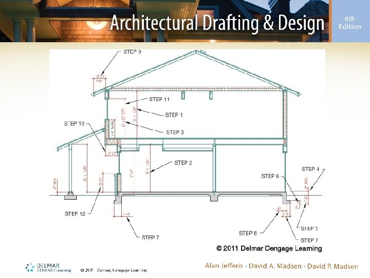
Stage 5: Dimensioning • Leader lines should be thin • Lettering should be aligned – If using Auto. CAD, place dimensions using the DIM command ANNOTATIVE feature
Stage 6: Lettering Notes • Place guidelines around drawing perimeter – Align required notes on the guidelines • Typically, the primary section will be fully notated, and other sections will have supplemental notes – General notes are included for: • Roof • Walls • Upper floor and foundation
Stage 7: Evaluating Your Work • Run a print, and evaluate it for accuracy and quality – Compare with someone else’s – Use a checklist – Get away from the drawing for an hour or two and then go back to it
Section-Trusses Checklist • Refer to the text for a complete truss checklist, including: – Plotting – Drawing – Dimensions