Chapter 36 Sectioning Basics Introduction Sections Drawn to

Chapter 36 Sectioning Basics

Introduction • Sections – Drawn to show vertical relationships of structural materials • Show methods of construction for framing crew – Before drawing, it is important to understand: • Different types of sections • Common scales • Relationship of cutting plane to the section

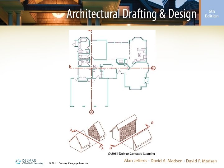
Section Origination • Building sections – Result of passing the viewing plane through a structure to reveal construction methods used • Material in front of viewing plane cannot be seen • Material behind viewing plane is projected to the plane and reproduced in the section
 • Another visualization method – Think of the viewing plane")
Section Origination (cont’d. ) • Another visualization method – Think of the viewing plane as a giant saw that slices vertically through a structure and divides it into two portions • One portion is removed to allow viewing of the portion that remains
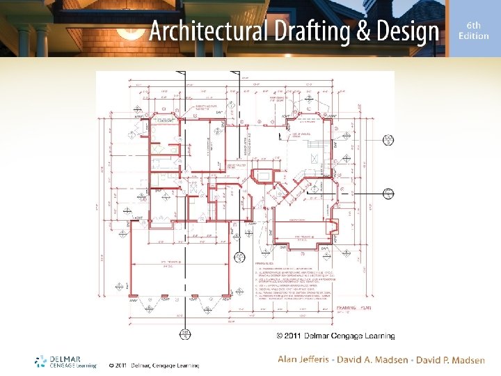

Section Alignment • Drawing is read from the bottom or right side of the page – Cutting plane • Shows which way the section is being viewed • Arrows should be pointing to the top or left side of the paper • If possible, should extend through entire structure • Can be broken for notes or dimensions • Can be jogged to show material clearly

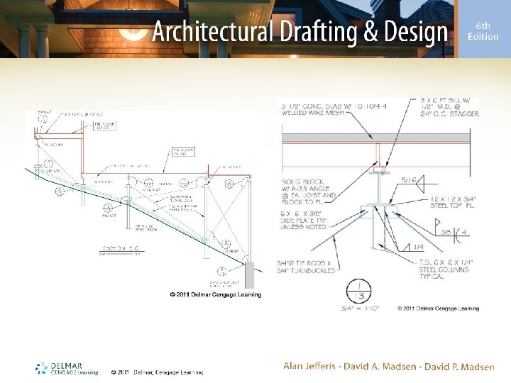
Types of Sections • Full sections – View that result from passing the cutting plane through the entire structure – Meant to give an overall view of a specific area • Transverse section • Longitudinal section
 • Partial sections – A section that does not")
Types of Sections (cont’d. ) • Partial sections – A section that does not go completely through the structure – Used to show construction materials for specific areas of the structure • Typically used to supplement full sections • Also used on complex structures as a reference for details of complicated areas
 • Details – Enlargements of specific areas of a")
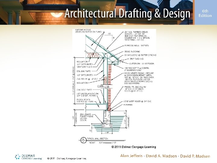
Types of Sections (cont’d. ) • Details – Enlargements of specific areas of a structure – Typically drawn where several components intersect or where small members are required

Drawing Scale • Sections are typically drawn at a scale of 3/8" = 1'– 0" – Scales of 1/8" or 1/4" may be used for supplemental sections requiring little detail – Partial section may be drawn at a scale of 3/8" = 1'– 0", 1/2" = 1'– 0", or 3/4" = 1'– 0 – Details are typically drawn at a scale of 1/2" = 1'– 0" through 3" = 1'– 0"
 • Factors that influence choice of scales in drawing sections:")
Drawing Scale (cont’d. ) • Factors that influence choice of scales in drawing sections: – Size of drawing sheet – Size of project – Placement of section – Purpose of section
 • Primary section – Typically drawn at a scale of")
Drawing Scale (cont’d. ) • Primary section – Typically drawn at a scale of 3/8" = 1'– 0" • Main advantage is ease of distinguishing each structural member • Other sections are drawn at 1/4" = 1'– 0" – By combining drawings at these two scales: • Typical information can be placed on 3/8" section • 1/4" sections show variations with little detail

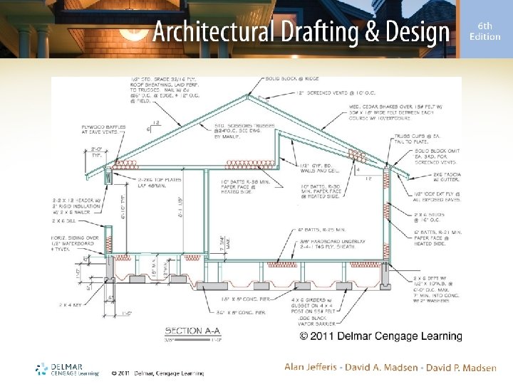
Representing and Locating Materials • Type of section drawn will dictate: – Amount of information displayed • Smaller the drawing scale, the less information – How the material will be represented • Details require more attention to line contrast and the use of more varied line weights
 • Using line contrast – Details require a")
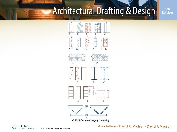
Representing and Locating Materials (cont’d. ) • Using line contrast – Details require a minimum of four different line weights to provide contrast between materials – Line weights vary depending on scale – Goal of each section is to have good contrast • Thin lines represent construction materials • Thick lines represent structural materials
 • Representing material – Method used depends on")
Representing and Locating Materials (cont’d. ) • Representing material – Method used depends on drawing scale • • • Wood, timber, and engineered products Steel Unit masonry Concrete Glazing Insulation
 • Locating materials with dimensions – Vertical and")
Representing and Locating Materials (cont’d. ) • Locating materials with dimensions – Vertical and horizontal dimensions may be placed on sections • Partial sections and details generally show only vertical dimensions • Small-scale sections use of dimensions depends on the area represented
 • Locating materials with dimensions (cont’d. ) –")
Representing and Locating Materials (cont’d. ) • Locating materials with dimensions (cont’d. ) – Vertical dimensions • Given from bottom of sole plate to top of the top plate for wood-frame structures • Steel stud walls • Structural steel • Masonry units • Concrete slab
 • Locating materials with dimensions (cont’d. ) –")
Representing and Locating Materials (cont’d. ) • Locating materials with dimensions (cont’d. ) – Horizontal dimensions • Use varies greatly • Usually not placed on partial sections or details, except for footing widths • Generally are located from grid lines to desired member
 • Drawing symbols – Symbols found on sections")
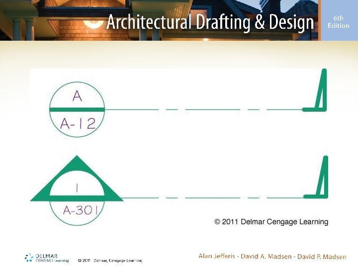
Representing and Locating Materials (cont’d. ) • Drawing symbols – Symbols found on sections include: • • • Grid markers Elevation markers Section markers Detail markers Room names and numbers
 • Drawing notations – Used to specify materials")
Representing and Locating Materials (cont’d. ) • Drawing notations – Used to specify materials and explain special installation procedures • Placed as either local or keyed notes • When possible, notes should be placed on exterior of the building • Smaller the scale, more generic the notes
- Slides: 26