CHAPTER 3 XRAY DIFFRACTION IN CRYSTAL I III


 An electron in a higher orbital immediately falls to")


 Transmission Method. Source of X-ray – emits a beams of continuous")

 Back Reflaction Method : This method provides similar information as above")


- Slides: 52
CHAPTER 3 X-RAY DIFFRACTION IN CRYSTAL I. III. IV. V. VI. Bertha Röntgen’s Hand 8 Nov, 1895 1 VII. X-Ray Diffraction of Waves by Crystals X-Ray Diffraction Bragg Equation X-Ray Methods Neutron & Electron Diffraction
X-RAY ¢ X-rays were discovered in 1895 by the German physicist Wilhelm Conrad Röntgen and were so named because their nature was unknown at the time. ¢ He was awarded the Nobel prize for physics in 1901. 2 Wilhelm Conrad Röntgen (1845 -1923)
X-RAY PROPERTIES ¢ X ray, invisible, highly penetrating electromagnetic radiation of much shorter wavelength (higher frequency) than visible light. The wavelength range for X rays is from about 10 -8 m to about 10 -11 m, the corresponding frequency range is from about 3 × 10¹⁶ Hz to about 3 × 10¹⁹ Hz. 3
4
X-RAY TUBE ¢ X rays can be produced in a highly evacuated glass bulb, called an X-ray tube, that contains essentially two electrodes—an anode made of platinum, tungsten, or another heavy metal of high melting point, and a cathode. When a high voltage is applied between the electrodes, streams of electrons (cathode rays) are accelerated from the cathode to the anode and produce X rays as they strike the anode. Evacuated glass bulb Cathode Anode 5
Monochromatic and Broad Spectrum of X-rays ¢ X-rays can be created by bombarding a metal target with high energy (> ) electrons. ¢ Some of these electrons excite electrons from core states in the metal, which then recombine, producing highly monochromatic X-rays. These are referred to as characteristic X-ray lines. ¢ Other electrons, which are decelerated by the periodic potential of the metal, produce a broad spectrum of X-ray frequencies. ¢ Depending on the diffraction experiment, either or both of these X-ray spectra can be used. 6
ABSORPTION OF X-RAYS ¢ The atoms that make up your body tissue absorb visible light photons very well. The energy level of the photon fits with various energy differences between electron positions. . something you won't see very often (Visible Light) ¢ Radio waves don't have enough energy to move electrons between orbitals in larger atoms, so they pass through most stuff. X-ray photons also pass through most things, but for the opposite reason: They have too much energy. X-ray 7
Generation of X-rays (K-Shell Knockout) An electron in a higher orbital immediately falls to the lower energy level, releasing its extra energy in the form of a photon. It's a big drop, so the photon has a high energy level; it is an X-ray photon. The free electron collides with the tungsten atom, knocking an electron out of a lower orbital. A higher orbital electron fills the empty position, releasing its excess energy as a photon. 8
Absorption of X-rays ¢ A larger atom is more likely to absorb an X-ray photon in this way, because larger atoms have greater energy differences between orbitals -- the energy level more closely matches the energy of the photon. Smaller atoms, where the electron orbitals are separated by relatively low jumps in energy, are less likely to absorb X-ray photons. ¢ The soft tissue in your body is composed of smaller atoms, and so does not absorb X-ray photons particularly well. The calcium atoms that make up your bones are much larger, so they are better at absorbing X-ray photons. 9
DIFFRACTION ¢ Diffraction is a wave phenomenon in which the apparent bending and spreading of waves when they meet an obstruction. ¢ Diffraction occurs with electromagnetic waves, such as light and radio waves, and also in sound waves and water waves. ¢ The most conceptually simple example of diffraction is double-slit diffraction, that’s why firstly we remember light diffraction. 10 Width b Variable (500 -1500 nm) Wavelength Constant (600 nm) Distance d = Constant
LIGHT DIFFRACTION ¢ Light diffraction is caused by light bending around the edge of an object. The interference pattern of bright and dark lines from the diffraction experiment can only be explained by the additive nature of waves; wave peaks can add together to make a brighter light, or a peak and a through will cancel each other out and result in darkness. Thus Young’s light interference experiment proves that light has wavelike properties. 11
Constructive & Destructive Waves ¢ Constructive interference is the result of synchronized light waves that add together to increase the light intensity. 13 ¢ Destructive İnterference. results when two out-of-phase light waves cancel each other out, resulting in darkness.
Light Interference 14
Diffraction from a particle and solid Single particle ¢ To understand diffraction we also have to consider what happens when a wave interacts with a single particle. The particle scatters the incident beam uniformly in all directions Solid material ¢ What happens if the beam is incident on solid material? If we consider a crystalline material, the scattered beams may add together in a few directions and reinforce each other to give diffracted beams 15
Diffraction of Waves by Crystals ¢ The structure of a crystal can be determined by studying the diffraction pattern of a beam of radiation incident on the crystal. ¢ Beam diffraction takes place only in certain specific directions, much as light is diffracted by a grating. ¢ By measuring the directions of the diffraction and the corresponding intensities, one obtains information concerning the crystal structure responsible for diffraction. 16
X-Ray Diffraction W. L. Bragg presented a simple explanation of the diffracted beams from a crystal. The Bragg derivation is simple but is convincing only since it reproduces the correct result. 17
X-Ray Diffraction & Bragg Equation ¢ English physicists Sir W. H. Bragg and his son Sir W. L. Bragg developed a relationship in 1913 to explain why the cleavage faces of crystals appear to reflect X-ray beams at certain angles of incidence (theta, θ). This observation is an example of X-ray wave interference. Sir William Henry Bragg (1862 -1942), William Lawrence Bragg (1890 -1971) o 1915, the father and son were awarded the Nobel prize for physics "for their services in the analysis of crystal structure by means of Xrays". 18
Bragg Equation ¢ ¢ Bragg law identifies the angles of the incident radiation relative to the lattice planes for which diffraction peaks occurs. Bragg derived the condition for constructive interference of the X-rays scattered from a set of parallel lattice planes. 19
BRAGG EQUATION ¢ ¢ W. L. Bragg considered crystals to be made up of parallel planes of atoms. Incident waves are reflected specularly from parallel planes of atoms in the crystal, with each plane is reflecting only a very small fraction of the radiation, like a lightly silvered mirror. In mirrorlike reflection the angle of incidence is equal to the angle of reflection. ө 20 ө
Diffraction Condition The diffracted beams are found to occur when the reflections from planes of atoms interfere constructively. ¢ We treat elastic scattering, in which the energy of X-ray is not changed on reflection. ¢ 21
Bragg Equation ¢ When the X-rays strike a layer of a crystal, some of them will be reflected. We are interested in X-rays that are in-phase with one another. X-rays that add together constructively in xray diffraction analysis in-phase before they are reflected and after they reflected. Incident angle Reflected angle Wavelength of X-ray 22 Total Diffracted Angle
Bragg Equation ¢ ¢ These two x-ray beams travel slightly different distances. The difference in the distances traveled is related to the distance between the adjacent layers. Connecting the two beams with perpendicular lines shows the difference between the top and the bottom beams. The line CE is equivalent to the distance between the two layers (d) 23
Bragg Law ¢ The length DE is the same as EF, so the total distance traveled by the bottom wave is expressed by: ¢ Constructive interference of the radiation from successive planes occurs when the path difference is an integral number of wavelenghts. This is the Bragg Law. 24
Bragg Equation where, d is the spacing of the planes and n is the order of diffraction. ¢ Bragg reflection can only occur for wavelength ¢ This is why we cannot use visible light. No diffraction occurs when the above condition is not satisfied. ¢ The diffracted beams (reflections) from any set of lattice planes can only occur at particular angles pradicted by the Bragg law. 25
Scattering of X-rays from adjacent lattice points A and B X-rays are incident at an angle on one of the planes of the set. There will be constructive interference of the waves scattered from the two successive lattice points A and B in the plane if the distances AC and DB are equal. 26
Constructive interference of waves scattered from the same plane If the scattered wave makes the same angle to the plane as the incident wave The diffracted wave looks as if it has been reflected from the plane We consider the scattering from lattice points rather than atoms because it is the basis of atoms associated with each lattice point that is the true repeat unit of the crystal; The lattice point is analoque of the line on optical diffraction grating and the basis represents the structure of the line. 27
Diffraction maximum Coherent scattering from a single plane is not sufficient to obtain a diffraction maximum. It is also necessary that successive planes should scatter in phase This will be the case if the path difference for scattering off two adjacent planes is an integral number of wavelengths ¢ 28
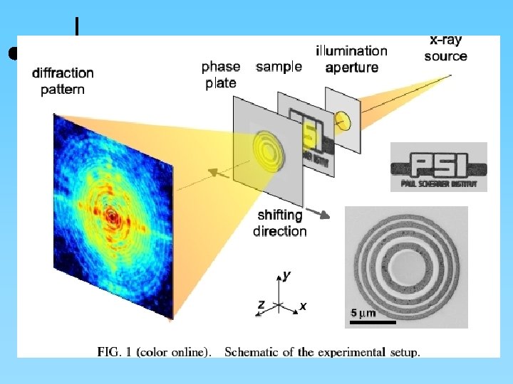
Experimental arrangements for x-ray diffraction ¢ Since the pioneering work of Bragg, x-ray diffraction has become into a routine technique for the determination of crsytal structure. 29
Bragg Equation Since Bragg's Law applies to all sets of crystal planes, the lattice can be deduced from the diffraction pattern, making use of general expressions for the spacing of the planes in terms of their Miller indices. For cubic structures Note that the smaller the spacing the higher the angle of diffraction, i. e. the spacing of peaks in the diffraction pattern is inversely proportional to the spacing of the planes in the lattice. The diffraction pattern will reflect the symmetry properties of the lattice. 30
Types of X-ray camera 1. 2. 3. There are many types of X-ray camera to sort out reflections from different crystal planes. We will study only three types of X-ray photograph that are widely used for the simple structures. Laue photograph Rotating crystal method Powder photograph 31
X-RAY DIFFRACTION METHODS X-Ray Diffraction Method Laue Rotating Crystal Powder Orientation Single Crystal Polychromatic Beam Fixed Angle Lattice constant Single Crystal Monochromatic Beam Variable Angle Lattice Parameters Polycrystal (powdered) Monochromatic Beam Variable Angle 32
¢ Laue Method It include two methodes. 1. Transmission method & 2. Back reflection method.
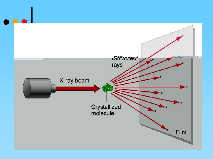
( 1 ) Transmission Method. Source of X-ray – emits a beams of continuous wave length, known as White Radiation. Which is obtained from a Tungsten target at about 60, 000 volts. Pinhole collimator – When X-ray obtain from source, allowed to pass through this Pinhole a fine pencil of X-ray is obtain. The smaller is the diameter, the Sharper is the Interference. Sample holder - Crystal is set on holder to adjust its orientation. Position of crystal is held stationary in a beam of X-ray. The x-ray passing through the crystal are diffracted & recorded on a photographic plate.
¢ Photographic plate.
( 2 ) Back Reflaction Method : This method provides similar information as above one. It only use for investigation of Large & thick specimens.
¢ In the back-reflection method, the film is placed between the x -ray source and the crystal. The beams which are diffracted in a backward direction are recorded.
Transmission Laue Method ¢ In the transmission Laue method, the film is placed behind the crystal to record beams which are transmitted through the crystal. ¢ One side of the cone of Laue reflections is defined by the transmitted beam. The film intersects the cone, with the diffraction spots generally lying on an ellipse. X-Ray 39 Single Crystal Film
ROTATING CRYSTAL METHOD ¢ In the rotating crystal method, a single crystal is mounted with an axis normal to a monochromatic x-ray beam. A cylindrical film is placed around it and the crystal is rotated about the chosen axis. ¢ As the crystal rotates, sets of lattice planes will at some point make the correct Bragg angle for the monochromatic incident beam, and at that point a diffracted beam will be formed. 40
ROTATING CRYSTAL METHOD Lattice constant of the crystal can be determined by means of this method; for a given wavelength if the angle at which a reflection occurs is known, can be determined. 41
Rotating Crystal Method The reflected beams are located on the surface of imaginary cones. By recording the diffraction patterns (both angles and intensities) for various crystal orientations, one can determine the shape and size of unit cell as well as arrangement of atoms inside the cell. Film 42
THE POWDER METHOD If a powdered specimen is used, instead of a single crystal, then there is no need to rotate the specimen, because there will always be some crystals at an orientation for which diffraction is permitted. Here a monochromatic Xray beam is incident on a powdered or polycrystalline sample. This method is useful for samples that are difficult to obtain in single crystal form. 43
THE POWDER METHOD The powder method is used to determine the value of the lattice parameters accurately. Lattice parameters are the magnitudes of the unit vectors a, b and c which define the unit cell for the crystal. For every set of crystal planes, by chance, one or more crystals will be in the correct orientation to give the correct Bragg angle to satisfy Bragg's equation. Every crystal plane is thus capable of diffraction. Each diffraction line is made up of a large number of small spots, each from a separate crystal. Each spot is so small as to give the appearance of a continuous line. 44
Debye Scherrer Camera A very small amount of powdered material is sealed into a fine capillary tube made from glass that does not diffract x-rays. The specimen is placed in the Debye Scherrer camera and is accurately aligned to be in the centre of the camera. X-rays enter the camera through a collimator. 45
Debye Scherrer Camera The powder diffracts the x-rays in accordance with Braggs law to produce cones of diffracted beams. These cones intersect a strip of photographic film located in the cylindrical camera to produce a characteristic set of arcs on the film. 46
Powder diffraction film When the film is removed from the camera, flattened and processed, it shows the diffraction lines and the holes for the incident and transmitted beams. 47
48
different views of the Debye-Scherrer Camera 49
Application of XRD is a nondestructive technique. Some of the uses of x -ray diffraction are; 1. 2. 3. 4. 5. 6. Differentiation between crystalline and amorphous materials; Determination of the structure of crystalline materials; Determination of electron distribution within the atoms, and throughout the unit cell; Determination of the orientation of single crystals; Determination of the texture of polygrained materials; Measurement of strain and small grain size…. . etc 50
Advantages and disadvantages of X-rays Advantages; ¢ ¢ X-ray is the cheapest, the most convenient and widely used method. X-rays are not absorbed very much by air, so the specimen need not be in an evacuated chamber. Disadvantage; ¢ 51 They do not interact very strongly with lighter elements.
52 Schematic diagram of Debye Scherrer Camera