Chapter 3 Voltage and Current Laws Fig 3

 A circuit containing three nodes and five branches. (b) Node 1 is redrawn")

 Series connected voltage sources can be replaced by a single source. (b) Parallel")

 Series combination of N resistors. (b) Electrically equivalent circuit. W. H. Hayt, Jr.")


- Slides: 17
Chapter 3 Voltage and Current Laws Fig. 3. 1 “A circuit containing three nodes and five branches …” Fig. 3. 2 Example node to illustrate the application of KCL. User Note: Fig. 3. 19 “Addition of multiple voltage or current sources. ” Run View Show under the Slide Show menu to enable slide selection. Fig. 3. 20 Examples of circuits with multiple sources, . . . Fig. 3. 22 (a) Series combination of N resistors. Fig. 3. 25 (a) A circuit with N resistors in parallel. Fig. 3. 30 An illustration of voltage division. Fig. 3. 32 Circuit for Practice Problem 3. 12. Fig. 3. 33 An illustration of current division. Fig. 3. 100 “Determine the current Ix if I 1 = 100 m. A. ” Engineering Circuit Analysis Sixth Edition W. H. Hayt, Jr. , J. E. Kemmerly, S. M. Durbin Copyright © 2002 Mc. Graw-Hill, Inc. All Rights Reserved.
(a) A circuit containing three nodes and five branches. (b) Node 1 is redrawn to look like two nodes; it is still one node. W. H. Hayt, Jr. , J. E. Kemmerly, S. M. Durbin, Engineering Circuit Analysis, Sixth Edition. Copyright © 2002 Mc. Graw-Hill. All rights reserved.
Figure 3. 2 W. H. Hayt, Jr. , J. E. Kemmerly, S. M. Durbin, Engineering Circuit Analysis, Sixth Edition. Copyright © 2002 Mc. Graw-Hill. All rights reserved.
(a) Series connected voltage sources can be replaced by a single source. (b) Parallel current sources can be replaced by a single source. W. H. Hayt, Jr. , J. E. Kemmerly, S. M. Durbin, Engineering Circuit Analysis, Sixth Edition. Copyright © 2002 Mc. Graw-Hill. All rights reserved.
Examples of circuits with multiple sources, some of which are “illegal” as they violate Kirchhoff’s laws. W. H. Hayt, Jr. , J. E. Kemmerly, S. M. Durbin, Engineering Circuit Analysis, Sixth Edition. Copyright © 2002 Mc. Graw-Hill. All rights reserved.
(a) Series combination of N resistors. (b) Electrically equivalent circuit. W. H. Hayt, Jr. , J. E. Kemmerly, S. M. Durbin, Engineering Circuit Analysis, Sixth Edition. Copyright © 2002 Mc. Graw-Hill. All rights reserved.
Beginning with a simple KCL equation, or Thus, A special case worth remembering is (a) A circuit with N resistors in parallel. (b) Equivalent circuit. W. H. Hayt, Jr. , J. E. Kemmerly, S. M. Durbin, Engineering Circuit Analysis, Sixth Edition. Copyright © 2002 Mc. Graw-Hill. All rights reserved.
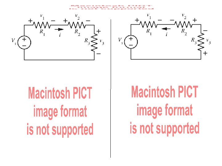
We may find v 2 by applying KVL and Ohm’s law: so An illustration of voltage division. Thus, or For a string of N series resistors, we may write: W. H. Hayt, Jr. , J. E. Kemmerly, S. M. Durbin, Engineering Circuit Analysis, Sixth Edition. Copyright © 2002 Mc. Graw-Hill. All rights reserved.
Use voltage division to determine vx in the adjacent circuit. W. H. Hayt, Jr. , J. E. Kemmerly, S. M. Durbin, Engineering Circuit Analysis, Sixth Edition. Copyright © 2002 Mc. Graw-Hill. All rights reserved.
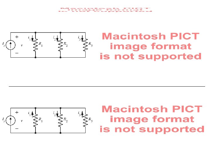
The current flowing through R 2 is or An illustration of current division. For a parallel combination of N resistors, the current through Rk is W. H. Hayt, Jr. , J. E. Kemmerly, S. M. Durbin, Engineering Circuit Analysis, Sixth Edition. Copyright © 2002 Mc. Graw-Hill. All rights reserved.
Determine the current Ix if I 1 = 100 m. A. W. H. Hayt, Jr. , J. E. Kemmerly, S. M. Durbin, Engineering Circuit Analysis, Sixth Edition. Copyright © 2002 Mc. Graw-Hill. All rights reserved.