Chapter 3 Single Phase Synchronous Motors The 3


 Eddy current torque due")

 when the motor stalls, the rotating field moves at 225 rpm with respect")
- Slides: 17
Chapter 3 Single Phase Synchronous Motors § The 3 -phase synchronous motors are usually large machines of the order of several hundred kilowatts or megawatts. § However, many low-power applications require constant speed. § Single phase synchronous motors of small ratings are ideally suited to such applications as clocks, timers, and turntables.
§ Two types of small synchronous motors are used, reluctance motors and hysteresis motors. § These motors do not require dc field excitation, or permanent magnets. Therefore they are simple in construction. Single-phase Reluctance Motors : • It is the same as the single-phase induction motor except that some saliency is introduced in the rotor structure to provide the required number of poles.
§ The reluctance motor starts as a squirrel-cage induction motor and accelerates towards synchronous speed. § At a “critical” speed, the saliency of the motor will cause a reluctance torque to be developed and rotates in synchronism with the rotating flux. §The reluctance torque arises from the tendency of the rotor to align itself with the rotating field.
§ at no load, The two magnetic axes of the stator and rotor are nearly aligned. § A “step” increase in load slows the rotor down, and the rotor poles “lag” the stator poles. § The angle of lag, δ, is called the “torque angle”. § The maximum torque angle, δmax is equal to 45°.
• If load increases so that δ>45°, the flux path is “over stretched” and the rotor falls out of synchronism. Reluctance torque
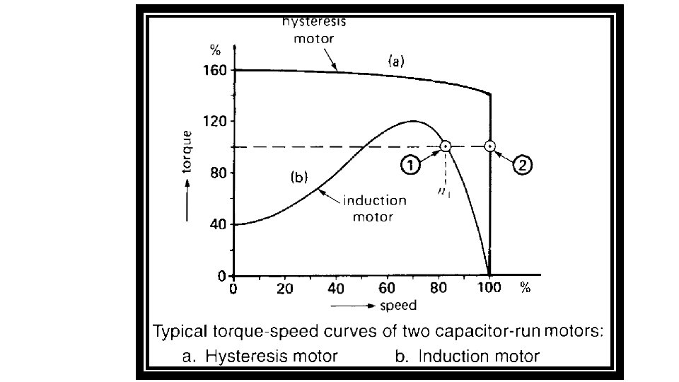
Torque / speed characteristic of the single-phase reluctance motor:
Characteristics q The reluctance motor has a low power factor because it requires a large amount of reactive current for its excitation. q The absence of dc excitation in the rotor greatly reduces the max. torque. q A reluctance motor is several times larger than a synchronous motor with dc excitation having the same horsepower and speed ratings. q In some applications these disadvantages may be offset by simplicity of construction (no slip rings, no brushes, and no dc field winding), low cost, and practically maintenance-free operation.
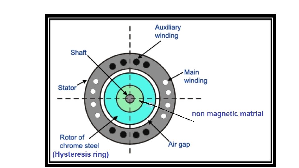
Hysteresis Motors • Hysteresis motor is a synchronous motor having cylindrical rotor and use the hysteresis property of magnetic material to produce torque. § The stator windings are normally of the capacitor-run type to produce rotating field. § The rotor composed of ceramic magnetic material having high coercive force and high resistivity. It is mounted on a cylinder of nonmagnetic material.
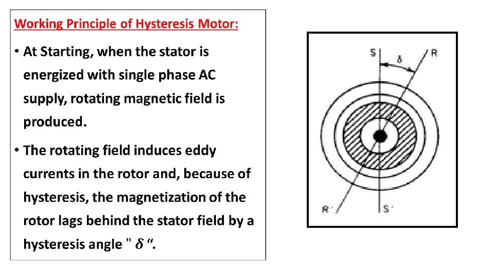
• The starting torque consists of two components: a) Eddy current torque due to the interaction between the stator field and the rotor eddy currents. b) Hysteresis torque due to the hysteresis loss property of the rotor magnetic material with high retentiveity (residual magnetism). • When the speed of the rotor reaches near the synchronous speed, the stator pulls the rotor into synchronism. • At synchronous speed, the torque due to eddy currents vanishes, and the motor rotates by the hysteresis torque only.
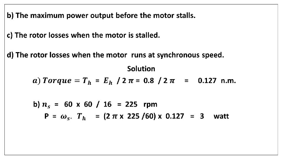
Applications: § The hysteresis motor is employed in electric clocks, and other precise timing devices. § It is also used to drive tape decks, turntables, and other precision audio equipment. Example: A small 60 Hz hysteresis clock motor possesses 32 poles. In making one complete turn with respect to the rotating field , the hysteresis loss in the rotor amounts to 0. 8 Joule. Calculate: a) The pull in and pull out torque.
c) when the motor stalls, the rotating field moves at 225 rpm with respect to the rotor. The energy loss / minute is : W = 225 x 0. 8 = 180 Joule P = 180 / 60 = 3 watt d) There is no energy loss in the rotor when the motor runs at synchronous speed.