CHAPTER 3 NC Tooling and Machining Processes Prepared

 Ability to explain the concept and evaluate the requirements")

 • How do you identify what type of cutting tool")


 Milling operations: pocketing, contouring, facing and side milling")
 • Drilling: Is often considered as roughing operation because")
 Common hole-making operations")
 Turning Operations: Profiling, ID boring, grooving or parting, OD")

 • Thermal conditioning: – Heat treatment: tempering (adjust steel hardness),")
 Machinability of common materials Material Machinability Index 1112 Steel 100%")

 High-Speed Steel (HSS) • HSS is inexpensive and can handle")
 • Carbides tool grades: - ANSI-standard C shows some of")


 Example: CNMG-432 Code *Refer Table 4.")
 • Ex o tic tool materials (e. g. , polycrystalline")
 • Tool coatings ( A thin-film coating): – Protect against")


 • Insert-tooth cutting tools: – Tough steel body")
 • Spindles: hold cutting tool and rotate by")
 Spindle tooling: drill chuck, collet chuck, chuck and")
 A collet chuck is used to secure drills,")

 Single-point turning tools: boring, ID threading,")
 Turning tools are manufactured in a")

 A milling vise is the versatile")
 Different workstop configurations used to locate the workpiece on a single")
 Strap clamps")

 A hydraulically actuated lathe chuck with soft jaws bored to accommodate")

- Slides: 42
CHAPTER 3 NC Tooling and Machining Processes Prepared by: Ahmad Fairuz Bin Mansor Universiti Malaysia Perlis (Uni. MAP) 2017
Course Outcome 1 (CO 1) Ability to explain the concept and evaluate the requirements of NC machining operation such as workpiece zero setting, tool setting, etc.
Essential Questions • What are the basic machining processes? • What are some of the more common materials used in the machining industry today and how does their composition affect machining? • What types of cutting tools are used in CNC machining?
Essential Questions (cont’d. ) • How do you identify what type of cutting tool to use? • What are some of the workholding tools used?
CNC and Manufacturing Processes • CNC systems are used in: – Machining • Most established and important use. • Material removal process. • Hardened cutting tool is used to remove chips from workpiece. • Chips are formed by pushing a hardened tool into softer workpiece until material deforms. – Forming – Fabrication
Basic Machining Operations • Milling: – Rotating tool removes material along a contour or line • Turning: – Machining operations performed on a lathe – Tool is held stationary while part is rotated • Results in a cylindrical shape • Drilling and reaming: – Hole-making operations
Basic Machining Operations (cont’d. ) Milling operations: pocketing, contouring, facing and side milling
Basic Machining Operations (cont’d. ) • Drilling: Is often considered as roughing operation because of the vary nature of the cutting tool that is used. • Reaming: Reaming is a finishing operation performed with a multi-edge tool giving high-precision holes. An operation similar to drilling but produces a higher quality hole very quickly. • Boring: • Internal turning process performed on lathe or milling machine boring head • Tapping: Production of internal threads with a tool that is ground in the form of the finished thread. The process of cutting or forming threads using a tap is called tapping, whereas the process using a die is called threading.
Basic Machining Operations (cont’d. ) Common hole-making operations
Basic Machining Operations (cont’d. ) Turning Operations: Profiling, ID boring, grooving or parting, OD turning, threading and facing
Material Considerations • Common engineering materials in the machine shop include: – Metals: • Steel, stainless steel, cast iron, copper alloys, aluminum, magnesium, zinc, titanium and nickel alloys – Plastics (polymers) – Composites
Material Considerations (cont’d. ) • Thermal conditioning: – Heat treatment: tempering (adjust steel hardness), annealing (cool slowly) • Work hardening: – Rolling or drawing material to change shape • Free-cutting steels: – Lead and sulfur (make steel easier to machine) – Spherodizing (change steel structure) • Machinability - Machinability is a property that express the effort that is needed to remove material through a chip-making process.
Material Considerations (cont’d. ) Machinability of common materials Material Machinability Index 1112 Steel 100% 1018 Steel 77% 4130 Steel 72% 4140 Steel 62% 06 Tool Steel 48% D 2 Tool Steel 25% 304 Stainless Steel 45% 316 Stainless Steel 45% Aluminum 175% Brass 150% Titanium 40% Inconel (Nickel Superalloy) 15%
Cutting Tools • Instruments that make contact with the workpiece and produce the chips. • Common cutting tool materials: – High-speed steel (HSS). – Cemented carbides. • Grades based on ISO system. • Programmer must specify style of insert to use in a CNC machining job.
Cutting Tools (cont’d. ) High-Speed Steel (HSS) • HSS is inexpensive and can handle a great amount of shock. • Drills, end mils and taps are commonly made from HSS. Cemented Carbides • Carbides are more expensive and brittle that difficult for situation which subjected to shock and vibration. • Carbides are available in several grades (composition and hardness). • The grading systems is a continuum from soft/tough to hard/brittle. • Typically, cutting speed for carbide tools is four to seven times that of HSS. • The properties of cemented carbides can be manipulated by varying the ratio of cobalt binder to carbide and by using different metallic carbides.
Cutting Tools (cont’d. ) • Carbides tool grades: - ANSI-standard C shows some of the commercially available carbide grades. - ISO system have become more prevalent in recent years. It defines the intended use of a carbide tool material.
Table 4. 4 Common Indexable Insert Shapes
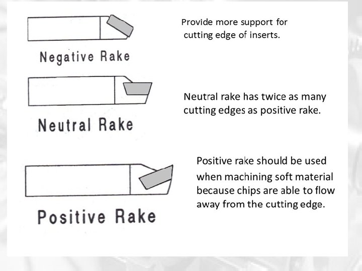
Tool holders and inserts are available in numerous styles that can be adapted to the machining job: -Insert with acute angle for intricate profile. -Insert with obtuse angle for straight sections and faces.
• Negative rake angle: - Tend to cause higher cutting forces and deflection. - Most application are used. • Positive rake angle: - Tend to cause lower cutting forces and deflection. - Is used when setup is not rigid like to make small boring. And use for finishing purpose. - Need sharp corner and relief that tend to fracture easily.
ANSI standard Identification code for indexable insert
ANSI standard Identification code for indexable insert (cont’d) Example: CNMG-432 Code *Refer Table 4. 5 for reference Description C The insert has an 80˚ diamond shape N The relief angle is 0˚. This indicates that this insert is used at a negative rake M This mid-range tolerance class is used for most applications G The insert has a hole in the centre for mounting and a chip breaker molded into the insert 4 The inscribed circle is 4/8 or 0. 500”. An inscribed circle is the smallest circle that will fit completely within the inside shape of the insert. 3 The thickness is 3/16 or 0. 1875”. 2 The nose radius is 1/32 or 0. 0313”.
Cutting Tools (cont’d. ) • Ex o tic tool materials (e. g. , polycrystalline diamond (PCD), Cubic boron nitride (CBN), Silicone nitride (SN): – Tough specialty applications – Ex p ensive • PCD is a synthetic diamond material that used for machining nonferrous metal. • CBN is a synthetic material that used for machining hardened steel. • SN is a ceramic material that is used primarily to machine highly abrasive material. Generally more expensive than ferrous metals, non-ferrous metals are used because of desirable properties such as low weight (e. g. aluminium), higher conductivity (e. g. copper), non-magnetic property or resistance to corrosion (e. g. zinc). Some non-ferrous materials are also used in the iron and steel industries.
Cutting Tools (cont’d. ) • Tool coatings ( A thin-film coating): – Protect against wear from rubbing (might affect by abrasive action and heat-generation). – Usually use Titanium nitride (Ti. N). It has low coefficient of friction which result in a lower temperature at cutting edge. – Lower layer of Ti. N is Aluminum Oxide that very hard material to help prolong tool life. – Under layer of Ti. N is titanium carbonitride that perform similar with Ti. N. • Processes used for coating are: - Physical Vapor Deposition (PVD) - Chemical vapor Deposition (CVD)
Tool coatings
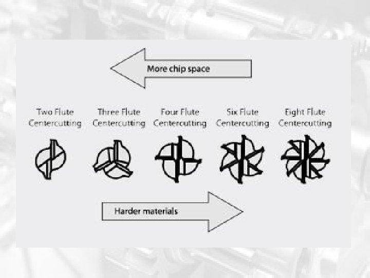
Cutting Tools for Milling • End mill: – Designed to cut on both the end and the side Table 4. 7 Comparison of End Mill Designs
Cutting Tools for Milling (cont’d. ) • Insert-tooth cutting tools: – Tough steel body – Hard carbide cutting edges – Carbide inserts are thrown away Figure 4. 18 Insert-tooth face and end mills.
Cutting Tools for Milling (cont’d. ) • Spindles: hold cutting tool and rotate by means of an electric motor – Caterpillar (CAT), or Vflange, and BT – End mill adapter most common Figure 4. 19 Tool adapters for the most common spindle styles.
Cutting Tools for Milling (cont’d. ) Spindle tooling: drill chuck, collet chuck, chuck and collet, end mill adapter and boring head. A collet /ˈkɒlɪt/ is a subtype of chuck that forms a collar around an object to be held and exerts a strong clamping force on the object when it is tightened, usually by means of a tapered outer collar. It may be used to hold a workpiece or a tool.
Cutting Tools for Milling (cont’d. ) A collet chuck is used to secure drills, reamers and end mills.
Cutting Tools for Turning and Hole Cutting • For turning: – Outside diameter turning tools – Boring bars – Most common holding method is mounting in a turret • For hole cutting: – Drills and reamers – Boring head
Cutting Tools for Turning and Hole Cutting (cont’d) Single-point turning tools: boring, ID threading, ID grooving, OD profiling, OD turning, OD threading.
Cutting Tools for Turning and Hole Cutting (cont’d) Turning tools are manufactured in a variety of orientations for turning from any direction
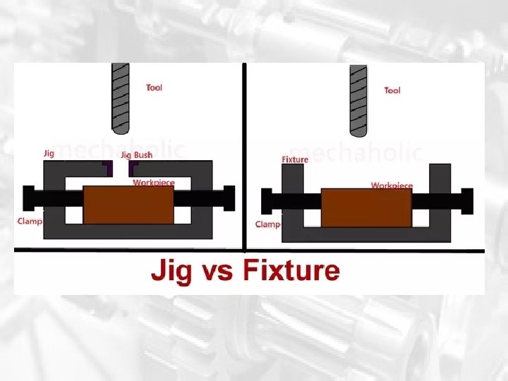
Workholding Tooling • Securing workpiece while machining – Milling vise – Clamping devices – Fi x t uring • For CNC lathe: – Chuck is the most common Figure 4. 27 Clamping forces create enough friction to resist the cutting forces and hold the workpiece in place.
Workholding Tooling (cont’d) A milling vise is the versatile
Workholding Tooling (cont’d) Different workstop configurations used to locate the workpiece on a single a reference point.
Workholding Tooling (cont’d) Strap clamps
Figure 4. 33 Modular fixturing components showing a variety of locating tooling and clamping tooling. Courtesy of Carr Lane.
Workholding Tooling (cont’d) A hydraulically actuated lathe chuck with soft jaws bored to accommodate workpiece.
The End Q&A