Chapter 3 Coordinate systems A coordinate system is


 Projections")
 the")
 grid coordinate")
 projection map")
 projection map")


 – Not actually a projection,")
 Based on Secant transverse cylindrical projection Divides up Earth’s surface")
 mapping of the")
- Slides: 21
Chapter 3 - Coordinate systems A coordinate system is a grid used to identify locations on a page or screen that are equivalent to grid locations on the globe The coordinates are (x, y) pairs that are based on some universal origin point for reference. The most commonly used is latitude and longitude
Latitude and longitude refer to degree, minutes and seconds of arc from reference lines that run East-West (latitude; equator) or North-South (longitude; prime meridian)
The reference datum is referred to in the coordinate system, typically by the year and the geographic region that it was developed for. For example, the NAD 1983 GCS is a reference datum developed to use with maps of North America (North American Datum) as that is where it fits the best, with the reference surface determined using available data from 1980. NAD 1927 is from a reference datum developed in 1866.
Specialized Coordinate Systems • There are many specialized tweaks for the NAD 1983 GCS, where more precise measurements have been used to develop a better representation – e. g. , NAD 1983 (2011); NAD 1983 (CORS 96) – DON’T USE THESE UNLESS TOLD TO DO SO – Doing so can create alignment issues with different data sets GIS software allows you to transform data using one of several different formulas/methods All of which introduce some errors that may or may not influence the accuracy of your map
Projection types used in making maps
Map projections
Cylindrical Projections Different lines are tangential, but directions are true
Conic projections- Tangential vs Secant In tangential one line is true where others are distorted; In secant 2 lines are true
Azimuthal (also called stereographic or orthographic) Projections
Regardless of what type of map you make (using whatever projection you choose) the representation of the Earth will be distorted in at least 1 (or more) aspects Shape- maps that preserve shape are called conformal maps Area- equal area maps preserve the actual amount of the surface area the region takes up on the globe relative to other areas of interest Distance- equidistant maps preserve distance for all lines that pass through a specified point Direction- azimuthal maps preserve direction for at least one point on the map, such that all lines that pass through that point show true direction. No map can show all 4 things without distortion, and no map is able to preserve all of the characteristics equally, regardless of the type In any projection there is no distortion on the line where the globe touches the cone, plane or cylinder (i. e. , there’s always at least one true set of coordinate lines
Cylindrical Projection and related distortion on map The Universal Transverse Mercator (UTM) grid coordinate system was developed using this type of projection. It is widely used because direction is not distorted and can be used for navigation. Area and shape are distorted (Look how big Greenland appears compared to Australia).
Conic (tangential) projection map
Azimuth (polar) projection map
Map parameters Refers to properties that can be customized for showing particular features and locations The most common is the central meridian (X-axis or x = 0) and/or the reference latitude Y-axis or y=0) these two lines are the Y and X axis respectively. They can be adjusted to make the map show whatever reference values you want to use, but they must be recorded for the next user to know what you’ve done. For example- its possible to create a new coordinate system based off a standard set of lines for the purposes of having only positive values on the map. Reference Longitude (central meridian (x=0) Reference latitude (y=0)
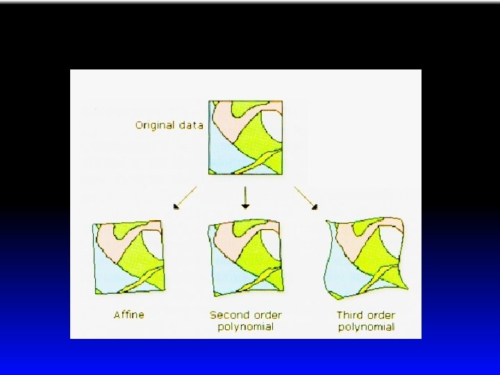
Raster coordinate systems Some raster data has a coordinate system predetermined; other do not have it established. If it has a coordinate system its GEOREFERENCED that means each pixel has an X, Y coordinate that corresponds to a location on the earth’s surface In cases where a coordinate system was developed but cannot be accessed by the software, you may need to look at the header of the data file (not easy or common), or look for an associated 6 line text file that describes the coordinates for georeferencing the raster In other cases you must provide ground control points to verify the precise location of places that can be identified on the image. Affine transformation is a first order translation that usually involves simple realignment of the X, Y coordinates Why bother? In some cases, the raster, if it is to be combined with other data sets (raster or Vector) may need to be aligned georeferenced before it can be transformed
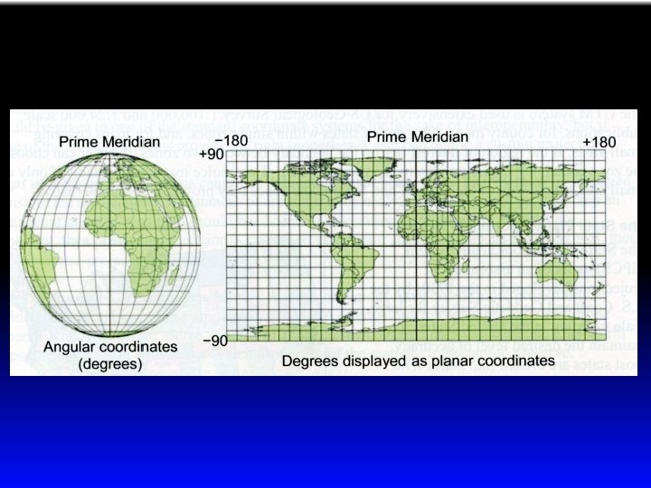
Common projection systems • A Geographic Coordinate System (GCS) – Not actually a projection, but commonly treated as one – Takes degrees (measured as arc or non planar distances) and treats them like equirectangular planar distances • This introduces some error, as lines of longitude converge and a 1° x 1° will not be either a square (except at the equator) or even a rectangle due to the convergence at the poles.
Universal Transverse Mercator (UTM) Based on Secant transverse cylindrical projection Divides up Earth’s surface into zones that are approximately 180 KM across (where the secant of the cylinder occurs as it intersects the globe’s surface.
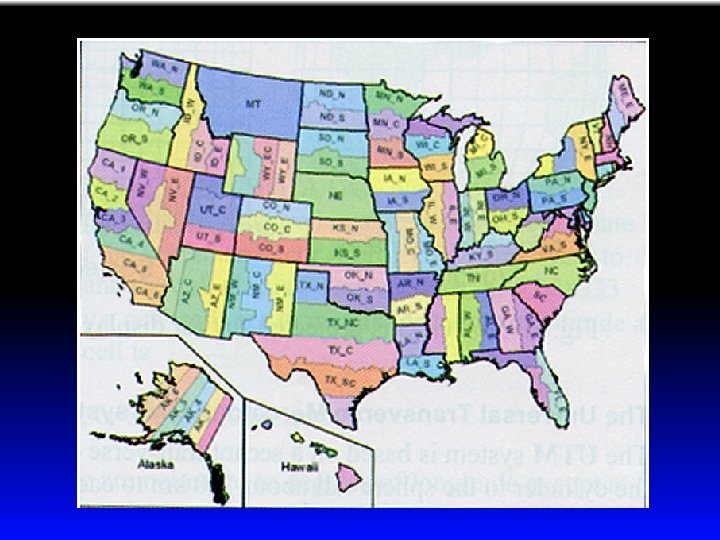
State plane coordinate system • Developed for large scale (small area) mapping of the US • Developed to minimize distortion within a state • Most states are split into at least two (and sometimes more ) zones, similar to zones within UTM • They can use different projections depending on the orientation of the state being projected and where it is located within the US – Lambert conformal conic – Transverse Mercator – Oblique Mercator