Chapter 3 Baseband Pulse and Digital Signaling Based

Chapter 3 Baseband Pulse and Digital Signaling

Based on the fundamentals learned in Chapters 12, we now consider specific communication issues. 1. 2. 3. 4. 5. Pulse code modulation and delta modulation N-ary digital signals Intersymbol interference Multiplexing Transmission

Basic Model of Communication Digital Source Transmitter Channel Receiver Destination Source generates from a finite set of symbols.

Transmitt er Source Encoder Channel Encoder Baseband Signaling • Source Encoder translates the out put of the source in an efficient manner for communication (e. g. , compression). • Channel Encoder transforms the coded source to enable error detection and correction at the receiver (e. g. , add redundancy). • Baseband signaling encodes digital information in a sequence of analog pulses.

Practical consideration of Channel Modulation Physical Transmission Physical Medium Physical Reception Demodulation Noise Channel model used in this class (simplified) H(f)

Receiver Optimal Filter Channel Decoder Source Decoder Optimal filter makes “best guess” of transmitted analog pulses. Channel decoder inverses operation of channel encoder (i. e. , error detection and correction). Source decoder inverses operation of source encoder.
 • Baseband operation • Transforming continuous time analog signals into")
Pulse Amplitude Modulation (PAM) • Baseband operation • Transforming continuous time analog signals into discrete time analog pulses • Information carried in amplitude of pulses. • First step in the analog to digital conversion (A/D) • Pre-cursor to Pulse Code Modulation (PCM) • Sometimes, PAM signals are used directly for transmission without making it into PCM • Two types of PAM – Gating – Sample and hold

Analog Source over Digital Communication Analog Source A/D Conversion Digital Communication System D/A Conversion Analog Output • PAM can be thought of as - Hybrid analog / digital communication system - Part of analog-to-digital conversion process
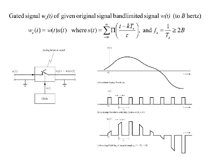
. Thus gated")
Any one of these has the same shape as the original W(f). Thus gated PAM is a linear operation.
 to the received PAM signal. This")
Demodulation of Gated PAM signal Oscillator multiplies cos(nwst) to the received PAM signal. This operation is equivalent to bringing down the frequency of received signal by nws.
. Thus S/H PAM")
They do not have the same shape as the original W(f). Thus S/H PAM is a non linear operation.
 is a special form of A/D conversion. It consists of")
Pulse Code Modulation (PCM) is a special form of A/D conversion. It consists of sampling, quantizing, and encoding steps. It is widely popular because: - Used for long time in telephone systems - Inexpensive electronics exists - Errors can be corrected during long haul transmission - Can use time division multiplexing PCM signal

Signals in PCM Process

Design Issues for PCM - Analog to Digital Conversion Aliasing Sample timing accuracy Quantization noise D/A accuracy Reconstruction filter - Digital Communication Technique Encoding and decoding Signal format Transmit and receive filters Channel effects Statistical decision making error
 is bandlimited to B hertz. Minimum sampling rate =")
Bandwidth of PCM Assume w(t) is bandlimited to B hertz. Minimum sampling rate = 2 B samples / second A/D output = n bits per sample (quantization level M=2 n) Assume a simple PCM without redundancy. Minimum channel bandwidth = bit rate /2 Bandwidth of PCM signals: BPCM n. B (with sinc functions as orthogonal basis) BPCM 2 n. B (with rectangular pulses as orthogonal basis) For any reasonable quantization level M, PCM requires much higher bandwidth than the original w(t).
 • Environment")
Effects of Noise Types of Noise • Quantizing noise (during A/D conversion) • Environment noise (e. g. , EM interference) • Filtering noise (low pass filtering at decoder) Types of Quantization Noise • Overload noise (input too large) • Random noise (input too small) • Granular noise (non uniform error jump) • Hunting noise (too long of quite time) Special quantizers are used (µ-law, A-law quantizers)
")
Performance of PCM (Pe 0, uniform quantization steps)

Quantization is a non linear transformation which maps elements from a continuous set to a finite set. It is also the second step required by A/D conversion. Analog Signal - Continuous time - Continuous value Sample Quantize - Discrete time - Continuous value Digital Signal - Discrete time - Discrete value
 -V V input w 1(t) -V Region of")
Uniform Quantization V output w 2(t) -V V input w 1(t) -V Region of operation For M=2 n levels, step size : = 2 V /2 n = V(2 -n+1)
 -V V input w 1(t) -V /2")
Quantization Error, e V output w 2(t) -V V input w 1(t) -V /2 - /2 Error, e input w 1(t)

Error is symmetric around zero. 0

Definition. The dynamic range of an input signal is the ratio of the largest to the smallest power levels which the input signal can take on and be reproduced with the acceptable signal distortion. The dynamic range of the quantizer input in the PCM system is 6 n d. B.

Nonuniform Quantizer Used to reduce quantization error and increase the dynamic range when input signal is not uniformly distributed over its allowed range of values. allowed values for most of time input time

“Compressing-and-expanding” is called “companding. ” Nonuniform quantizer Compressor Uniform Quantizer digital signals • • Discrete samples • • Channel received digital signals Decoder Expander output

Compression Techniques

Practical Implementation of µ-law compressor

Output SNR of 8 -bit PCM systems with and without companding.
 Channel H(f) w#(t) Optimal Filter •")
Baseband Signaling Transmit Receiver ter Baseband Signaling w(t) Channel H(f) w#(t) Optimal Filter • Once the sending end prepared digital signals (e. g. , PCM) to send, now it is the job of Baseband Signaling to prepare the signals suited for the channel. • What should w(t) be? Orthogonal set of signals { k (t), k=1, 2, 3, . . . , N}

Note • For practical implementation, we can only use a finite number, N, of the orthogonal set of signals { k (t), k=1, 2, 3, . . . , N}. • Again, for practical implementation, the time duration must be finite, To < . • The goal is to find a set { k (t), k=1, 2, 3, . . . , N} such that w(t) represents the digital signals prepared (e. g. , PCM) and a small amount of distortion in the channel does not affect the recovery of w(t) from the received signal, w#(t).
,")
Example. In ASCII character, “X” is 0001101. Then, using a certain { k (t), k=1, 2, 3, . . . , 7}, “X” is represented (for 0 < t < To) as
 rate D = N / To. Definition. Bit rate R =")
Definition. Baud (symbol) rate D = N / To. Definition. Bit rate R = n / To where n is the number of data bit sent in To seconds. If wk is binary, n = N and w(t) is a binary signal. If wk is not binary, n N and w(t) is a multilevel signal.

Binary Input 11 10 00 01 Output Voltage +3 +1 -1 -3

Example. 01 00 11 10 -3 -1 +3 +1 w 1 = -3, w 2 = -1, w 3 = +3, w 4 = +1 Note that 2 ms is allowed for sending each symbol.

Line Code • On the channel, we might want to send binary numbers directly. • The resulting bit patterns on the channel might create a static voltage, which is not desired. • Use line code to eliminate the average static voltage. - Save power - Save bandwidth (possibly) 1 5 volt 1 1 average static voltage 0 volt 0 0 0

Types of Line Code • Unipolar signaling: 1 = +A volt, 0 = 0 volt • Polar signaling: 1 = +A volt, 0 = -A volt • Biopolar signaling: 1 = +A or –A, 0 = 0 volt (Also called the alternate mark inversion – AMI) • Machester signaling: 1 = +A (half duration) followed by –A (half duration) 0 = -A (half duration) followed by +A (half duration) Additional combinations can be made along with RZ (return to zero) and NRZ (non return to zero).


Desired Properties of Line Code • Self synchronization • Low probability of bit error • Spectral efficiency • Low transmission speed • Error detection capability • Transparency

Power Spectral Density for Line Code (We will not follow the details in the book. )

Eye Pattern Seen in oscilloscope The Cleaner, the better Good indication of transmission quality

Regenerative Repeater

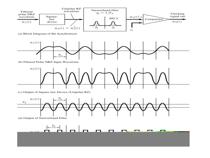
Bit Synchronization To accurately detect received signals, synchronization timing is needed. - derived from received data - separate signal sent from source Synchronization - bit level - frame level - carrier level

Binary-to-Multilevel Conversion

Spectral Efficiency Line Code Unipolar NRZ Polar NRZ Unipolar RZ Bipolar RZ Manchester NRZ Multilevel polar NRZ First Null Bandwidth (Hz) R R 2 R R/l Spectral Efficiency =R/B bits/s 1 1 0. 5 l

Intersymbol Interference • No channel has infinite bandwidth • Most transmission schemes require higher bandwidth than available in the channel. - Square wave requires infinite bandwidth. - Synch function is not possible due to causality violation. - Modified synch function to satisfy the causality requires higher bandwidth. • Each symbol may be smeared into adjacent time slots. • Intersymbol Interference (ISI) is the spreading of symbol pulses from one slot into adjacent slots.

Baseband Pulse-Transmission System
? Nyquist’s First Method (Zero ISI)")
Finding He(f)? Nyquist’s First Method (Zero ISI)
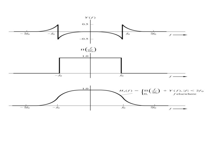
? Raised Cosine-Rolloff Nyquist Filtering")
Finding He(f)? Raised Cosine-Rolloff Nyquist Filtering


Raised Cosine-Rolloff Filter as Nyquist Filter.
 1 f -2 fo -fo fo 2 fo")
Other Nyquist Filters H(f) 1 f -2 fo -fo fo 2 fo

 HT(f) HC(f) HR(f) channel characteristics is unknown. Equalization:")
How are Nyquist filters realized? H(f) HT(f) HC(f) HR(f) channel characteristics is unknown. Equalization: HR(f) is an adaptive filter. tune HR(f) till match is achieved H(f) HT(f) HC(f) HR(f) input test sequence Desired He(f) specify desire characteristics + + compare -

Pulse - Often. Differential voice and video signals. Code do not Modulation change much from one sample to next. (DPCM) - Such signals has energy concentrated in lower frequency. - Sampling faster than necessary generates redundant information. Can save bandwidth by not sending all samples. * Send true samples occasionally. * In between, send only change from previous value. * Change values can be sent using a fewer number of bits than true samples. Examples (CCITT standards) * 32 k bits / s (4 -bit quantization and 8 k samples /s) for 3. 2 k. Hz * 64 k bits / s (4 -bit quantization and 16 k samples /s) for 7 k. Hz
")
For slowly varying signals, a future sample can predicted from past samples. + s(t) Predictor Transmitter Side + - e(t) + + s(t) + Predictor Receiver Side Transversal filter can perform the prediction process.

One Implementation of DPCM Quantization error is accumulated.

Another Implementation of DPCM Quantization error is not accumulated.
 - Special type of DPCM with M = 2. Inexpensive and")
Delta Modulation (DM) - Special type of DPCM with M = 2. Inexpensive and simple to implement.

DM Waveform
")
Some notes about DM Bit rate = sampling rate Reconstructed signal where y(i. Ts) = +1 or -1 and is the step size. Types of noise * Quantization noise: step size takes place of smallest quantization level. * Granular noise: z(n. Ts) is always different from z((n-1)Ts). * Slope overload noise: maximum slope of output signal is / Ts.

too small: slope overload noise too large: quantization noise and granular noise There is an optimum value for in terms of signal bandwidth, signal power, and sampling frequency.

Adaptive Delta Modulation Inappropriate step size creates noise. Make adaptive. number of successive 1’s or 0’s size 1 2 3 4. step 2 4 .

ADM Block Diagram.

Speech Coding - Waveform coders: output approximates original voice signal. * PCM, DM, CVSD (24 – 64 k bits/s) - Vocoder: parameterize voice signals based on speech models * CELP, VSELP (2 -16 k bits/s)

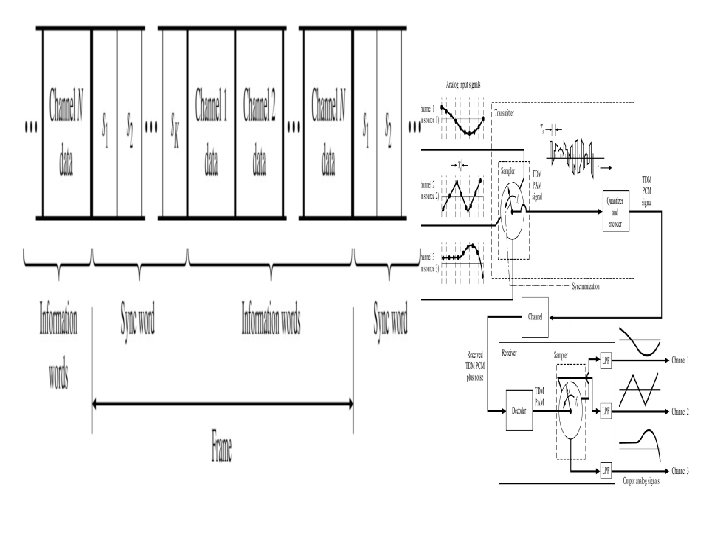
Time Division Multiplexing • Time interleaving of samples from different sources to be transmitted over a single communication channel.

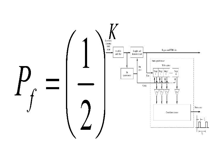
Frame Synchronization • Framing is done to delimit the boundaries of data units. (e. g. , 24 PCM samples collected from 24 difference sources, each corresponding to a voice sample) • The receiver sees a continuous stream of symbols (for binary signals, 1’s and 0’s). • How does the receiver know, for example, where the different PCM samples are? Certain unique string of bits is used to indicate the boundaries of frames. • The channel data may contain the bit patterns that happen to be identical to the framing bit string. Certain bit stuffing and de-stuffing methods are necessary to avoid such situations. • Probability of any arbitrary bit string matching a K bit framing string:

Frame Synchronizer

North American TDM Hierarchy.
")
T 1 TDM Format for One Frame. (8000 samples / s)
- Slides: 74