Chapter 27 Ignition Systems Primary Circuit Components Battery

Chapter 27 Ignition Systems
 Ignition")
Primary Circuit Components • • • Battery Ignition switch Ballast resistor (older systems) Ignition coil primary winding Triggering device Switching device or control module

Primary Circuit Operation • Ignition switch on. • Current flows into primary coil winding. • A primary switching device stops current flow through the coil. • This causes the magnetic field to collapse.
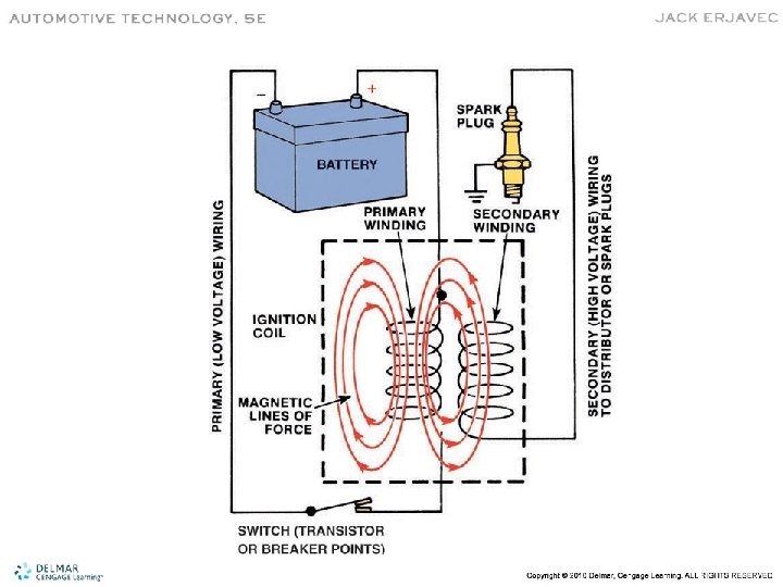

Secondary Circuit Components • • Ignition coil secondary winding Distributor cap and rotor (DI systems) Spark plug cables (some systems) Spark plugs

Secondary Circuit Operation • Collapse of the magnetic field in the primary induces high voltage into the coil secondary. • This voltage is used to establish a complete circuit so current can flow. • The excess energy is used to maintain the current flow across the spark plug gap.

EI Systems • May have a single coil for each cylinder or two cylinders may share a coil. • The ignition module controls firing order and spark timing. • Additional energy is released as current flow. • This allows higher firing current and longer firing times, 1. 5 ms compared to DI’s 1 ms.

Ignition Coils • Coils are pulse transformers. • Output dependant upon the number of windings and current flow. • CEMF increases time to become fully saturated. • Dwell is the period of current flow.

Secondary Voltage • Typical voltage requirement to jump the plug gap is 10, 000 volts. • Most coils have at least 25, 000 volts available – called secondary reserve voltage. • Reserve necessary to compensate for high cylinder pressures.

Spark Plugs • Provides the air gap. • Resistor reduces RFI. • Standard plug electrodes are copper. • Platinum and iridium electrodes extend plug life.

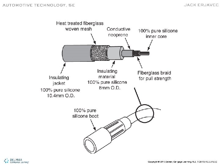
Ignition Cables • • Carry high voltage to spark plugs. Carbon fiber core acts as a resistor. Reduces RFI and increases firing voltage. Reduces plug wear by reducing current.

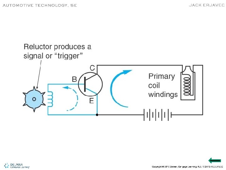
Triggering and Switching Devices • A triggering device monitors crankshaft position. • A switching device controls current flow through the coil primary winding. • Electronic switching components are part of an ignition control module or the PCM.

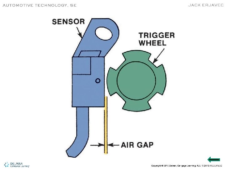
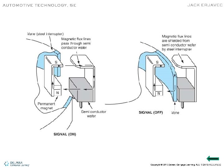
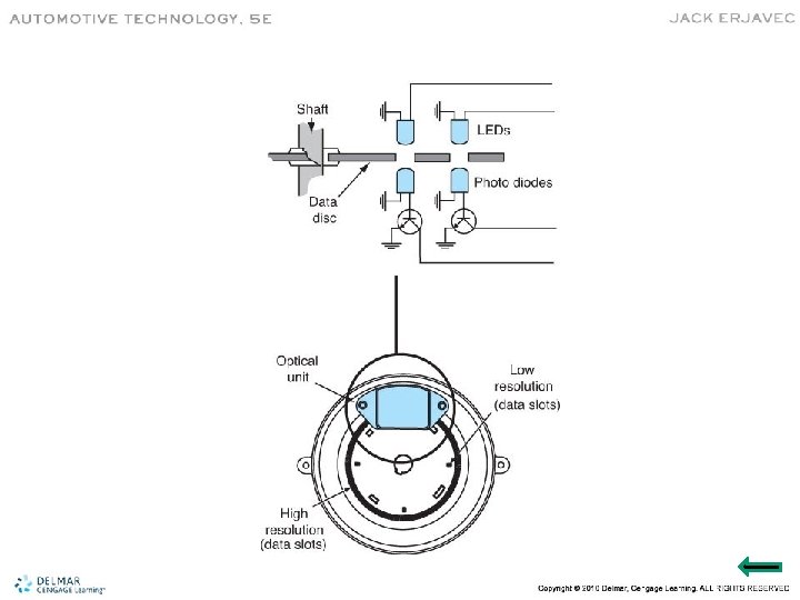
Engine Position Sensors • Magnetic Pulse Generator – Consists of a reluctor and pickup coil • Metal Detection Sensor – The electromagnet is in the pickup coil • Hall-effect Sensor – Produces a square wave signal – Is most commonly used • Photoelectric Sensor – Uses an LED and moving slotted disc

Timing Retard and Advance • Timing controlled by ignition module. • Older systems used mechanical and vacuum systems.

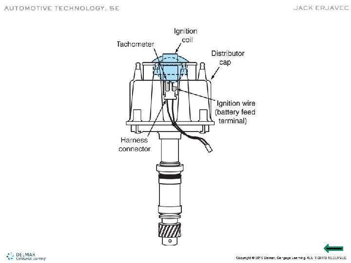
Distributor • May contain pick up assembly, ignition module, and coil. • Shaft driven by camshaft. • Rotor sits on top of distributor shaft and spins inside of distributor cap. • A typical distributor.

Electronic Ignition Systems • • • No moving parts. Cylinders individually controlled. Flexible mounting locations. Less radio frequency interference. No timing adjustments. More time for coil saturation.

Double-Ended Coil or Waste Spark Systems • One coil fires two plugs. • These are the companion cylinders. • One plug fires positive to negative • The other fires negative to positive

Coil-Per-Cylinder Ignition • Coil-on-plug and coil-near-plug • Allows for more time between firings and increased saturation time. • A single coil failure affects only one cylinder. • COP require adaptors or plug wires to connect an ignition scope.

EI System Operation • Biggest differences are in number of coils and the use of CKT and CMP sensors. • Layout and operation of the sensors are designed to provide fast engine starts and synchronization of the fuel and ignition systems.

Hall-Effect Sensors

Magnetic Pulse Generators

Misfire Detection • The CKP identifies which cylinder. • Detected by variation in crank speed. • PCM uses wheel speed data to determine if crank speed variation is from rough road conditions or misfire.

Basic Timing • The PCM controls timing and is not adjustable. • Timing is fixed during cranking. • Once a certain engine speed is reached, the PCM adjusts timing. • Timing inputs include RPM, load, throttle position, and coolant temperature.

Timing Corrections • Temperature – Advanced with low coolant temperature • Engine Knock – Timing retarded when knock is detected • Stabilizing Idle – Used if desired idle speed is not correct

Coil Cross-Section

• Platinum tipped spark plug

Vacuum advance
- Slides: 33