Chapter 25 Engine Performance Systems Engine Performance Systems


 • • Basic data parameters and codes. Monitors effectiveness of emissions")
 • Standardized • Vehicles may have more than one DLC.")


 • Tests the ability of the fuel tank to")

 System Monitor • Can be tested by injecting air upstream")
 • Continuous monitor. • Looks at any electronic input that")


 • Mode 2 – freeze frame data access mode • Mode")
 • Mode 6 – hexadecimal data – Can be used for")


 • • • Check DTCs and monitors. Basic inspection. DTC")


 occur at")
- Slides: 55
Chapter 25 Engine Performance Systems
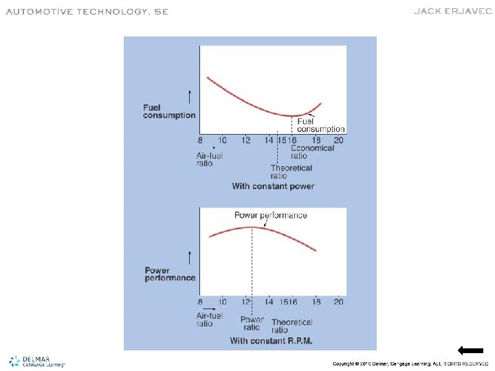
Engine Performance Systems • Responsible for how the engine runs. • Complete combustion requires: – Correct amount of air – Correct amount of fuel – Mixed in a sealed container – Shocked with the correct amount of heat
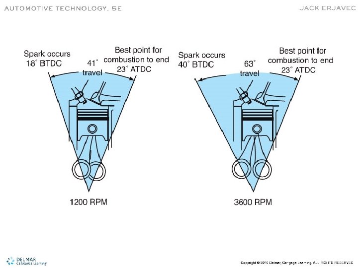
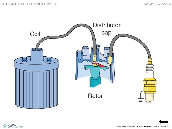
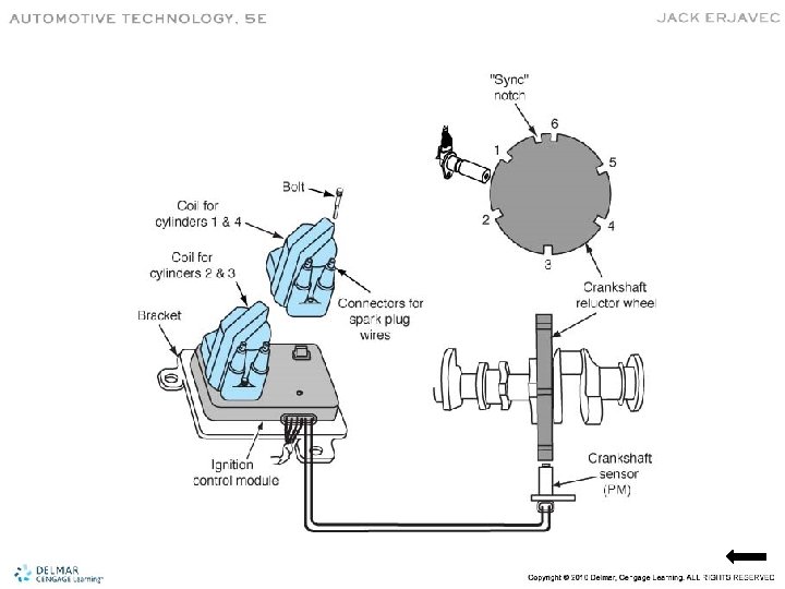
Purpose of the Ignition System • Generate enough heat to ignite mixture. • Maintain the spark long enough for total combustion of the fuel. • Must deliver the spark to each cylinder to allow combustion to begin at the correct time.
Firing Order • To supply spark at the correct time, each cylinder fires in a specific order every 720 degrees.
Fuel Systems • Typical fuel supply system includes: – Fuel tank, lines, filter, and a pump • A pressure regulator maintains system pressure. • The pressure generates the spraying force to inject the fuel.
Fuel Injection - TBI
Fuel Injection - CPI
Fuel Injection - PFI
Fuel Injection - GDI
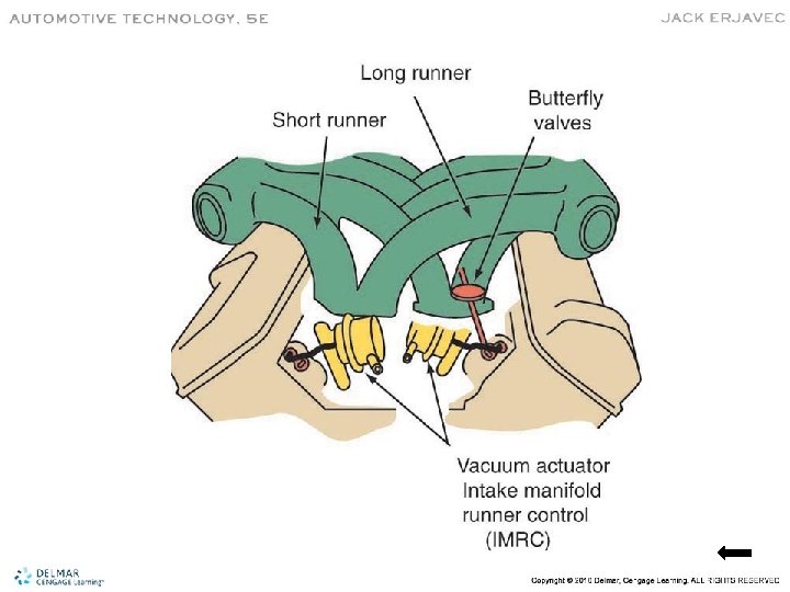
Air Induction System
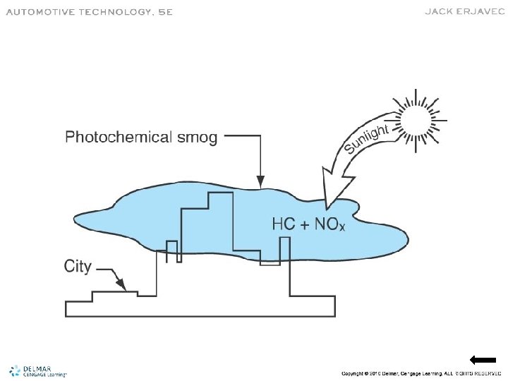
Emission Control Systems • Reduce pollutants and environmentally damaging substances. • Smog irritates eyes, nose, and throat. • Formed when HC and NOx are exposed to sunlight.
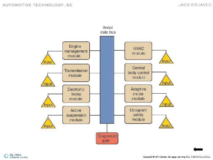
Engine Control Systems • Primary engine control computer is the ECM or PCM. • Based on input, may command a change. • Monitors system activity for faults. • Linked to several other modules. • Share information on the CAN data bus.
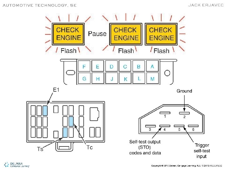
On-Board Diagnostic Systems • OBD I – Phased in 1988 – Most used flash codes – DTC represented open, shorted, high resistance, or outside normal range faults – Monitored a few systems and had limited DTCs – Often required a specific scan tool
OBD II • Designed to ensure emissions remain as low as possible over life of vehicle. • Added monitor functions: – Catalyst efficiency – Engine misfire – Evaporative system – Secondary air system – EGR flow rate
OBD II (cont’d) • • Basic data parameters and codes. Monitors effectiveness of emissions system. Every part that affects emissions is checked. MIL illuminated if emissions exceed 150% of allowable standard for that vehicle. • PCM uses EEPROM for updates.
Data Link Connector (DLC) • Standardized • Vehicles may have more than one DLC. • Must be located near steering column.
System Operation • Closed Loop Mode – PCM receives and processes information and adjusts outputs, resulting in new input data • Open Loop Mode – Used when the engine is cold – PCM does not respond to feedback information – Makes decisions based on programming
OBD II Monitoring Capabilities • • • Monitors to detect failing systems. Illuminates the MIL before the failure. Performs tests on subsystems. Some monitors run continuously. Other monitors only run under certain operating conditions, called enable criteria.
OBD II Trip
Catalyst Efficiency Monitor • Uses two oxygen sensors. • Converter stores oxygen when lean. • Efficiency is measured by oxygen storage.
Misfire Monitor • Unburned fuel enters exhaust. • Can destroy catalyst. • Uses CKS sensor. • Most OBD II systems allow about 2% rate.
Type A Misfires • • • Checked for at 200 -rpm increments. A misfire between 2% and 20% is excessive. PCM may shut off fuel injector(s). If injector(s) not shut off, the MIL flashes. If injector(s) are shut off, the MIL illuminates.
Type B Misfires • Checked over a 1000 -rpm period. • If misfire exceeds 2% to 3%, it is considered excessive. • May not damage catalyst but will increase emissions. • A pending DCT set. • MIL on if fault detected on second trip.
Fuel System Monitoring • The PCM monitors and adjusts fuel delivery based on oxygen sensors feedback. • Short term fuel trim (STFT) makes minor injector pulse-width adjustments. • Long term fuel trim (LTFT) is set by the effectiveness of STFT. • The fuel trim monitor is continuous.
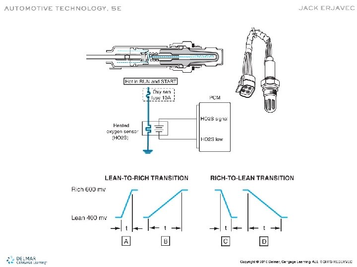
Heated Oxygen Sensor Monitor • Rich to lean and lean to rich response times. • Report time of sensors gives an indication of heater circuit operation. • All HO 2 S monitored once per drive cycle. • The monitor will vary fuel delivery to check HO 2 S response.
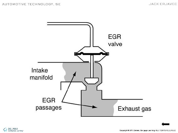
EGR System Monitoring • Some systems monitor EGR temperature. • Other systems use the MAP sensor data. • Monitors EGR operation, flow rates, and opens and shorts in the circuit.
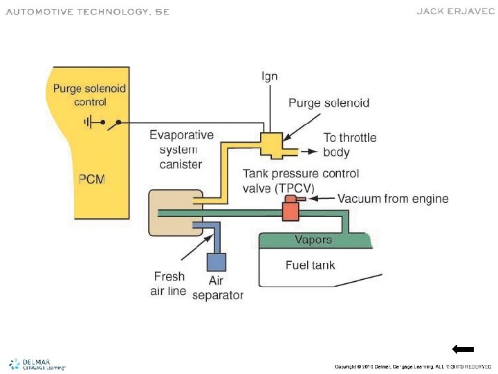
Evaporative Emission System Monitor (EVAP) • Tests the ability of the fuel tank to hold pressure. • Also tests the systems ability to purge fumes from the charcoal canister.
Enhanced EVAP Systems • • • In use since 2003. Detects leaks and restrictions. Checks EVAP system integrity. Performs a vacuum test. Uses a special fuel filler cap. Loose or missing filler cap will set an EVAP code.
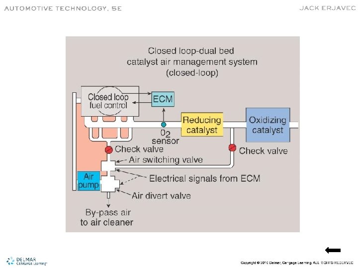
Secondary Air Injection (AIR) System Monitor • Can be tested by injecting air upstream of HO 2 S sensor. • Many systems inject air into exhaust manifold during open loop. • Air then injected into catalytic converter during closed loop.
Comprehensive Component Monitor (CCM) • Continuous monitor. • Looks at any electronic input that could affect emissions. • Monitors sensor range values. • Checks frequency input rationality. • Monitors outputs by checking voltage.
MIL • Must illuminate if an emissions fault is detected. • MIL may stay on or blink. • MIL may go back off but a DTC and freeze frame are stored. • If the fault is not detected for 40 key cycles, the DTC and freeze frame are erased.
OBD II Trouble Codes • DTCs are standardized
Freeze Frame Data • PCM takes a snapshot of activity when the MIL is illuminated. • Used by PCM for comparison of operating conditions if the same problem reoccurs. • Can be useful by technicians. • Erased if the DTC is erased.
Test Modes • All OBD II systems have same basic test modes accessible with an OBD II scan tool. • Mode 1 – parameter ID (PID) mode – Allows access to current data values, calculated values, and system status information – Some PID values are manufacturer specific
Test Modes (cont’d) • Mode 2 – freeze frame data access mode • Mode 3 – access to stored DTCs • Mode 4 – PCM reset mode – Resets all DTCs, freeze frames, DTC histories, monitor test results, and monitor status • Mode 5 – O 2 sensor monitoring test – Actual O 2 sensor outputs during test cycle – Used for catalyst efficiency monitoring
Test Modes (cont’d) • Mode 6 – hexadecimal data – Can be used for non-continuous system problem identification • Mode 7 – test results for continuous monitoring systems • Mode 8 – bidirectional control request • Mode 9 – vehicle information request
Repair Information • • DTC and freeze frame retrieval No communication diagnosis TSBs Strategy chart for DTCs Parts locations Wiring diagrams Component test sequences
Troubleshooting OBD II Systems • • Interview the customer. Check the MIL. Connect scan tool. Check DTCs and freeze frames. Check service history and information. Record data and clear DTCs. Visual inspection.
Troubleshooting OBD II (cont’d) • • • Check DTCs and monitors. Basic inspection. DTC chart. Check for intermittent problems. Perform repairs. Repair verification.
Intermittent Faults • • May not set DTC or light the MIL. Check history DTCs. Evaluate symptoms and conditions. Identify circuit or system that may be at fault. Follow intermittent procedures in manual. Visual inspection. Test circuit wiring.
Serial Data • PIDs are codes used to request data from PCM. • Scan tools request and receive serial data. • Scan tool PID requests information from a device on the network. • Many PIDs are standard but not all are supported by all manufacturers.
Diagnosing OBD I Systems • Limited self-diagnostic capability. • Hard faults (on-demand) occur at time of self-test. • Intermittent faults not present at self-test can store a DTC for a number of key cycles. • Several different methods to access DTCs. • Perform a thorough visual inspection.