Chapter 25 Elevation Layout and Drawing Techniques Introduction


 • Refer to the text for complete instructions – Overall-shape layout")

 • Procedures: – Darken lines at the top")


- Slides: 22
Chapter 25 Elevation Layout and Drawing Techniques
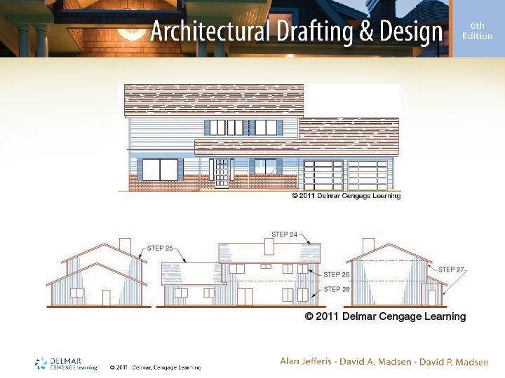
Introduction • Elevations – Architect or job captain draws main elevations in preliminary design stage – Senior drafter finishes them – Beginners may be introduced to elevations by making design change corrections – Drawn in three steps: layout, drawing, and lettering
Layout • Elevations drawn using Auto. CAD – Can be full-size – May be aligned beside each other • Elevations drawn manually – Drawing sheet size will affect scale, placement, and layout • C-sized sheet is commonly used
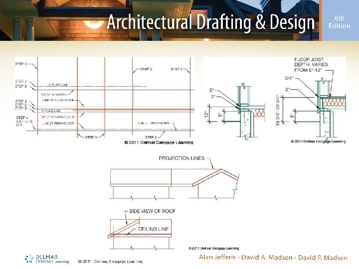
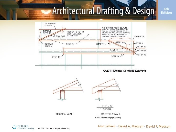
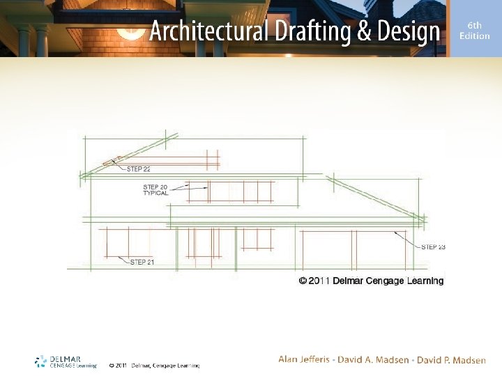
Layout (cont’d. ) • Refer to the text for complete instructions – Overall-shape layout – Roof layout – Layout of openings
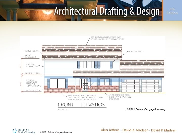
Drawing Finished-Quality Lines Manually • Elevations, drawn with construction lines, are completed with finished-quality lines – H and 2 H leads provide good contrast – Ink and graphite produce nice effects – Varied line width and density produce more realistic elevations
Drawing Finished-Quality Lines Manually (cont’d. ) • Procedures: – Darken lines at the top of the page first and work down • Use a soft lead – Start at the top of one elevation and work toward ground level – Start by drawing surfaces in the foreground and work toward the background
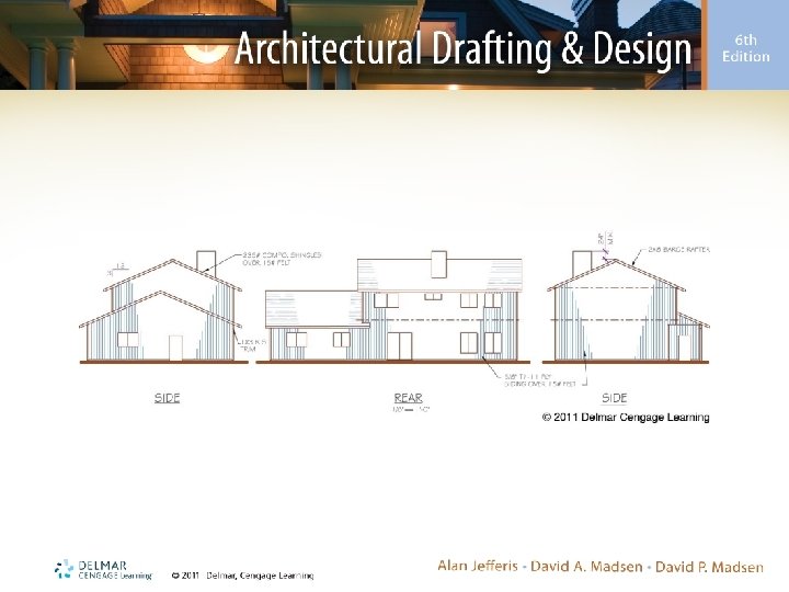
Annotation • Required notes include: – Siding – Corner and decorative trims – Chimney height and flatwork – Posts and headers – Fascias and barge rafters – Roof material and pitch – Dimensions
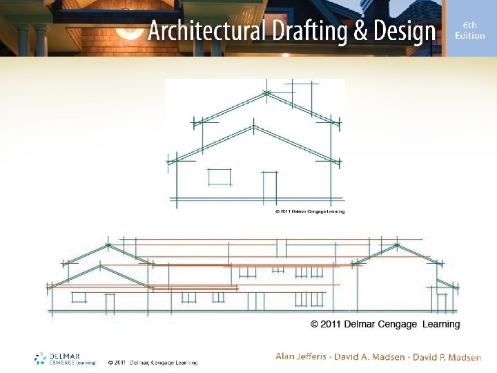
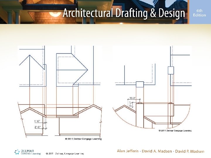
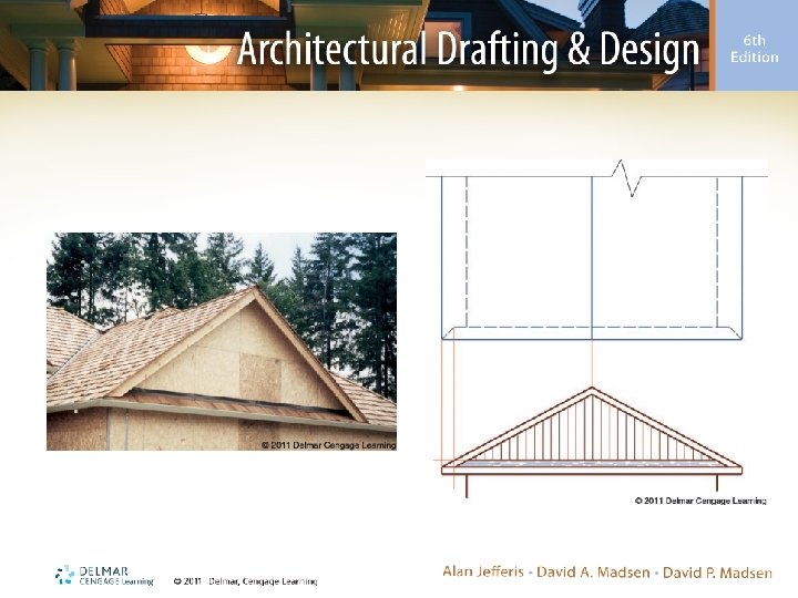
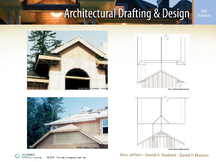
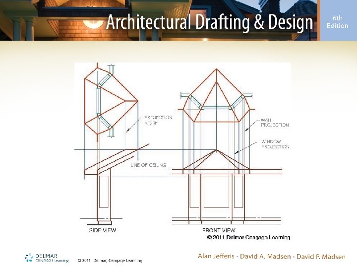
Drawing Roof Intersections • Roof shape can be projected from: – Roof plan – Overlay of the roof placed on floor plan
Drawing Irregular Shapes • Not all plans have walls constructed 90° to each other – A floor plan and roof plan are required to draw elevations for a house with an irregular shape
Projecting Grades • Grade describes the finish ground shape – Projecting ground levels is required if a structure is constructed on a hillside
Elevation Checklist • An elevation checklist includes: – Drawing setup – Drawing – Specifications – Dimensions • Refer to the text for a complete checklist