Chapter 2 Strowger Switching Systems Automatic Switching System


- Slides: 30
Chapter 2 Strowger Switching Systems
Automatic Switching System Advantages:
Rotary Dial Telephone �A formal numbering plan or addressing scheme is required to identify the subscribers. � A mechanism to transmit the identity of the called subscriber to the exchange now required at the telephone set. � Two methods for this purpose: i) Pulse dialing ii) Multi frequency dialing
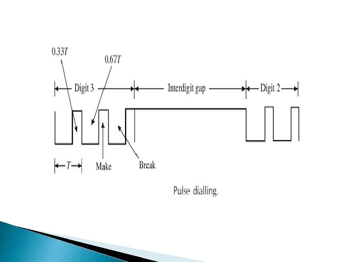
Pulse Dialing
The following points have to be considered for the telephone set: � Since the pulses are produced by make and break of the subscriber loop, there is likelihood of sparking inside the telephone instrument. � The transmitter, receiver and the bell circuits of the telephone set may be damaged if the dialing pulses are passed through them. � The dialing habits of the users vary widely and hence all timing aspects should be independent of user action.
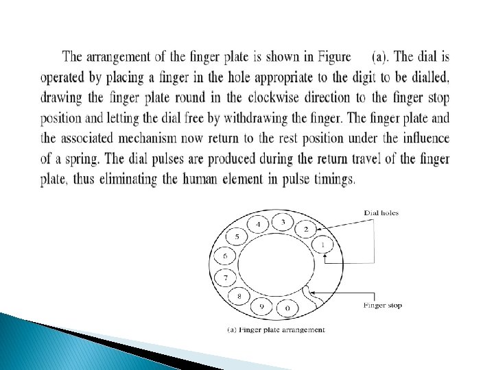
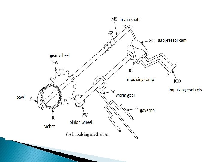
Rotary Dial Telephone
Parts and Mechanisn:
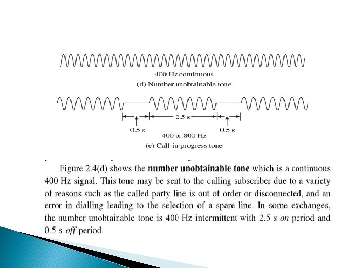
Signaling Tones:
Strowger Switching Components:
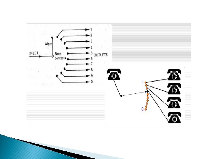
Uniselector
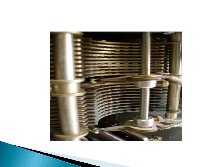
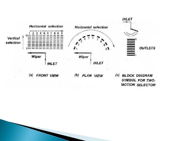
Two Motion Selectors
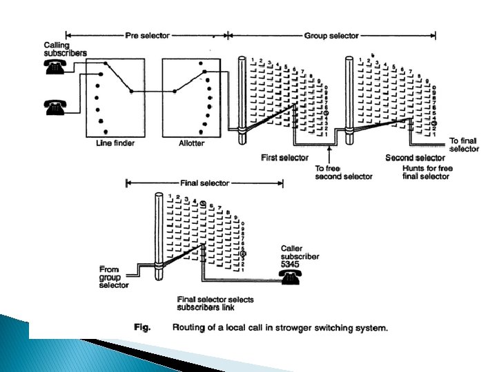
Step-by-Step Switching System
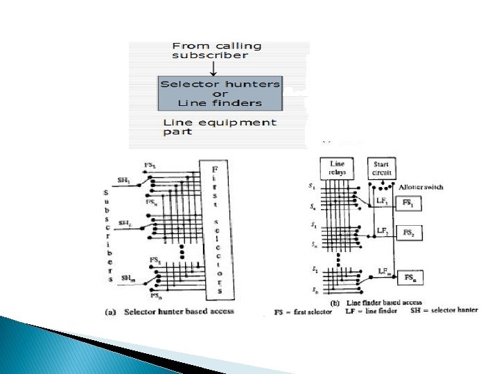
Selector Hunter Based Access To find a free selector, alloter switch is used for connecting calling subscriber and selector line, selector hunter based access or line finder based access can be used. In selector hunter based access, when a subscriber lifts his handset, the interrupter mechanism in his selector hunter gets activated and the wiper steps to find free first selector. Once the free first selector is sensed, it is marked busy and the interrupter mechanism of selector hunter is disabled. Now the first selector sends the dial tone to the subscriber and then ready to receive dialled pulses from the calling subscriber. Thereafter, the first selector provides only electrical paths between calling subscriber and group selector.
Line Finder Based Access In line finder based access approach, the seize is identified by interupt mechanism. Through the alloter switch, free line finder is identified. It gets activated and its wiper steps forward to reach the subscriber contact. Now the corresponding first selector sends the accept signal as dial tone. Thereafter, it acts as a simple electrical path between calling subscriber and group selector.
Call Set-up
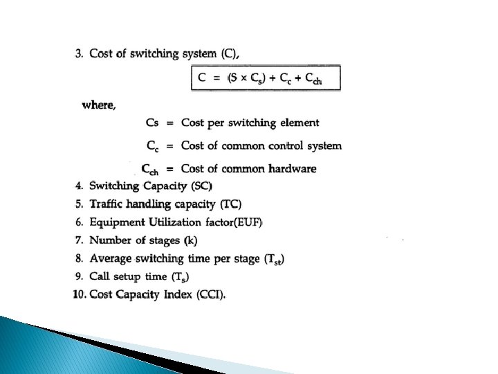
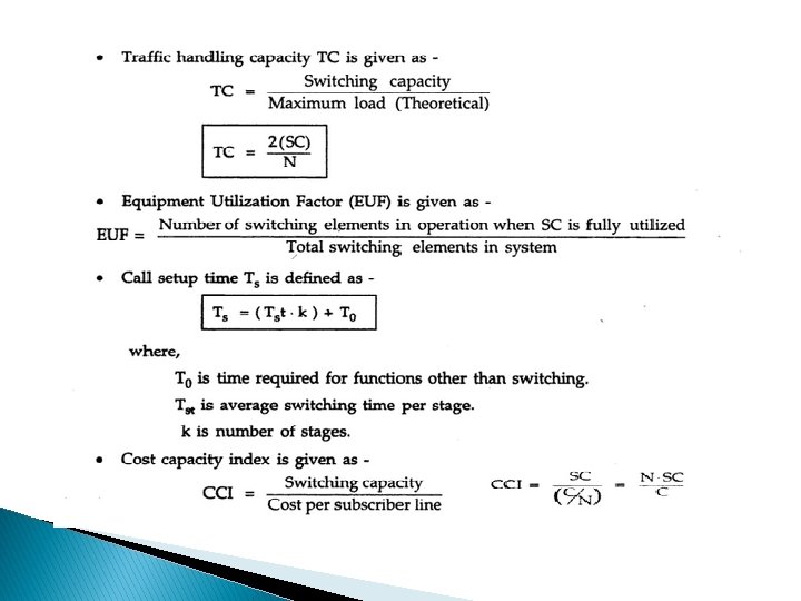
Design Parameters
100 -line Switching System
� Total Number of Switching Elements, S=110 � Switching Capacity, SC=10 � Number of Switching stages, K=2 � � TC=(switching capacity)/(theoretical maximum load) =(2 SC)/N =0. 2 EUF=(number of switching elements in operation when SC is fully utilized)/(total number of switching elements in the system) =0. 18 � C=110 � CCI=9. 09
Assignment � Design 2, Design 3, Design 4 and Design 5 for 100 line switching system. � 1000 line Blocking Exchange.