Chapter 2 Storage Devices and Interfacing Visit for


 Disk platters")
 �The platters stores information. It comes in varying sizes like 5.")


 Structure Partition Boot Sector Master File Table System File")


- Slides: 25
Chapter 2 : Storage Devices and Interfacing Visit for more Learning Resources
Recording Techniques : 1. FM encoding method 2. MFM encoding method 3. RLL encoding method
1. FM Encoding Scheme: • This method of data encoding is also known as the “Single density recording”. • In this FM method of data recording a 1 bit is stored as two pulses(one clock pulse and one data pulse), and a 0 bit is stored as a one pulse and one gap or no pulse. • For example, a binary number 1011 will be stored as PP PN PP PP
2. MFM Encoding Scheme: • More data can be stored on the same surface or the data storage density can be increased, if the number of pulses required to store the data can be minimized. • • In MFM recording the 0 s and 1 s are encoded as given below • 1 is always stored as no pulse, and a pulse(NP) • 0, when preceded by another 0, is stored as a pulse, and no pulse(PN) • 0, when preceded by a 1, is stored as two no pulses(NN)
• If you store 1001 on the disk surface using the MFM storage method, it would be stored as NP NN PN NP.
3. RLL Encoding Scheme • The RLL is encoding or the run length limited encoding is the most common encoding scheme used in the hard disk storage. • The RLL encoding scheme can store 50 percent more information than MFM encoding scheme on a given surface and it can store three times as much information as the FM encoding scheme. The Run length Limited name comes from the minimum number (run Length) and maximum number (run Limit) of “no pulse” values allowed between two pulses. • For the RLL encoding, an encoder/decoder (Endec) table is used to find the pulse signal to be used for different data bit groups. Endec table used by the IBM to convert bit information to the pulse signal is shown below
Data Bit 10 11 000 011 0010 0011 Pulse Encoding NPNN PNNN NNNPNN PNNPNNPNN NNNNPNNN • For example, if you want to encode a byte 100011 to proper RLL pulse signal then the • Bit 10 can be encoded as NPNN • Bit 0011 can be encoded as NNNNPNNN
Perpendicular Encoding : • Virtually all hard drives record data using longitudinal recording which stores magnetic bits horizontally across the surface of the media. • However perpendicular recording which aligns magnetic signals vertically on the media surface has the potential to achieve higher data intensities because vertically oriented magnetic bits use less space than longitudinally stored bits.
Hard Disk Construction :
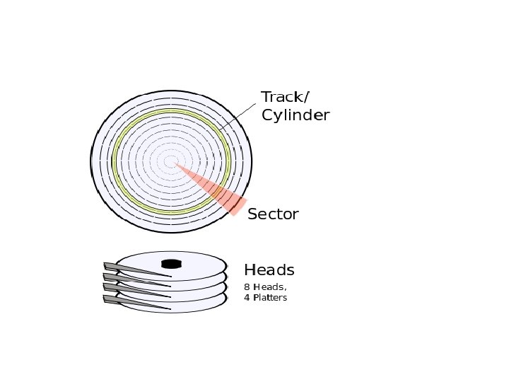
A hard disk drive is made up of several physical components 1) Disk platters 2) Read/write heads 3) Head actuator mechanism 4) Spindle motor 5) Logic board 6) Cables and connectors 7) Bezel / Front Plate 8) Air Filter 9) Head Arm/head slider
Hard Disk Platters(Disks) �The platters stores information. It comes in varying sizes like 5. 12”, 3. 14”, 0. 85” etc. The physical size of a drive is expressed as the size of the platters �Most hard disk have two or more platters �Platters were originally made from an aluminium/magnesium alloy which provides bothe strangth and light weight �All modern drives use glass or glass ceramic plates. Read/Write Heads �A hard disk drive usually has one read/write head for each platter surface(meaning that each platter has two sets of read/write heads-oneee for top side and one for bottom side �These heads are connected on a single movement mechanism so heads across the platters in unison. �The HDD uses various types of heads for read/write purpose. �Ferrite head �Metal-In-Gap Head, Thin Film Head �Magneto Resistive Head �Giant Magneto Resistive Head
Head Actuator Mechanism �This mechanism moves the heads across the disk and positions them accurately above the desired cylinder. �Two basic Categories are used �Stepper Motor Mechanism �Voice Coil Actuator �Stepper Motor actuators were commonly used on hard drives made during the 1980 s and early 1990 s with capacities of 100 MB or less �Floppy disk drives position their head by using a stepper motor actuator �All hard disk drives being manufactures today use voice coil actuator. Voice Coil Actuator The two main types of voice coil positioner mechanisms are Linear Voice Coil Actuators Rotary Voice Actuators
Spindle Motor �The spindle motor spins the platters connected to spindle. The motor is directly connected to the spindle of platters. These platters revolve at exactly 3600 rpm to 1500 rpm. The speed of motor has to be controlled very precisely. �Normally a feedback loop is employed in the control electronics to monitor the speed. The speed control is fully automatic. Logic Boards - A disk drive will have a board containing the electronics that control the drive’s spindle and headactuator systems These are calledlogic boards. - They present data to the controller in aplanned format. - They may be removed and replaced to rectify a logic board problem. Cable and Connectors �Cable and connectors are used to connect HDD to the main computer system. �All hard disj drive contains connections for Data/Control interface connector, Power connector
Bezel/ Front Faceplate Bezel is the front faceplate provided on most of the hard disk drives. Air Filters �Nearly all hard disk drives have two air filter. One is called the recirculating filter and the other is called either a barometric or breather filter. �These filters are permanently sealed inside the drive and are designed never to be changes for the life of the drive. �A hard disk on a PC system does not circulate air from inside to outside the HDD or vice versa. �The recircualting filter permanently installed inside HDA is designed to filter only small particles. Scraped off platters during head takeoffs and landings.
Terms Related to Harddisk : 1. Track 2. Sector 3. Cylinder 4. Cluster 5. Landing zone 6. MBR 7. Zone Recording 8. Write Precompensation 9. Interleave and Interleave factor Cluster When OS writes some information on the hard disk, it does not allocate the space sector wise, instead uses a new unit of storage called “Cluster” Clusters are the minimum space allocated by DOS when storing any information on the disk Even to store only one byte long information on the disk requires minimum one cluster area on the disk surface A cluster can be made up of one or more sectors, it depends on disk type being used. This reduces the size of FAT that DOS uses to keep track of the used and the empty disk space First cluster no. is taken as 2 Clusters are used to allocate the storage area for data area only, FAT and directory areas are not allocated according to the cluster size
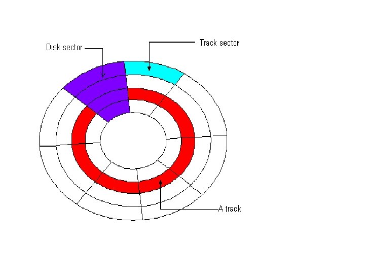
Cylinder Same tracks of different platters form an imaginary cylinder like structure Data is stored cylinder by cylinder All tracks on a cylinder are written and then the R/W head moves to the next cylinder. This reduces movement of R/W head and increases the speed of read and write operation Sector A track is a big area to store data( 5000 bytes). Hence tracks are divided into sectors The formatting program divides disk surface into sectors by writing magnetic pattern on disk surface Different HDD capacities have different number of tracks 512 byte data can be stored in each sector. Sector no. starts from 1
Landing zone: This setting specifies the cylinder to which the BIOS should send the heads of the hard disk when the machine is to be turned off. This is where the heads will "land" when they spin down. Modern drives automatically park the heads in a special area that contains no data when the power is turned off. Therefore this setting is meaningless and is typically ignored. Most BIOSes set this value to be the largest cylinder number of the logical geometry specified for the disk when auto detection takes place. So if the drive has 6, 136 logical cylinders, the landing zone will be set to 6, 135. In any event a modern IDE drive will ignore this setting and auto-park by itself. Zone Recording One way to increase the capacity of a hard drive during the low level format is to create more sectors on the disks Outer cylinders than on the inner ones. Because they have a larger circumference the outer cylinders can hold more data. Drives that use zoned recording split the cylinders into groups called zones, with each successive zone having more sectors per track as you move outward from the center of disk.
Write Pre-compensation It is useful for drives using standard track, sector format Drives using zone bit recording do not require any write pre- compensation The magnetic particles used to write on the disk surface have north and south poles Like poles repel and unlike poles attract In outer surface of hard disk platter, magnetic particles are far apart to be affected by the attraction and repulsion of magnetic particles In the inner tracks of the disk drive, the density of the magnetic are very high and adjacent particles start to attract and repel. This will force to change the information written on the disk To compensate for this shift of data particles due to attraction and repulsion, the drive can write the data apart or closer than the required position Master Boot Record (MBR) : Short for Master Boot Record, a small program that is executed when a computer boots up. The MBR contains two elements; 1. executable code and 2. a partition table,
TRACKS: Each platter is broken into thousands of tightly packed concentric circles, known as tracks. These tracks resemble the structure of annual rings of a tree. All the information stored on the hard disk is recorded in tracks. Starting from zero at the outer side of the platter, the number of tracks goes on increasing to the inner side. Each track can hold a large amount of data counting to thousands of bytes. Formatting Low Level Formatting (Physical or true formatting) 1. It is done at the factory level. (In low level formatting all the data stored on the disk is lost as the disk is physically formatted) 2. It magnetically divides the disk into tracks and sector. 3. Basic addressing information is written to each sector of each cylinder. 3. It checks for bad sectors and maps them out. High Level Formatting 1. It is done with the help of OS. 2. High level Format program scans the disk for tracks and sectors marked bad during low level formatting. The scanning program performs five retries to read the tracks or sectors. If the tracks are still unreadable, the area is noted as bad cluster in FAT. 3. After scanning the entire disk, the drive heads return to the first sector of the partition and write MBR. Immediately in the next sector 1 st copy of FAT is written and after that 2 nd copy of FAT is written. Initially FATS are blank except for the bad cluster marks found in the initial scan. 4. After the 2 nd copy of FAT blank root directory is created.
Partitioning Definition: - Partitioning is a procedure which divides the hard disk into multiple sections or logical parts or drives. Each partition is comprised of several cylinders or tracks. FAT (File Allocation Table) 1. Developed by Microsoft for MS-DOS, MS-Windows 95, 98, Me 2. FAT located in MBR sector of bootable disk 3. 2 Important Functions of FAT; 4. contains allocation information (in the form of linked list) 5. Indicate which allocation units are free. 6. It is simple and reliable. Two identical copies of FAT are used. Structure of FAT Partition Boot Sector FAT 1 FAT 2 (Duplicate) Root Folder Other Folders and All Files
NTFS (New Technology File System) Structure Partition Boot Sector Master File Table System File Area 1. Used by Windows NT, XP, 2000 , Server 2003, Server 2008, Windows Vista 2. NTFS provides better performance, security compatibility and extendibility than FAT 3. Read, Search, Write, Recovery are done fast. 4. Master File Table (MFT) contain information about all files and folders. First file on NTFS volume. 5. Partition Boot Sector Start at Sector 0 to 16. First Info on an NTFS volume. Features 1. It allows you to encrypt files and automatically decrypt them as they are read. 2. Supports long file names upto 255 characters 3. Supports File Size upto 2 TB 4. For keeping track of clusters it uses a B- tree directory 5. Reliable File System as compared to FAT 6. Allows Large partition sizes i. e more than 4 GB 7. Built-in file compression facility 8. Improved Security And access control deciding who can perform what sorts of operations on various data within the file system
CD-ROM: Components : • Optical Head • Turntable • Computer interface section • Microprocessor based control system
DVD: Component : • Drive motor • Laser and a lens • Tracking Mechanism Recording of DVD: • Higher Density data storage • Less overhead, more area • Multi-layer storage For more detail contact us