Chapter 2 Force Vectors Engineering Mechanics Statics Mohammad


 Parallelogram Law b) Trigonometry")


 − F 3⋅cos(φ)")


![2. 7 Position Vectors Solution Position vector r = [-2 m – 1 m]i](https://slidetodoc.com/presentation_image_h/a31871047fd57c2dacb9f552ccda5c25/image-69.jpg "2. 7 Position Vectors Solution Position vector r = [-2 m – 1 m]i")
 = 115° β = cos-1(2/7)")


- Slides: 81
Chapter 2: Force Vectors Engineering Mechanics: Statics Mohammad Shahril bin Salim 2012/2013
Objectives • To show to add forces and resolve them into components using the Parallelogram Law. • To express force and position in Cartesian vector form and explain how to determine the vector’s magnitude and direction. • To introduce the dot product in order to determine the angle between two vectors or the projection of one vector onto another.
Chapter Outline • • • Scalars and Vectors Vector Operations Vector Addition of Forces Addition of a System of Coplanar Forces Cartesian Vectors
Chapter Outline • Addition and Subtraction of Cartesian Vectors • Position Vectors • Force Vector Directed along a Line • Dot Product
2. 1 Scalars and Vectors • Scalar – A quantity characterized by a positive or negative number that can be specified by its magnitude. Eg: Mass, volume and length
2. 1 Scalars and Vectors • Vector – A quantity that has both magnitude and direction Eg: Position, force and moment – Represent by a letter with an arrow over it such as – Magnitude is designated as or simply A – In this subject, vector is presented as A and its magnitude (positive quantity) as A
Scalars and Vectors Vector – Represented graphically as an arrow – Length of arrow = Magnitude of Vector – Angle between the reference axis and arrow’s line of action = Direction of Vector – Arrowhead = Sense of Vector
2. 2 Vector Operations Vector Addition - Addition of two vectors A and B gives a resultant vector R by the parallelogram law - Resultant vector, R can be found by triangle construction - Communicative Eg: R = A + B = B + A
2. 2 Vector Operations
2. 2 Vector Operations Vector Subtraction - Special case of addition Eg: R’ = A – B = A + ( - B ) - Rules of Vector Addition Applies
2. 3 Vector Addition Forces • When two or more forces are added, successive applications of the parallelogram law is carried out to find the resultant Example Forces F 1, F 2 and F 3 acts at a point O a) First, find resultant of F 1 + F 2 Solution; Resultant, • FR = ( F 1 + F 2 ) + F 3
Procedure of Analysis a) Parallelogram Law b) Trigonometry
Example 1 The screw eye is subjected to two forces F 1 and F 2. Determine the magnitude and the direction of the resultant force.
Solution 1: Parallelogram Law Unknown: magnitude of FR and angle θ
Solution 2: Trigonometry Law of Cosines
Law of Sines Direction Φ of FR measured from the horizontal
Example 2 Resolve the horizontal 600 -N force in Figure below into components acting along the u and v axes and determine the magnitudes of these components. 600 N
600 N N N 600 N
Problem 1: Determine the magnitude of the resultant force FR = F 1 + F 2 and its direction, measured counterclockwise from the positive x axis. 800 N 60 o 450 N 75 o
Problem 2: Determine the magnitude of the resultant force and its direction measured counterclockwise from the positive x axis. 80 N 120 o 60 N
Problem 3: Determine the magnitude of the resultant force FR = F 1 + F 2 and its direction, measured counterclockwise from the positive u axis. 70 o 30 o 45 o 500 N 300 N
2. 4 Addition of a System of Coplanar Forces For resultant of two or more forces: • Find the components of the forces in the specified axes • Add them algebraically • Form the resultant In this subject, we resolve each force into rectangular forces along the x and y axes.
2. 4 Addition of a System of Coplanar Forces • Scalar Notation - x and y axes are designated positive and negative - Components of forces expressed as algebraic scalars Eg: Sense of direction along positive x and y axes
2. 4 Addition of a System of Coplanar Forces • Scalar Notation - Head of a vector arrow = sense of the vector graphically (algebraic signs not used) - Vectors are designated using boldface notations - Magnitudes (always a positive quantity) are designated using italic symbols
2. 4 Addition of a System of Coplanar Forces • Cartesian Vector Notation F = F xi + F yj F’ = F’xi + F’y(-j) F’ = F’xi – F’yj
2. 4 Addition of a System of Coplanar Forces • Coplanar Force Resultants Example: Consider three coplanar forces Cartesian vector notation F 1 = F 1 xi + F 1 yj F 2 = - F 2 xi + F 2 yj F 3 = F 3 xi – F 3 yj
2. 4 Addition of a System of Coplanar Forces • Coplanar Force Resultants Vector resultant is therefore FR = F 1 + F 2 + F 3 = F 1 xi + F 1 yj - F 2 xi + F 2 yj + F 3 xi – F 3 yj = (F 1 x - F 2 x + F 3 x)i + (F 1 y + F 2 y – F 3 y)j = (FRx)i + (FRy)j
2. 4 Addition of a System of Coplanar Forces • Coplanar Force Resultants If scalar notation are used FRx = (F 1 x - F 2 x + F 3 x) FRy = (F 1 y + F 2 y – F 3 y) In all cases, FRx = ∑Fx FRy = ∑Fy * Take note of sign conventions
2. 4 Addition of a System of Coplanar Forces • Coplanar Force Resultants - Positive scalars = sense of direction along the positive coordinate axes - Negative scalars = sense of direction along the negative coordinate axes - Magnitude of FR can be found by Pythagorean Theorem
2. 4 Addition of a System of Coplanar Forces • Coplanar Force Resultants - Direction angle θ (orientation of the force) can be found by trigonometry
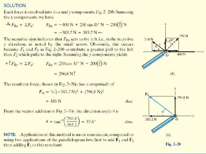
Example 3 The link is subjected to two forces F 1 and F 2. Determine the magnitude and orientation of the resultant force.
Solution Scalar Notation
Solution Resultant Force From vector addition, Direction angle θ is
Solution Cartesian Vector Notation F 1 = { 600 cos 30°i + 600 sin 30°j } N F 2 = { -400 sin 45°i + 400 cos 45°j } N Thus, FR = F 1 + F 2 = (600 cos 30°N - 400 sin 45°N)i + (600 sin 30°N + 400 cos 45°N)j = {236. 8 i + 582. 8 j}N
Problem 4: Determine the magnitude of the resultant force and its direction, measured clockwise from the positive x axis. Given: F 1 : = 70 N F 2 : = 50 N F 3 : = 65 N θ : = 30 deg φ : = 45 deg
Solution : →+ FRX : = F 1 + F 2⋅cos(θ) − F 3⋅cos(φ) +↑ FRY : = −F 2⋅ sin(θ) − F 3⋅ sin(φ) FR = FRX 2 + FRY 2 ( θ = tan-1 FRY FRX θ = 46. 5 deg ( FR = 97. 8 N
Problem 5:
2. 5 Cartesian Vectors • Right-Handed Coordinate System A rectangular or Cartesian coordinate system is said to be right-handed provided: - Thumb of right hand points in the direction of the positive z axis when the right-hand fingers are curled about this axis and directed from the positive x towards the positive y axis
2. 5 Cartesian Vectors • Rectangular Components of a Vector - A vector A may have one, two or three rectangular components along the x, y and z axes, depending on orientation - By two successive application of the parallelogram law A = A’ + Az A’ = Ax + Ay - Combing the equations, A can be expressed as A = Ax + Ay + Az
2. 5 Cartesian Vectors • Unit Vector - Direction of A can be specified using a unit vector - Unit vector has a magnitude of 1 - If A is a vector having a magnitude of A ≠ 0, unit vector having the same direction as A is expressed by u. A = A / A So that A = A u. A
2. 5 Cartesian Vectors • Unit Vector - Since A is of a certain type, like force vector, a proper set of units are used for the description - Magnitude A has the same sets of units, hence unit vector is dimensionless - A ( a positive scalar) defines magnitude of A - u. A defines the direction and sense of A
2. 5 Cartesian Vectors • Cartesian Unit Vectors - Cartesian unit vectors, i, j and k are used to designate the directions of x, y and z axes - Sense (or arrowhead) of these vectors are described by a plus or minus sign (depending on pointing towards the positive or negative axes)
2. 5 Cartesian Vectors • Cartesian Vector Representations - Three components of A act in the positive i, j and k directions A = A x i + A y j + A Zk *Note the magnitude and direction of each components are separated, easing vector algebraic operations.
2. 5 Cartesian Vectors • Magnitude of a Cartesian Vector - From the colored triangle, - From the shaded triangle, - Combining the equations gives magnitude of A
2. 5 Cartesian Vectors • Direction of a Cartesian Vector - Orientation of A is defined as the coordinate direction angles α, β and γ measured between the tail of A and the positive x, y and z axes - 0° ≤ α, β and γ ≤ 180 °
2. 5 Cartesian Vectors • Direction of a Cartesian Vector - For angles α, (blue colored triangles), we calculate the direction cosines of A
2. 5 Cartesian Vectors • Direction of a Cartesian Vector - For angles β, (blue colored triangles), we calculate the direction cosines of A
2. 5 Cartesian Vectors • Direction of a Cartesian Vector - For angles γ, (blue colored triangles), we calculate the direction cosines of A
2. 5 Cartesian Vectors • Direction of a Cartesian Vector - Angles α, β and γ can be determined by the inverse cosines - Given Then, A = A x i + A y j + A Zk u. A = A /A = (Ax/A)i + (Ay/A)j + (AZ/A)k where
2. 5 Cartesian Vectors • Direction of a Cartesian Vector - u. A can also be expressed as u. A = cosαi + cosβj + cosγk - Since and magnitude of u. A = 1, -A as expressed in Cartesian vector form A = Au. A = Acosαi + Acosβj + Acosγk = A x i + A y j + A Zk
2. 6 Addition and Subtraction of Cartesian Vectors Example Given: A = Axi + Ayj + AZk and B = Bxi + Byj + BZk Vector Addition Resultant R = A + B = (Ax + Bx)i + (Ay + By )j + (AZ + BZ) k Vector Substraction Resultant R = A - B = (Ax - Bx)i + (Ay - By )j + (AZ - BZ) k
2. 6 Addition and Subtraction of Cartesian Vectors • Concurrent Force Systems - Force resultant is the vector sum of all the forces in the system FR = ∑Fxi + ∑Fyj + ∑Fzk where ∑Fx , ∑Fy and ∑Fz represent the algebraic sums of the x, y and z or i, j or k components of each force in the system
2. 6 Addition and Subtraction of Cartesian Vectors • Force, F that the tie down rope exerts on the ground support at O is directed along the rope • Angles α, β and γ can be solved with axes x, y and z
2. 6 Addition and Subtraction of Cartesian Vectors • Cosines of their values forms a unit vector u that acts in the direction of the rope • Force F has a magnitude of F F = Fu = Fcosαi + Fcosβj + Fcosγk
2. 6 Addition and Subtraction of Cartesian Vectors Example 4 Express the force F as Cartesian vector
2. 6 Addition and Subtraction of Cartesian Vectors Solution Since two angles are specified, the third angle is found by Two possibilities exit, namely or
2. 6 Addition and Subtraction of Cartesian Vectors Solution By inspection, α = 60° since Fx is in the +x direction Given F = 200 N F = Fcosαi + Fcosβj + Fcosγk = (200 cos 60°N)i + (200 cos 60°N)j + (200 cos 45°N)k = {100. 0 i + 100. 0 j + 141. 4 k}N Checking:
Assume lb = N
2. 7 Position Vectors • x, y, z Coordinates - Right-handed coordinate system - Positive z axis points upwards, measuring the height of an object or the altitude of a point - Points are measured relative to the origin, O.
2. 7 Position Vectors • x, y, z Coordinates Example 5: For Point A, x. A = +4 m along the x axis, y. A = +2 m along the y axis and z. A = -6 m along the z axis. Thus, A (4, 2, -6) Similarly, B (0, 2, 0) and C (6, -1, 4)
2. 7 Position Vectors • Position Vector - Position vector r is defined as a fixed vector which locates a point in space relative to another point. Eg: If r extends from the origin, O to point P (x, y, z) then, in Cartesian vector form r = xi + yj + zk
2. 7 Position Vectors • Position Vector - Position vector maybe directed from point A to point B - Designated by r or r. AB Vector addition gives r. A + r = r. B Solving r = r. B – r. A = (x. B – x. A)i + (y. B – y. A)j + (z. B –z. A)k or r = (x. B – x. A)i + (y. B – y. A)j + (z. B –z. A)k
2. 7 Position Vectors • Position Vector - The i, j, k components of the positive vector r may be formed by taking the coordinates of the tail, A (x. A, y. A, z. A) and subtract them from the head B (x. B, y. B, z. B) Note the head to tail vector addition of the three components
2. 7 Position Vectors • Length and direction of cable AB can be found by measuring A and B using the x, y, z axes • Position vector r can be established • Magnitude r represent the length of cable
2. 7 Position Vectors • Angles, α, β and γ represent the direction of the cable • Unit vector, u = r/r
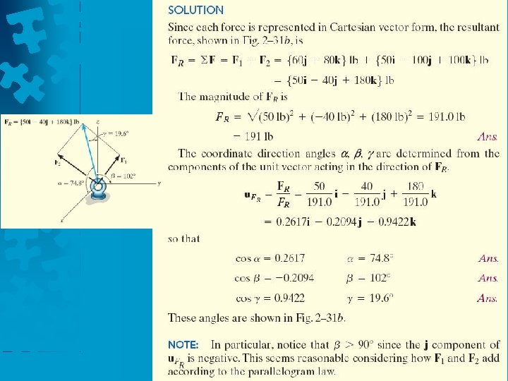
2. 7 Position Vectors Example 6 An elastic rubber band is attached to points A and B. Determine its length and its direction measured from A towards B.
2. 7 Position Vectors Solution Position vector r = [-2 m – 1 m]i + [2 m – 0]j + [3 m – (-3 m)]k = {-3 i + 2 j + 6 k}m Magnitude = length of the rubber band =7 m Unit vector in the director of r u = r /r = -3/7 i + 2/7 j + 6/7 k
2. 7 Position Vectors • Solution α = cos-1(-3/7) = 115° β = cos-1(2/7) = 73. 4° γ = cos-1(6/7) = 31. 0°
2. 8 Force Vector Directed along a Line • In 3 D problems, direction of F is specified by 2 points, through which its line of action lies • F can be formulated as a Cartesian vector F = F u = F (r/r) Note that F has units of forces (N) unlike r, with units of length (m)
2. 8 Force Vector Directed along a Line • Force F acting along the chain can be presented as a Cartesian vector by - Establish x, y, z axes - Form a position vector r along length of chain
2. 8 Force Vector Directed along a Line • Unit vector, u = r/r that defines the direction of both the chain and the force • We get F = Fu
2. 8 Force Vector Directed along a Line Example 7 The man pulls on the cord with a force of 350 N. Represent this force acting on the support A, as a Cartesian vector and determine its direction.
2. 8 Force Vector Directed along a Line Solution End points of the cord are A (0 m, 7. 5 m) and B (3 m, -2 m, 1. 5 m) r = (3 m – 0 m)i + (-2 m – 0 m)j + (1. 5 m – 7. 5 m)k = {3 i – 2 j – 6 k}m Magnitude = length of cord AB = 7 m Unit vector, u = r /r = 3/7 i - 2/7 j - 6/7 k
2. 8 Force Vector Directed along a Line Solution Force F has a magnitude of 350 N, direction specified by u F = Fu = 350 N(3/7 i - 2/7 j - 6/7 k) = {150 i - 100 j - 300 k} N α = cos-1(3/7) = 64. 6° β = cos-1(-2/7) = 107° γ = cos-1(-6/7) = 149°
Problem 6: • Determine the magnitude and coordinate direction angles of the resultant force acting at point A. Answer: FR = 316 N α =60. 1 o β =74. 6 o γ=145. 6 o
2. 9 Dot Product • Dot product of vectors A and B is written as A·B (Read A dot B) • Define the magnitudes of A and B and the angle between their tails A·B = AB cos θ where 0°≤ θ ≤ 180°
2. 9 Dot Product Laws of Operation 1. Commutative law A·B = B·A 2. Multiplication by a scalar a(A·B) = (a. A)·B = A·(a. B) = (A·B)a 3. Distribution law A·(B + D) = (A·B) + (A·D)
2. 9 Dot Product Cartesian Vector Formulation - Dot product of Cartesian unit vectors Eg: i·i = (1)(1) cos 0° = 1 and i·j = (1)(1) cos 90° = 0 - Similarly i·i = 1 j·j = 1 k·k = 1 i·j = 0 i·k = 0 j·k = 0
2. 9 Dot Product • Cartesian Vector Formulation - Dot product of 2 vectors A and B A·B = (Axi + Ayj + Azk)· (Bxi + Byj + Bzk) = Ax. Bx(i·i) + Ax. By(i·j) + Ax. Bz(i·k) + Ay. Bx(j·i) + Ay. By(j·j) + Ay. Bz(j·k) + Az. Bx(k·i) + Az. By(k·j) + Az. Bz(k·k) = A x. B x + A y. B y + A z B z Note: since result is a scalar, be careful of including any unit vectors in the result