Chapter 2 Force Vectors Engineering Mechanics Statics Ahmad


 Determine the magnitude of the resultant force and its")
")


")


 =")

 1. Establish coordinate of A and B 2. Determine")


 • Determine the magnitude and coordinate direction angles of")


 • Determine the magnitude and coordinate direction angles of")


 parallel to")


- Slides: 86
Chapter 2: Force Vectors Engineering Mechanics: Statics Ahmad Faizal bin Salleh 2017/2018
Objectives • To show to add forces and resolve them into components using the graphical method (Parallelogram Law) and trigonometries. • To show to add forces and resolve them using rectangular component method. • To express force and position in Cartesian vector form and explain how to determine the vector’s magnitude and direction. • To introduce the dot product in order to determine the angle between two vectors or the projection of one vector onto another.
Chapter Outline • • • Scalars and Vectors Vector Operations Vector Addition of Forces Addition of a System of Coplanar Forces Cartesian Vectors
Chapter Outline • Addition and Subtraction of Cartesian Vectors • Position Vectors • Force Vector Directed along a Line • Dot Product
2. 1 Scalars and Vectors • Scalar – A quantity characterized by a positive or negative number that can be specified by its magnitude. time mass temperature
2. 1 Scalars and Vectors • Vector – A quantity that has both magnitude and direction Eg: Position, force and moment – Represent by a letter with an arrow over it such as – Magnitude is designated as or simply A – In this subject, vector is presented as A and its magnitude (positive quantity) as A
2. 1 Scalars and Vectors Vector – A quantity that has both magnitude and direction – Represented graphically as an arrow – Length of arrow = Magnitude of Vector – Angle between the reference axis and arrow’s line of action = Direction of Vector – Arrowhead = Sense of Vector
2. 2 Vector Operations Vector Addition - Addition of two vectors A and B gives a resultant vector R by the parallelogram law. - Resultant vector, R can be found by triangle construction.
2. 2 Vector Operations Vector Addition Graphically adding vectors using “tail to tail” approach. Graphically adding vectors using “tail to head” approach.
2. 2 Vector Operations Vector Subtraction - Special case of addition Eg: R’ = A – B = A + ( - B ) - Rules of Vector Addition Applies
2. 3 Vector Addition Forces • When two or more forces are added, successive applications of the parallelogram law is carried out to find the resultant Example Forces F 1, F 2 and F 3 acts at a point O a) First, find resultant of F 1 + F 2 Solution; Resultant, • FR = ( F 1 + F 2 ) + F 3
Procedure of Analysis Parallelogram Law is used together with Trigonometry for finding resultant or resolving vector into its components.
Example 1 Use graphical method and trigonometries to resolve the horizontal 600 -N force in Figure below into components acting along the u and v axes and determine the magnitudes of these components. One vectors to be resolved into components (in this case, two components). Explain on the case where u and v axes are perpendicular. 600 N
600 N N N 600 N
Example 2 The screw eye is subjected to two forces F 1 and F 2. Use graphical representation and trigonometries to determine the magnitude and the direction of the resultant force. 2 vectors to be added to produce a resultant vector. Ask students to resolve each vector into axes. In this case axes are perpendicular to each other.
Parallelogram Law Graphical representation of vector addition Unknown: magnitude of FR and angle θ
Trigonometry Determining value from “Graphical Representation” Law of Cosines
Trigonometry Determining value from “Graphical Representation” Law of Sines Direction Φ of FR measured from the horizontal
Problem 1: Use graphical representation and trigonometries to determine the magnitude of the resultant force FR = F 1 + F 2 and its direction, measured counterclockwise from the positive x axis. 800 N 60 o 450 N 75 o
Important Points Parallelogram Law is a “graphical method” use together with law of sines and law of cosines for a) resolving vector into its components. b) determining the resultant vector.
2. 4 Addition of a System of Coplanar Forces So far, the addition of vectors were done using graphical method and trigonometry. If more than two forces involve, extensive graphical method and trigonometric calculations were required. In this subsection, the “rectangular component method” were used rather than graphical method and trigonometries. graphical method → parallelogram law followed by trigonometries.
2. 4 Addition of a System of Coplanar Forces OBJECTIVES • To express force using the Scalar and Cartesian vector notation. • To find the resultant for more than 2 forces.
Example 3 The link is subjected to two forces F 1 and F 2. Use rectangular component method to determine the magnitude and orientation of the resultant force. This was done using Graphical Method in Example 2. Compare with Example 1 too
Solve using scalar notation
Solve using scalar notation Resultant Force From vector addition, direction angle θ is
Solve using vector notation F 1 = { 100 cos 15°i + 100 sin 15°j } N F 2 = { 150 sin 10°i + 150 cos 10°j } N Thus, FR = F 1 + F 2 = (100 cos 15°N + 150 sin 10°N)i + (100 sin 15°N + 150 cos 10°N)j = {? i + ? j}N
In scalar notation, we determine the resultant component in x and y direction first, then, we use pythagoras theorem to determine the resultant. Use tangent to determine direction of the resultant force. In vector notation, we determine the each force using its x and y component and unit vector. Then, we add both vectors and represent it using unit vectors in x and y direction. In coplanar case, both method could be used to solve for resultant force.
Example 4 The link is subjected to two forces F 1 and F 2. Use rectangular component method to determine the magnitude of the resultant force.
Scalar Notation
Solve using vector notation F 1 = { -200 sin 30°i + 200 cos 30°j } N F 2 = { 260(12/13) i + -260(5/13) j } N Thus, FR = F 1 + F 2 = (-200 sin 30°N + 260 sin 45°N)i + (200 cos 30°N + -260(5/13) N)j = {140 i + 73 j}N
Exe 1 (Submit during class) Determine the magnitude of the resultant force and its direction, measured clockwise from the positive x axis. Given: F 1 : = 70 N F 2 : = 50 N F 3 : = 65 N θ : = 30 deg φ : = 45 deg
Exe 2 (Submit during class)
2. 5 Cartesian Vectors • Right-Handed Coordinate System
2. 5 Cartesian Vectors • Rectangular Components of a Vector A can be expressed as A = Ax + Ay + Az
2. 5 Cartesian Vectors • Unit Vector - Direction of A can be specified using a unit vector - Magnitude = 1 - If A is a vector having a magnitude of A ≠ 0, unit vector having the same direction as A is expressed by u. A = A / A So that , A = A u. A
2. 5 Cartesian Vectors • Cartesian Unit Vectors - Cartesian unit vectors, i, j and k are used to designate the directions of x, y and z axes - Sense (or arrowhead) of these vectors are described by a plus or minus sign (depending on pointing towards the positive or negative axes)
2. 5 Cartesian Vectors Magnitude of a Cartesian Vector - From the colored triangle, - From the shaded triangle, - the equations gives magnitude of A
2. 5 Cartesian Vectors • Direction of a Cartesian Vector Orientation of A is defined as the coordinate direction angles α, β and γ measured between the tail of A and the positive x, y and z axes. - 0° ≤ α, β and γ ≤ 180 °
2. 5 Cartesian Vectors • Direction of a Cartesian Vector For angles α, (blue colored triangles), we calculate the direction cosines of A A α Ax View from plane consists of vector A and Ax
2. 5 Cartesian Vectors • Direction of a Cartesian Vector - For angles β, (blue colored triangles), we calculate the direction cosines of A
2. 5 Cartesian Vectors • Direction of a Cartesian Vector - For angles γ, (blue colored triangles), we calculate the direction cosines of A
2. 5 Cartesian Vectors • Expressing unit vector using direction cosines Given Then, vector where continue. . . A = Axi + Ayj + AZk scalar u. A = A /A = (Ax/A)i + (Ay/A)j + (AZ/A)k
2. 5 Cartesian Vectors • Expressing unit vector using direction cosines u. A = cosαi + cosβj + cosγk - Since and magnitude of u. A = 1, - A as expressed in Cartesian vector form A = Au. A = Acosαi + Acosβj + Acosγk = Axi + Ayj + AZk
Wed 06092017 1005 am
Establishing a Vector Example 5 Express the force F as Cartesian vector
Establishing a Vector Solution Since two angles are specified, the third angle is found by Two possibilities exit, namely or
Establishing a Vector Solution By inspection, α = 60° since Fx is in the +x direction Given F = 200 N F = Fcosαi + Fcosβj + Fcosγk = (200 cos 60°N)i + (200 cos 60°N)j + (200 cos 45°N)k = {100. 0 i + 100. 0 j + 141. 4 k}N Checking:
2. 6 Addition and Subtraction of Cartesian Vectors Example Given: A = Axi + Ayj + AZk and B = Bxi + Byj + BZk Vector Addition Resultant R = A + B = (Ax + Bx)i + (Ay + By )j + (AZ + BZ) k Vector Substraction Resultant R = A - B = (Ax - Bx)i + (Ay - By )j + (AZ - BZ) k
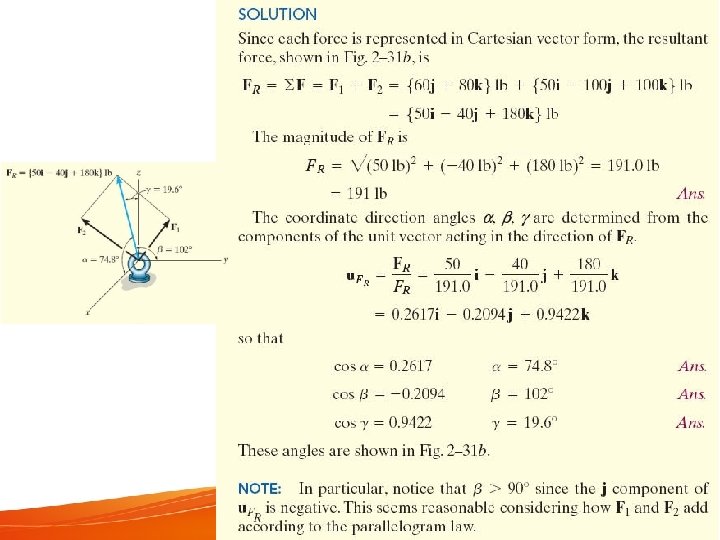
Addition and Subtraction of Cartesian Vectors EXAMPLE 6 Assume lb = N
Exe 3 (Assignment Q 1)
2. 7 Position Vectors In this section, the position vector will be introduced. It is useful to define two points in space. The position vector is defined in Cartesian coordinate system.
Position Vectors We start with identifying the coordinates of point A, B and C.
Position Vectors Formulating position vector from coordinates Position vector r is defined as a fixed vector which locates a point in space relative to another point. Eg: If r extends from the origin, O to point P (x, y, z) then, in Cartesian vector form r = xi + yj + zk
Position Vectors Position vector maybe directed from point A to point B Designated by r or r. AB Vector addition gives, r. A + r = r. B Solving r = r. B – r. A = (x. B – x. A)i + (y. B – y. A)j + (z. B –z. A)k or r = (x. B – x. A)i + (y. B – y. A)j + (z. B –z. A)k
Position Vectors Utilize the concept of determining position vector from coordinates to determine the position vector CB and BA.
Position Vectors Still remember Unit Vector? Utilize the concept of unit vector to determine the position vector CB and BA.
Position Vectors Example 7 An elastic rubber band is attached to points A and B. Determine its length and its direction measured from A towards B.
Position Vectors Determine position and unit vector Solution Position vector r = [-2 m – 1 m]i + [2 m – 0]j + [3 m – (-3 m)]k = {-3 i + 2 j + 6 k}m Magnitude = length of the rubber band =7 m Unit vector in the director of r u = r /r = -3/7 i + 2/7 j + 6/7 k
Position Vectors Direction of AB using direction cosines • Solution α = cos-1(-3/7) = 115° β = cos-1(2/7) = 73. 4° γ = cos-1(6/7) = 31. 0°
Important Points To establish a vector directed from A to B (obtain position vector r. AB), the coordinate of B should be substracted from coordinate of A.
Exercise 4 (Submit During Class) 1. Establish coordinate of A and B 2. Determine the position vector, r. AB
2. 8 Force Vector Directed along a Line In this section, utilizing the concept of unit vector derived from position vector, student will formulate Cartesion force vector between two point in space.
Force Vector Directed along a Line • In 3 D problems, direction of F is specified by 2 points, through which its line of action lies • F can be formulated as a Cartesian vector F = F u = F (r/r) Note that F has units of forces (N) unlike r, with units of length (m)
Force Vector Directed along a Line • Force F acting along the chain can be presented as a Cartesian vector by - Establish x, y, z axes - Form a position vector r along length of chain
Force Vector Directed along a Line • Unit vector, u = r/r that defines the direction of both the chain and the force • We get F = Fu
Force Vector Directed along a Line Example 8 The man pulls on the cord with a force of 350 N. Represent this force acting on the support A, as a Cartesian vector and determine its direction.
Force Vector Directed along a Line Solution End points of the cord are A (0 m, 7. 5 m) and B (3 m, -2 m, 1. 5 m) r = (3 m – 0 m)i + (-2 m – 0 m)j + (1. 5 m – 7. 5 m)k = {3 i – 2 j – 6 k}m Magnitude = length of cord AB = 7 m Unit vector, u = r /r = 3/7 i - 2/7 j - 6/7 k
Exe 5 (Submit during class) • Determine the magnitude and coordinate direction angles of the resultant force acting at point A. Answer: FR = 316 N α =60. 1 o β =74. 6 o γ=145. 6 o
Force Vector Directed along a Line Solution Force F has a magnitude of 350 N, direction specified by u F = Fu = 350 N(3/7 i - 2/7 j - 6/7 k) = {150 i - 100 j - 300 k} N α = cos-1(3/7) = 64. 6° β = cos-1(-2/7) = 107° γ = cos-1(-6/7) = 149°
Monday, 2 pm 11 September 2017
Exe 5 (Solve this first) • Determine the magnitude and coordinate direction angles of the resultant force acting at point A. Answer: FR = 316 N α =60. 1 o β =74. 6 o γ=145. 6 o
IMPORTANT POINTS You could established a force vector along a line, if the magnitude of the force vector, coordinates that lie on the line are given. The steps are: 1. Utilize the coordinates to establish position vector. 2. From position vector, establish unit vector. 3. Utilize F = Fu, to establish force vector.
2. 9 Dot Product • Dot product of vectors A and B is written as A·B (Read A dot B) • Define the magnitudes of A and B and the angle between their tails A·B = AB cos θ where 0°≤ θ ≤ 180°
2. 9 Dot Product Laws of Operation 1. Commutative law A·B = B·A 2. Multiplication by a scalar a(A·B) = (a. A)·B = A·(a. B) = (A·B)a 3. Distribution law A·(B + D) = (A·B) + (A·D)
2. 9 Dot Product Cartesian Vector Formulation - Dot product of Cartesian unit vectors Eg: i·i = (1)(1) cos 0° = 1 and i·j = (1)(1) cos 90° = 0 - Similarly i·i = 1 j·j = 1 k·k = 1 i·j = 0 i·k = 0 j·k = 0
2. 9 Dot Product • Cartesian Vector Formulation - Dot product of 2 vectors A and B A·B = (Axi + Ayj + Azk)· (Bxi + Byj + Bzk) = Ax. Bx(i·i) + Ax. By(i·j) + Ax. Bz(i·k) + Ay. Bx(j·i) + Ay. By(j·j) + Ay. Bz(j·k) + Az. Bx(k·i) + Az. By(k·j) + Az. Bz(k·k) = Ax. Bx + Ay. By + Az. Bz Note: since result is a scalar, be careful of including any unit vectors in the result
2. 9 Dot Product Assume you have vector A, and you would like to obtain the component of vector A in x direction and express it as a vector, Ax. If magnitude of vector A and angle between vector A and x axis are given, you could do it this way, y A Ɵ = 60° Ax x Scalar: Ax = A cos Ɵ = √ 2 * cos 60 = √ 2 * 0. 5 N Express vector A in x direction, then, Ax = √ 2 * 0. 5 i N We could solve the above problem using Dot Product of a vector. Next slide. . .
2. 9 Dot Product Assume that vector A is given as, A = 1 i + 1 j (angle between vector A and x axis was not given). In order to obtain the component of vector A in x direction, you could carry out a dot product between vector A and unit vector in x direction, ux. A unit vector in x direction is commonly express as i and has a magnitude of 1. Therefore ux = 1 i A·ux = |(1 i + 1 j)|*|1 i |*cos 60°= √ 2*0. 5 N A Ax = √ 2*0. 5 N Here the answer is in scalar, you need to convert Ax into a vector, Ax (The question ask you to get component of vector A in x direction and express it as a vector. . . BE VERY CAREFULL!!!!!!) Thus, Ax = Axi = √ 2*0. 5 N i Same answer as previous slide. Ax
2. 9 Dot Product In slide 78, angle, magnitude of vector and unit vector was given. In slide 79, only vector A and unit vector in x direction was given. In both slides, you still manage to get the component of A in x direction.
Example 9 Application of Dot Product - 1 Determining angle between two vectors
EXERCISE 2 -116
EXAMPLE 10 Application of Dot Product - 2 Determining component of a vector parallel and perpendicular to a line Parallel and perpendicular to line AB
EXTRA KNOWLEDGE Determining Magnitude of Projection (*NOT A COMPONENT of A VECTOR*) parallel to a line (axes v and u). Axes v and u are NOT PERPENDICULAR TO EACH OTHER. The difference between obtaining component of a force and obtaining magnitude of the projection of a force. How to obtain component of force F in u and v direction? Use parallelogram law and trigonometries.
Important Points Dot product is useful for, 1. Determining an angle between two vector. 2. Determining a component of a vector parallel and perpendicular to a line. This is ONLY TRUE for Cartesian coordinate system (Axes are perpendicular towards each other).
What did you learn so far? 1. The difference between graphical method and rectangular component method to resolve force to its components and determine resultant force in either 2 D or 3 D coordinate system. 2. 2 D and 3 D vectors properties and representation. 3. Dot product of vectors and its application.