
CHAPTER 2 Drafting Equipment Media and Reproduction Methods




- Slides: 52
CHAPTER 2 Drafting Equipment, Media, and Reproduction Methods
Learning Objectives • Describe and demonstrate the use of manual drafting equipment and supplies • Explain the concept of drawing scale, and identify common inch and metric scales • Read metric, civil engineer, architect, and mechanical scales
Learning Objectives • Describe and use drafting media, sheet sizes, and sheet blocks and symbols • Explain common drawing reproduction methods
Manual Drafting (Hand Drafting) • Mostly replaced by computer-aided design and drafting (CADD) • Manual drafting and CADD require understanding the basics of drafting • Scale • Sheet size • Sheet format
Manual Drafting Equipment and Supplies • Historical reference • Still valuable for: • Sketching • Taking measurements • Other related activities • Still used by some companies for certain applications
Automatic Pencils • Common for manual drafting, sketching, and office use • Do not require sharpening • Available in several different lead sizes • Combination of 0. 5, 0. 7, and 0. 9 mm pencils and leads good for sketching and daily use
Lead Grades • Different grades of hardness for specific techniques • 2 H and H good for typical daily office use • 2 H to F for thick lines • 4 H to H for thin lines • 6 H or 4 H for construction lines and guidelines
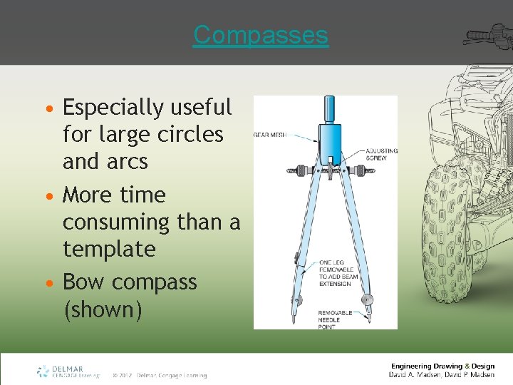
Compasses • Especially useful for large circles and arcs • More time consuming than a template • Bow compass (shown)
Dividers • Bow • Proportional
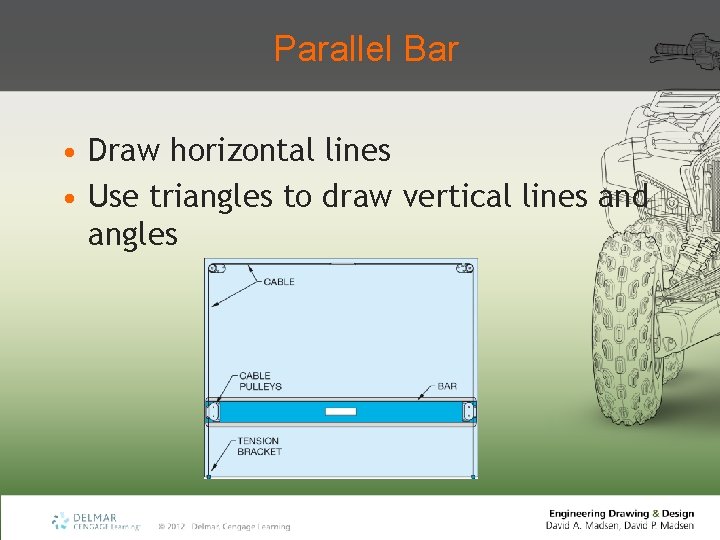
Parallel Bar • Draw horizontal lines • Use triangles to draw vertical lines and angles
Triangles • • Straightedge Draw angles Connect points 30°– 60° triangle • Angles of 30°– 60°– 90° • 45° triangle • Angles of 45°– 90°
Templates • • Circles Ellipses Letters Specific requirements and drafting disciplines • Examples: Architectural symbols Electronic schematic symbols
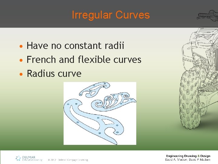
Irregular Curves • Have no constant radii • French and flexible curves • Radius curve
Drafting Machines • Generally take the place of triangles and parallel bars • Maintains a horizontal and vertical relationship between scales • Scales serve as straightedges • Protractor allows scales to be set quickly at any angle
Arm and Track Drafting Machines
Scale • Measurement instrument • Specific scales for mechanical, • • • architectural, civil, and metric drawings Used by manual drafters to help create scaled drawings Still useful for sketching, taking measurements, and related tasks Four basic shapes
Scale • Concept • A universal and critical design and drafting concept
Drawing Scale • Drawings are scaled so the objects represented can be illustrated clearly on standard sizes of paper • Depends on: • Actual size of the objects drawn • Amount of detail to show • Media size • Amount of dimensioning and notes required
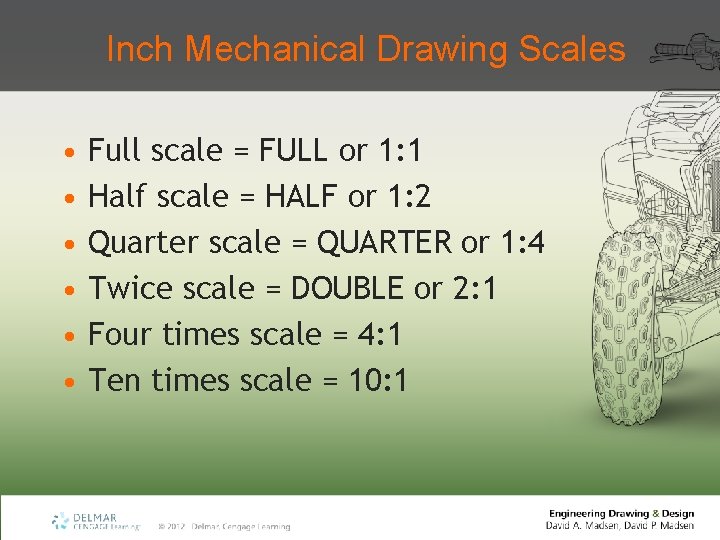
Inch Mechanical Drawing Scales • • • Full scale = FULL or 1: 1 Half scale = HALF or 1: 2 Quarter scale = QUARTER or 1: 4 Twice scale = DOUBLE or 2: 1 Four times scale = 4: 1 Ten times scale = 10: 1
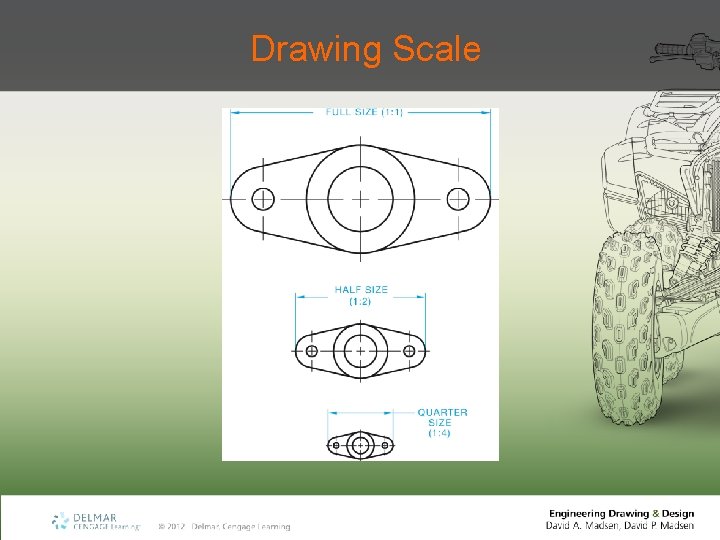
Drawing Scale
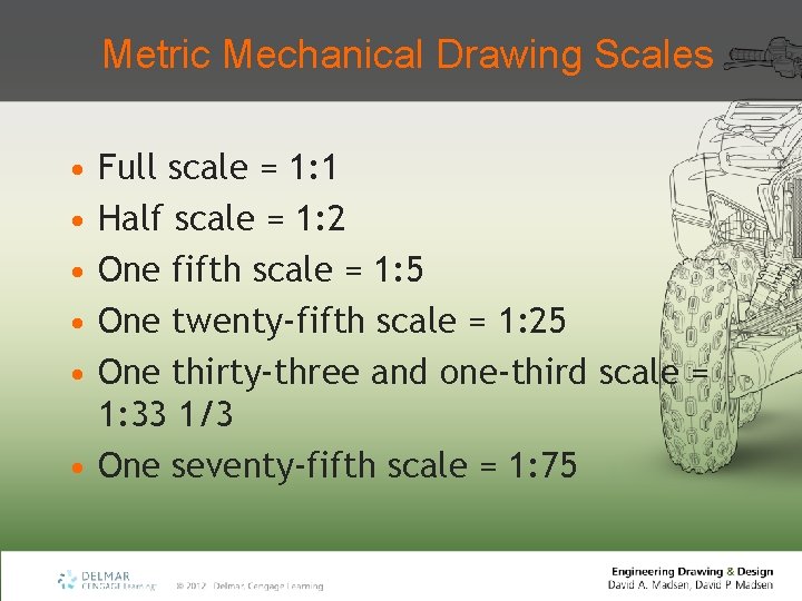
Metric Mechanical Drawing Scales • • • Full scale = 1: 1 Half scale = 1: 2 One fifth scale = 1: 5 One twenty-fifth scale = 1: 25 One thirty-three and one-third scale = 1: 33 1/3 • One seventy-fifth scale = 1: 75
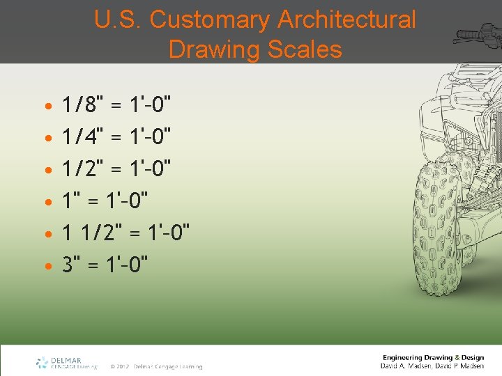
U. S. Customary Architectural Drawing Scales • • • 1/8" = 1'– 0" 1/4" = 1'– 0" 1/2" = 1'– 0" 1 1/2" = 1'– 0" 3" = 1'– 0"
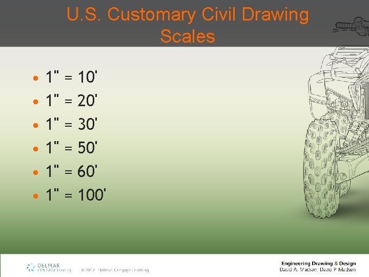
U. S. Customary Civil Drawing Scales • • • 1" 1" 1" = = = 10' 20' 30' 50' 60' 100'
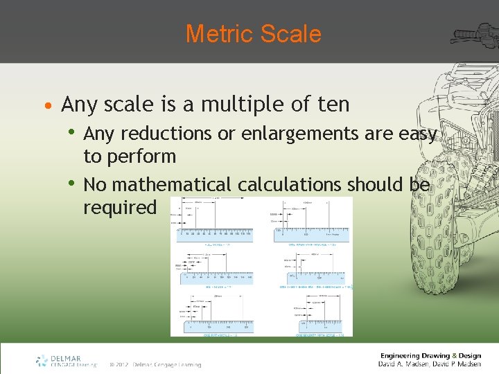
Metric Scale • Any scale is a multiple of ten • Any reductions or enlargements are easy • to perform No mathematical calculations should be required
Civil Engineer’s Scale Divisions Ratio Scales Used with This Division 10 1: 1 1" = 1" 1" = 1' 1" = 100' 20 1: 2 1" = 2" 1" = 2' 1" = 200' 30 1: 3 1" = 3" 1" = 3' 1" = 300' 40 1: 4 1" = 4" 1" = 4' 1" = 400' 50 1: 5 1" = 5" 1" = 5' 1" = 500' 60 1: 6 1" = 6" 1" = 6' 1" = 600"
Civil Engineer’s Scale • Any multiple of ten • 10 scale often used for mechanical drawings at full, decimal-inch scale (1: 1) • 20 scale common for mechanical drawings at half scale (1: 2) • 20 scale used for scales of 1" = 2', 1" = 20', and 1" = 200' • 50 scale popular in civil drafting
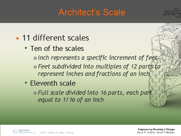
Architect’s Scale • 11 different scales • Ten of the scales Inch represents a specific increment of feet Feet subdivided into multiples of 12 parts to represent inches and fractions of an inch • Eleventh scale Full scale divided into 16 parts, each part equal to 1/16 of an inch
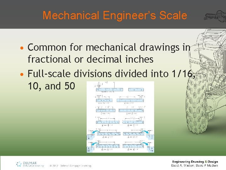
Mechanical Engineer’s Scale • Common for mechanical drawings in fractional or decimal inches • Full-scale divisions divided into 1/16, 10, and 50
Vellum • Most common drafting media • Inexpensive • Good smoothness, erasability, and transparency • Less durable and dimensionally stable • Appropriate for regular graphite leads • Well drawn graphite on vellum reproduces well
Polyester Film • Mylar® • Expensive • Excellent durability, smoothness, erasability, dimensional stability, and transparency • Best with ink or special polyester leads • Well drawn ink on polyester film reproduces the best
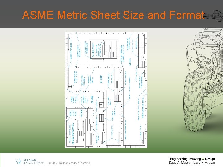
Sheet Size and Format • Standards for sheet size and format • ASME Y 14. 1, Decimal Inch Drawing Sheet • • Size and Format ASME Y 14. 1 M, Metric Drawing Sheet Size and Format Architectural, civil and structural drawings often use unique sheet format and may use unique sheet sizes
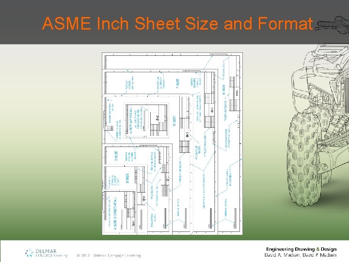
ASME Inch Sheet Size and Format [Insert Figure 2. 31]
ASME Metric Sheet Size and Format
Selecting a Sheet Size • Size of objects drawn • Drawing scale • Amount of additional content on the sheet • Border • Title block • Drafting standards and company practice
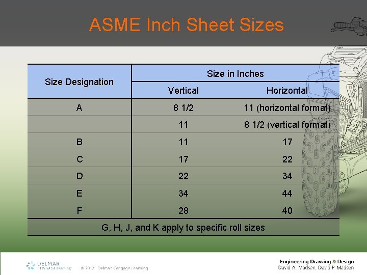
ASME Inch Sheet Sizes Size Designation Size in Inches Vertical Horizontal 8 1/2 11 (horizontal format) 11 8 1/2 (vertical format) B 11 17 C 17 22 D 22 34 E 34 44 F 28 40 A G, H, J, and K apply to specific roll sizes
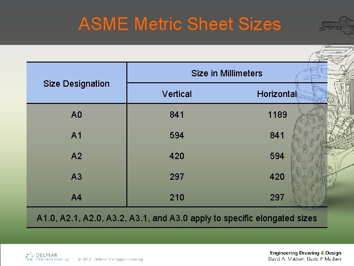
ASME Metric Sheet Sizes Size in Millimeters Size Designation Vertical Horizontal A 0 841 1189 A 1 594 841 A 2 420 594 A 3 297 420 A 4 210 297 A 1. 0, A 2. 1, A 2. 0, A 3. 2, A 3. 1, and A 3. 0 apply to specific elongated sizes
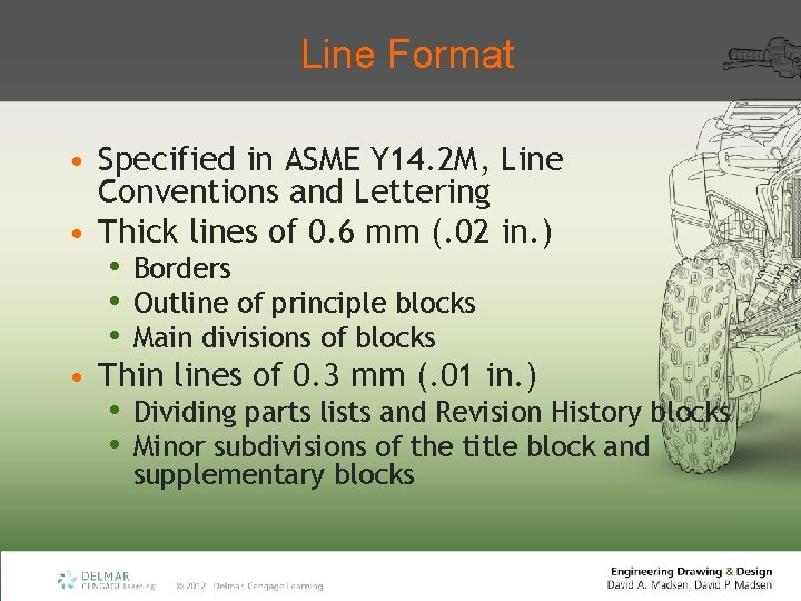
Line Format • Specified in ASME Y 14. 2 M, Line Conventions and Lettering • Thick lines of 0. 6 mm (. 02 in. ) • Borders • Outline of principle blocks • Main divisions of blocks • Thin lines of 0. 3 mm (. 01 in. ) • Dividing parts lists and Revision History blocks • Minor subdivisions of the title block and supplementary blocks
ASME Lettering Style • Vertical uppercase Gothic • Arial, Roman, or similar font when using CADD
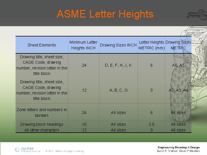
ASME Letter Heights Sheet Elements Minimum Letter Heights Drawing Sizes INCH Heights INCH METRIC (mm) METRIC Drawing title, sheet size, CAGE Code, drawing number, revision letter in the title block . 24 D, E, F, H, J, K 6 A 0, A 1 Drawing title, sheet size, CAGE Code, drawing number, revision letter in the title block . 12 A, B, C, G 3 A 2, A 3, A 4 Zone letters and numbers in borders . 24 All sizes 6 All sizes Drawing block headings All other characters . 10. 12 All sizes 2. 5 3 All sizes
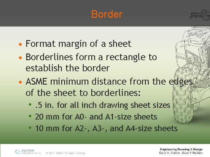
Border • Format margin of a sheet • Borderlines form a rectangle to establish the border • ASME minimum distance from the edges of the sheet to borderlines: • . 5 in. for all inch drawing sheet sizes • 20 mm for A 0 - and A 1 -size sheets • 10 mm for A 2 -, A 3 -, and A 4 -size sheets
Zoning • Allows the drawing to read like a road map • Recommend by ASME standards for all sheets • Optional for A, B, and A 4 size sheets
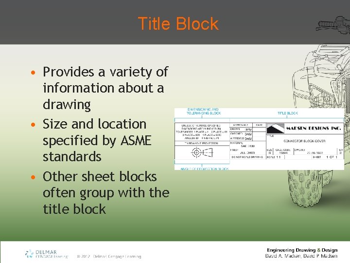
Title Block • Provides a variety of information about a drawing • Size and location specified by ASME standards • Other sheet blocks often group with the title block
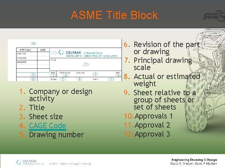
ASME Title Block 1. Company or design activity 2. Title 3. Sheet size 4. CAGE Code 5. Drawing number 6. Revision of the part or drawing 7. Principal drawing scale 8. Actual or estimated weight 9. Sheet relative to a group of sheets or set of sheets 10. Approvals 1 11. Approval 2 12. Approval 3
Angle of Projection Block • Third angle projection • First angle projection
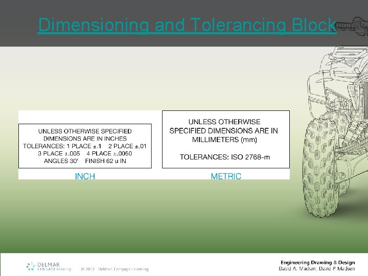
Dimensioning and Tolerancing Block
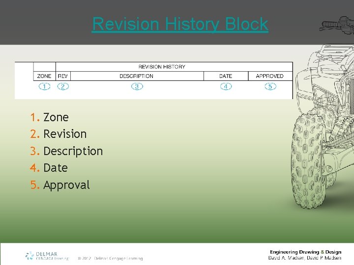
Revision History Block 1. Zone 2. Revision 3. Description 4. Date 5. Approval
Revision Status of Sheets Block • Not required on single-sheet drawings • Horizontal or vertical • Located by the title block or in the area of the Revision History block
Revision Status Notation • ALL SHEETS ARE THE SAME REVISION STATUS • Optional • Next to the title block when the revision status of all sheets is the same
Additional Sheet Blocks and Symbols • Margin drawing number block • Application block • Microfilm alignment arrows
Diazo Reproduction • Ozalid dry prints or blue-line prints • Not an actual blueprint • Mostly replaced by photocopy reproduction and CADD prints
Photocopy Reproduction • Photocopy printers or engineering copiers • Photographically reproduces material, especially by xerography • Advantages over diazo printing
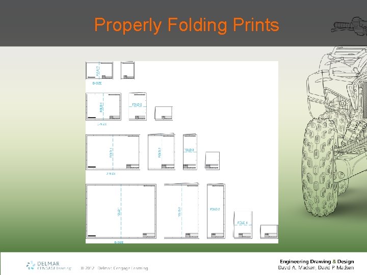
Properly Folding Prints