Chapter 2 Computer Networks Computer Networking A Top


: – run application programs – e. g.")


 divided into “pieces” pieces")


 / 24 =64")


 packet of")


 Data")


 connects end system to")


 two insulated copper wires Category 1: Less expensive and most commonly")
 Ex: TV")


 L=packet length (bits) time")


 dproc = processing delay typically a few microsecs or less")
 R=link bandwidth (bps) L=packet length (bits) a=average packet arrival rate traffic")


 preceding link in buffer has finite capacity when packet")


 ticket (complain) baggage (check) baggage (claim) gates (load)")
 ticket (complain) ticket baggage (check) baggage (claim baggage")


- Slides: 70
Chapter 2 Computer Networks Computer Networking: A Top Down Approach Featuring the Internet, 3 rd edition. Jim Kurose, Keith Ross Addison-Wesley, July 2004. 1
Chapter 2: roadmap 2. 1 Network edge 2. 2 Network core 2. 3 Access Network and physical media 2. 4 Delay & loss in packet-switched networks 2. 5 Protocol layers, service models 2
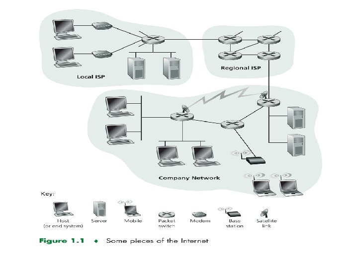
A closer look at network structure: • network edge: applications and hosts • network core: – routers – network of networks • access networks, physical media: communication links
The network edge: • end systems (hosts): – run application programs – e. g. Web, email – at “edge of network” • client/server model – client host requests, receives service from always-on server – e. g. Web browser/server; email client/server • peer-peer model: – minimal (or no) use of dedicated servers – e. g. Gnutella, Ka. Za. A, Skype
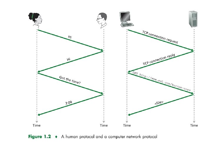
Network edge: connection-oriented service Goal: data transfer between end systems • handshaking: setup (prepare for) data transfer ahead of time – Hello, hello back human protocol – set up “state” in two communicating hosts • TCP - Transmission Control Protocol – Internet’s connectionoriented service TCP service [RFC 793] • reliable, in-order byte-stream data transfer – loss: acknowledgements and retransmissions • flow control: – sender won’t overwhelm receiver • congestion control: – senders “slow down sending rate” when network congested
Network edge: connectionless service Goal: data transfer between end systems – same as before! • UDP - User Datagram Protocol [RFC 768]: – connectionless – unreliable data transfer – no flow control – no congestion control App’s using TCP: • HTTP (Web), FTP (file transfer), Telnet (remote login), SMTP (email) App’s using UDP: • streaming media, teleconferencing, DNS, Internet telephony
Chapter 2: roadmap 2. 1 Network edge 2. 2 Network core 2. 3 Access Network and physical media 2. 4 Delay & loss in packet-switched networks 2. 5 Protocol layers, service models 7
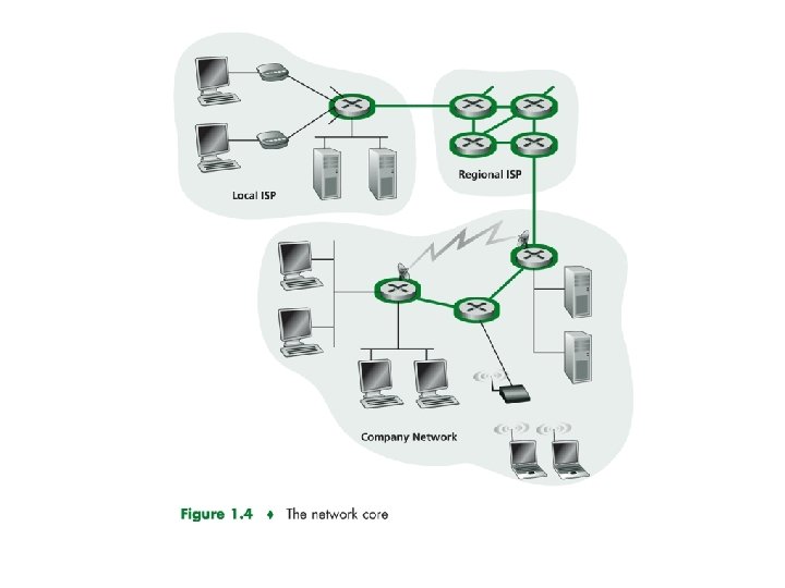
The Network Core mesh of interconnected routers the fundamental question: how is data transferred through net? circuit switching: dedicated circuit per call: telephone net packet-switching: data sent thru net in discrete “chunks” 11
Network Core: Circuit Switching End-end resources reserved for “call” link bandwidth, switch capacity dedicated resources: no sharing circuit-like (guaranteed) performance call setup required 12
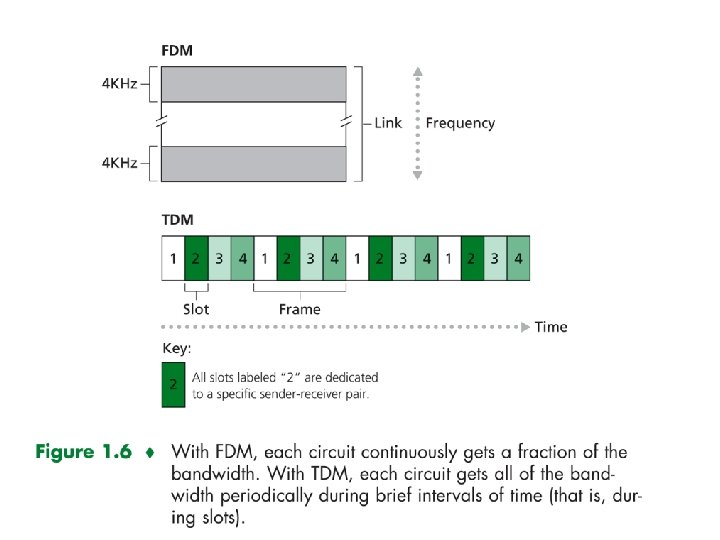
Network Core: Circuit Switching network resources (e. g. , bandwidth) divided into “pieces” pieces allocated to calls dividing link bandwidth into “pieces” frequency division time division resource piece idle if not used by owning call (no sharing) 13
The Circuit in link is implemented FDM or TDM
The Circuit in link is implemented FDM or TDM Circuit Switching: FDM and TDM Example: FDM( Frequency-division multiplexing ) 4 users frequency time TDM( Time-division multiplexing) frequency time 15
Numerical example How long does it take to send a file of 640, 000 bits from host A to host B over a circuit-switched network? All links are 1. 536 Mbps Each link uses TDM with 24 slots/sec 500 msec to establish end-to-end circuit Let’s work it out! 17
Solution: Each Circuit has transmission rate of: (1. 536 Mbps) / 24 =64 Kbps. So it take (640, 000 bits)/ 64 kbps = 10 sec To transmit the file 10 + 0. 5 (establish time)=10. 5 sec
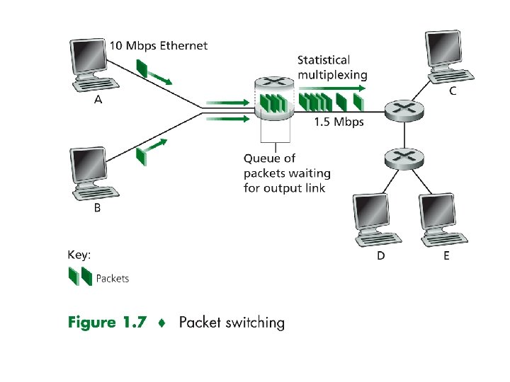
Network Core: Packet Switching Message can contain anything the protocol designer wants. The source brakes long message into smaller chunks of data (packets). Store-and-forward transmission: The switch must receive the entire packet before it can begin onto the outbound link.
Network Core: Packet Switching each end-end data stream divided into packets user A, B packets share network resources each packet uses full link bandwidth resources used as needed Bandwidth division into “pieces” Dedicated allocation Resource reservation resource contention: aggregate resource demand can exceed amount available congestion: packets queue, wait for link use store and forward: packets move one at a time Node receives complete packet before forwarding 20
Packet switching versus circuit switching Is packet switching Great for bursty data resource sharing simpler, no call setup Excessive congestion: packet delay and loss protocols needed for reliable data transfer, congestion control Q: How to provide circuit-like behavior? bandwidth guarantees needed for audio/video apps still an unsolved problem (chapter 7) Q: human analogies of reserved resources (circuit switching) versus on-demand allocation (packet-switching)? 21
Packet-switching: store-and-forward L R Takes L/R seconds to R transmit (push out) packet of L bits on to link or R bps Entire packet must arrive at router before it can be transmitted on next link: store and forward delay = 3 L/R (assuming zero propagation delay) R Example: L = 7. 5 Mbits R = 1. 5 Mbps delay = 15 sec more on delay shortly … 22
Packet-switched networks: forwarding Goal: move packets through routers from source to destination we’ll study several path selection (i. e. routing) algorithms (chapter 4) datagram network: destination address in packet determines next hop routes may change during session analogy: driving, asking directions virtual circuit network: each packet carries tag (virtual circuit ID), tag determines next hop fixed path determined at call setup time, remains fixed thru call 23 routers maintain per-call state
Packet-Switching Networks Advantages: flexibility, resource sharing, robust, responsive Disadvantages: Time delays in distributed network, overhead Need for routing and congestion control
Circuit-Switching telecom network designed for voice Network resources dedicated to one call Shortcomings when used for data: high idle time Constant data rate
Packet-Switching Data transmitted in short blocks, or packets Packet length < 1000 octets Each packet contains user data plus control info (routing) Store and forward
Figure 4. 1 The Use of Packets
Figure 4. 2 Packet Switching: Datagram Approach
Advantages over Circuit-Switching Greater line efficiency (many packets can go over shared link) Data rate conversions Non-blocking under heavy traffic (but increased delays)
Disadvantages relative to Circuit. Switching Packets incur additional delay with every node they pass through Jitter: variation in packet delay Data overhead in every packet for routing information, etc Processing overhead for every packet at every node traversed
Figure 4. 3 Simple Switching Network
Switching Technique Large messages broken up into smaller packets Datagram Each packet sent independently of the others No call setup More reliable (can route around failed nodes or congestion) Virtual circuit Fixed route established before any packets sent No need for routing decision for each packet at each node
Figure 4. 4 Packet Switching: Virtual. Circuit Approach
Network Taxonomy Telecommunication networks Circuit-switched networks FDM TDM Packet-switched networks Networks with VCs Datagram Networks • Datagram network is not either connection-oriented or connectionless. • Internet provides both connection-oriented (TCP) and connectionless services (UDP) to apps. 35
Chapter 2: roadmap 2. 1 Network edge 2. 2 Network core 2. 3 Access Network and physical media 2. 4 Delay & loss in packet-switched networks 2. 5 Protocol layers, service models 36
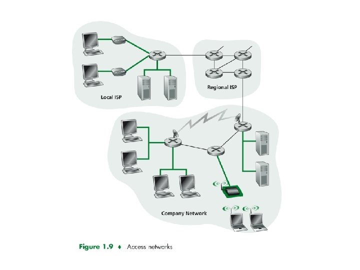
Access networks and physical media Q: How to connect end systems to edge router? residential access nets institutional access networks (school, company) mobile access networks Analog Modem Digital Modem Keep in mind: bandwidth (bits per second) of access network? shared or restricted? 38
Residential access: point to point access Dialup via modem Poor quality of twisted-pair line up to 56 Kbps direct access to router (often less) Can’t surf and phone at same time: can’t be “always on” ADSL: asymmetric digital subscriber line up to 1 Mbps upstream (today typically < 256 kbps) up to 8 Mbps downstream (today typically < 1 Mbps) DSL use FDM: 50 k. Hz - 1 MHz for downstream 4 k. Hz - 50 k. Hz for upstream 0 k. Hz - 4 k. Hz for ordinary telephone 39
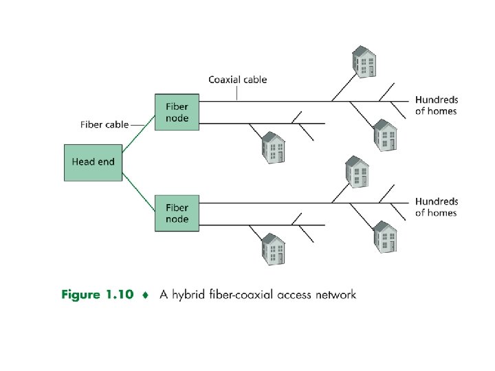
Residential access: cable modems HFC: hybrid fiber coax asymmetric: up to 30 Mbps downstream, 2 Mbps upstream Requires special modem called Cable Modems. HFC shared broadcast medium. 40
Company access: local area networks company/univ local area network (LAN) connects end system to edge router Ethernet: shared or dedicated link connects end system and router 10 Mbs, 100 Mbps, Gigabit Ethernet LANs: chapter 8 42
Wireless access networks shared wireless access network connects end system to router via base station ( wireless access point) wireless LANs: 802. 11 b (Wi. Fi): 11 Mbps Ch 8 wider-area wireless access provided by telco provider. Serves users within a radius of 10 Km. router base station mobile hosts 43
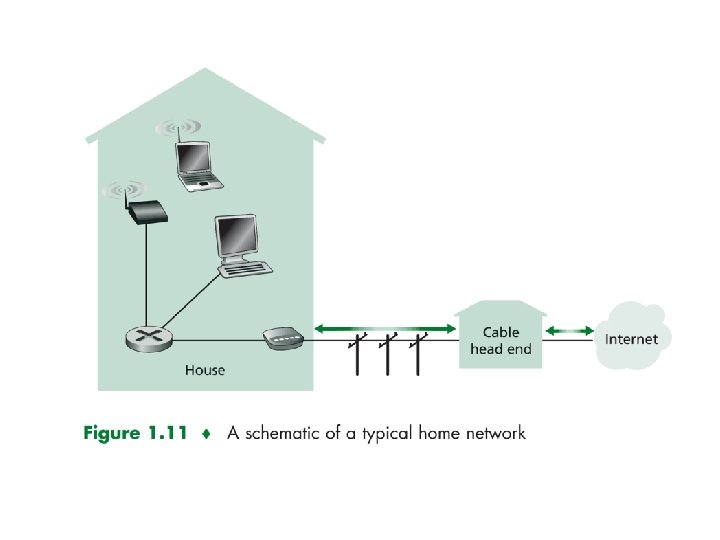
Home networks Typical home network components: ADSL or cable modem router/firewall/NAT Ethernet wireless access point to/from cable headend cable modem router/ firewall Ethernet wireless laptops wireless access point 45
Physical Media Bit: traveling from one end system to another.
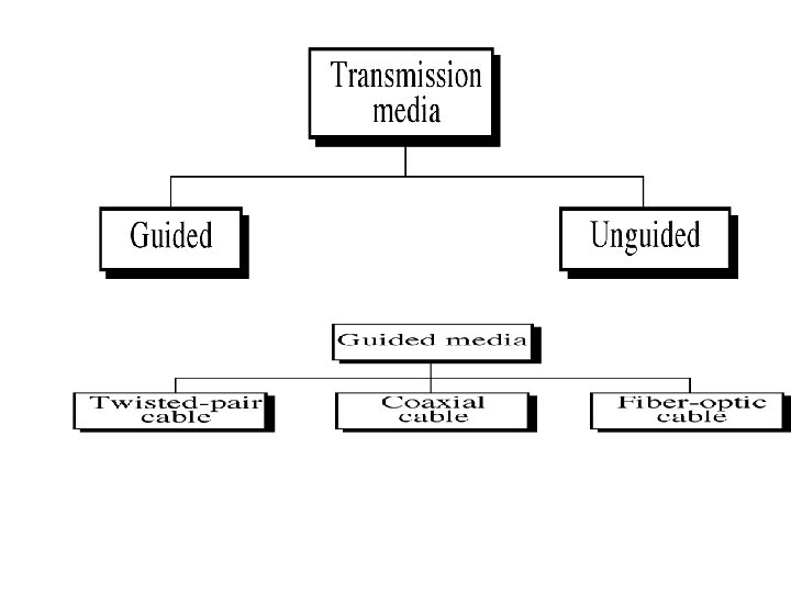
Physical Media Bit: propagates between transmitter/rcvr pairs physical link: what lies between transmitter & receiver guided media: signals propagate in solid media: copper, fiber, coax unguided media: signals propagate freely, e. g. , radio, wireless LAN 47
Twisted Pair (TP) two insulated copper wires Category 1: Less expensive and most commonly used Category 2 : traditional phone wires, 10 Mbps Ethernet Category 3: 100 Mbps Ethernet
Physical Media: coax, fiber Coaxial cable: two concentric copper conductors (not parallel) Ex: TV Cable bidirectional baseband: single channel on cable broadband: multiple channels on cable Fiber optic cable: glass fiber carrying light pulses, each pulse a bit high-speed operation: high-speed point-to-point transmission (e. g. , 10’s 100’s Gps) low error rate. Ex: Backbone of the Internet 50
Chapter 2: roadmap 2. 1 Network edge 2. 2 Network core 2. 3 Access Network and physical media 2. 4 Delay & loss in packet-switched networks 2. 5 Protocol layers, service models 51
How do loss and delay occur? packets queue in router buffers packet arrival rate to link exceeds output link capacity packets queue, wait for turn packet being transmitted (delay) A B packets queueing (delay) free (available) buffers: arriving packets dropped (loss) if no free buffers 52
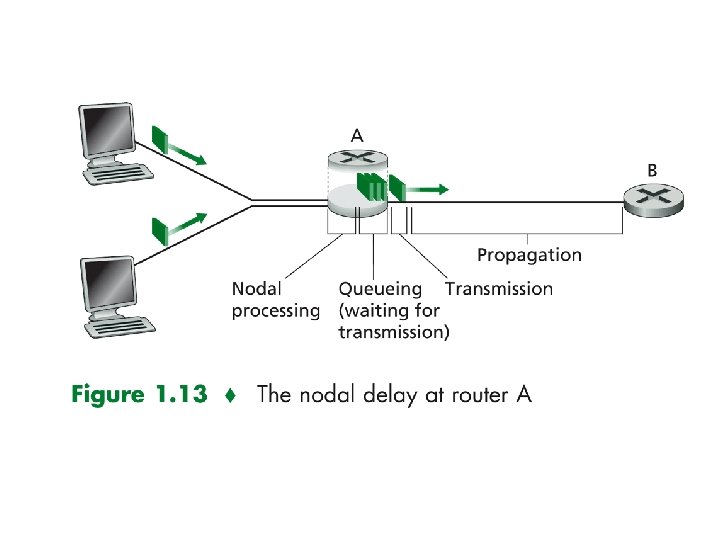
Four sources of packet delay 1. nodal processing: check bit errors: In transmitting the packet’s bit from upstream node to router determine output link 2. queueing time waiting at output link for transmission depends on congestion level of router transmission A propagation B nodal processing queueing 54
Delay in packet-switched networks 3. Transmission delay: R=link bandwidth (bps) L=packet length (bits) time to send bits into link = L/R transmission A 4. Propagation delay: d = length of physical link s = propagation speed in medium (~2 x 10⁸ m/sec) propagation delay = d/s Note: s and R are very different quantities! propagation B nodal processing queueing 55
Transmission and Propagation Delay Transmission Delay: is the amount of time required for router to push out the packet (Packet length, transmission rate). Propagation Delay: is time a bit takes to propagate from one router to the next (distance between two routers).
Caravan analogy 100 km ten-car caravan toll booth 100 km toll booth • Time to “push” entire • Cars “propagate” at caravan through toll 100 km/hr booth onto highway = • Toll booth takes 12 sec 12*10 = 120 sec to service a car • Time for last car to (transmission time) propagate from 1 st to • car~bit; caravan ~ 2 nd toll both: packet 100 km/(100 km/hr)= 1 • Q: How long until
Nodal delay (Total delay) dproc = processing delay typically a few microsecs or less dqueue = queuing delay depends on congestion dtrans = transmission delay = L/R, significant for low-speed links dprop = propagation delay a few microsecs to hundreds of msecs 58
Queueing delay (revisited) R=link bandwidth (bps) L=packet length (bits) a=average packet arrival rate traffic intensity = La/R ~ 0: average queueing delay small La/R -> 1: delays become large La/R > 1: more “work” arriving than can be serviced, average delay infinite! 59
“Real” Internet delays and routes What do “real” Internet delay & loss look like? Traceroute program: provides delay measurement from source to router along end-end Internet path towards destination. For all i: sends three packets that will reach router i on path towards destination router i will return packets to sender times interval between transmission and reply. 3 probes 60
“Real” Internet delays and routes traceroute: gaia. cs. umass. edu to www. eurecom. fr Three delay measurements from gaia. cs. umass. edu to cs-gw. cs. umass. edu 1 cs-gw (128. 119. 240. 254) 1 ms 2 border 1 -rt-fa 5 -1 -0. gw. umass. edu (128. 119. 3. 145) 1 ms 2 ms 3 cht-vbns. gw. umass. edu (128. 119. 3. 130) 6 ms 5 ms 4 jn 1 -at 1 -0 -0 -19. wor. vbns. net (204. 147. 132. 129) 16 ms 11 ms 13 ms 5 jn 1 -so 7 -0 -0 -0. wae. vbns. net (204. 147. 136) 21 ms 18 ms 6 abilene-vbns. abilene. ucaid. edu (198. 32. 11. 9) 22 ms 18 ms 22 ms 7 nycm-wash. abilene. ucaid. edu (198. 32. 8. 46) 22 ms trans-oceanic 8 62. 40. 103. 253 (62. 40. 103. 253) 104 ms 109 ms 106 ms link 9 de 2 -1. de. geant. net (62. 40. 96. 129) 109 ms 102 ms 104 ms 10 de. fr 1. fr. geant. net (62. 40. 96. 50) 113 ms 121 ms 114 ms 11 renater-gw. fr 1. fr. geant. net (62. 40. 103. 54) 112 ms 114 ms 112 ms 12 nio-n 2. cssi. renater. fr (193. 51. 206. 13) 111 ms 114 ms 116 ms 13 nice. cssi. renater. fr (195. 220. 98. 102) 123 ms 125 ms 124 ms 14 r 3 t 2 -nice. cssi. renater. fr (195. 220. 98. 110) 126 ms 124 ms 15 eurecom-valbonne. r 3 t 2. ft. net (193. 48. 50. 54) 135 ms 128 ms 133 ms 16 194. 211. 25 (194. 211. 25) 126 ms 128 ms 126 ms 17 * * means no response (probe lost, router not replying) 18 * * * 19 fantasia. eurecom. fr (193. 55. 113. 142) 132 ms 128 ms 136 ms 61
Packet loss queue (aka buffer) preceding link in buffer has finite capacity when packet arrives to full queue, packet is dropped (aka lost) lost packet may be retransmitted by previous node, by source end system, or not retransmitted at all 62
Chapter 2: roadmap 2. 1 Network edge 2. 2 Network core 2. 3 Access Network and physical media 2. 4 Delay & loss in packet-switched networks 2. 5 Protocol layers, service models 63
What’s a protocol? a human protocol and a computer network protocol: Hi TCP connection request Hi TCP connection response Got the time? Get http: //www. awl. com/kurose-ross 2: 00 <file> time Q: Other human protocols? 64
Protocol “Layers” Networks are complex! many “pieces”: hosts routers links of various media applications protocols hardware, software Question: Is there any hope of organizing structure of network? Or at least our discussion of networks? 65
Organization of air travel ticket (purchase) ticket (complain) baggage (check) baggage (claim) gates (load) gates (unload) runway takeoff runway landing airplane routing a series of steps 66
Layering of airline functionality ticket (purchase) ticket (complain) ticket baggage (check) baggage (claim baggage gates (load) gates (unload) gate runway (takeoff) runway (land) takeoff/landing airplane routing departure airport airplane routing intermediate air-traffic control centers arrival airport Layers: each layer implements a service via its own internal-layer actions relying on services provided by layer below 67
Why layering? Dealing with complex systems: explicit structure allows identification, relationship of complex system’s pieces layered reference model for discussion modularization eases maintenance, updating of system change of implementation of layer’s service transparent to rest of system e. g. , change in gate procedure doesn’t affect rest of system layering considered harmful? 68
Internet protocol stack application: supporting network applications FTP, SMTP, HTTP transport: host-host data transfer TCP, UDP network: routing of datagrams from source to destination IP, routing protocols link: data transfer between neighboring network elements application transport network link physical PPP, Ethernet physical: bits “on the wire” 69
source message segment Ht datagram Hn Ht frame Hl Hn Ht M M Encapsulation application transport network link physical Hl Hn Ht M switch destination M Ht M Hn Ht Hl Hn Ht M M application transport network link physical Hn Ht Hl Hn Ht M M router 70