Chapter 2 CANNED CYCLES AND SUBROUTINES CANNED CYCLES

Chapter 2 CANNED CYCLES AND SUBROUTINES

CANNED CYCLES "Canned" ? The word "canned" has probably been borrowed from canned goods, which one usually stores away for later use.

CANNED CYCLES "Cycle" ? Because the instructions represented a set of routine like repetitive patterns.

Canned cycles & G-code address These canned cycles are filed away under a standardized G-code address G 84 G 81 G 82 G 83 G 76 G 84 G 85 G 86

Types of canned cycles 1 -Milling and Drilling Canned cycles 2 - Turning Canned cycles

Usually, in one tape block, the canned cycle will control all or most of the following motions: • Positioning the tool in the X-Y plane • Rapid motion to the "R" level, Rapid Down To • Controlled feed motion to the "Z" level, • Commanded motions at "Z" level, such as dwell, spindle stop, spindle reverse, spindle orientation, spindle lateral shift, etc. , • Rapid or feed return to "R" level, as applicable, and • Rapid return to INITIAL level.

Tapping canned cycles Consist of the following steps: • Clockwise rotating of the tap at the correct rpm • Rapid advancing of the tap to (R-level)- Rapid Down To • Feeding the rotating tap to a set depth at a rate of one thread pitch per revolution (or mm/rev, or in in. /rev. ) • Reversing both feed and spindle rotation • Feeding the rotating tap until the tap reaches the R-Level • Returning spindle rotation to its original clockwise direction The spindle is now ready to rapidly return "home" for a tool change, relocate to another position or carry out any other instruction of the program. Similar motion patterns are available for drilling, boring, turning, threading, etc.

General format of the fixed Milling canned cycle is the following: N G G X Y Z R Q P F L N is the sequence number of the block G is the respective canned cycle (e. g. , G 81, G 84, G 73, G 76, etc. ) The second G may be G 98 or G 99. G 98 will return the tool point to the initial level. ( Save Rapid Level) G 99 will return the tool point to R level; X and Y are the coordinates of the location to be machined

Z is the level attained by the tool in feed mode R is the level reached by the tool at the end of its rapid motion Q is the depth of cut in feed in peck drilling P is the dwell in spot facing or boring operations F is the feed L is the number of repeats, if applicable

The following observations apply to canned cycles for machining centers in general: • The tool motion starts in canned cycle from an Initial Level. • The tool will move in Rapid mode to the programmed X-Y location • The quill will move in Rapid mode to the R (for Rapid) Level. • The tool will feed to the Z-Level, Z-Level is measured from Initial in absolute mode (G 90) Z-Level is measured from R in incremental mode (G 91).

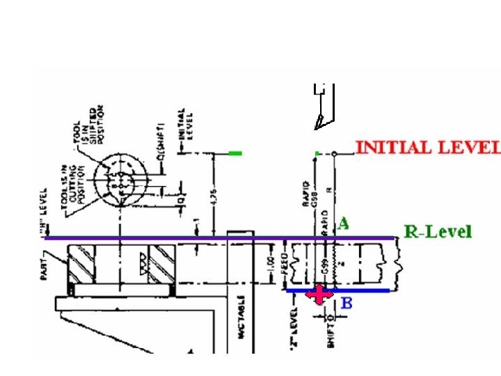
Three levels of tool position in any canned cycle: • The Initial level, which is the specific position of the tool at the moment the canned cycle becomes effective, • The "R" for Rapid level, which is the end of the rapid quill motion, usually 0. 020 to 0. 100 inches (0. 5 to 2. 5 mm) from the part surface, and • The "Z" level which is the end of the feed (metal cutting) motion.

• If the tool is already on location, there is no need to program X and. Y. • A canned cycle is in effect until canceled (or replaced by another canned cycle). Accordingly, subsequent locations can be machined by simply programming X and Y in subsequent blocks. • If you do not intend to perform the canned cycle at the next location, you must cancel it first (G 80).
 Z-Level is measured")
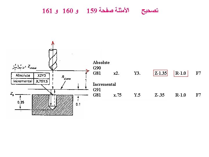
Z-Level is measured from Initial- Level in absolute mode (G 90) Z-Level is measured from R- Level in incremental mode (G 91). Absolute Incremental

• Cutter Compensation. . . . No. Since X-Y motions are strictly for positioning and the programmed machining patterns take place in the Z-axis, no canned cycles are to be used in cutter diameter compensation mode. • Canned Cycles for all systems are standard. . . . No. Most systems provide numerous canned cycles as standard equipment, but not all systems use the same codes to designate the same cycles. Always use the codes provided by your system manual.

Drilling Canned Cycle G 81: G 81 Is a canned cycle for drilling holes in a single drill stroke. Its motion is rapid motion to R plane, feed down (into the hole) and rapid up (out of the hole) to the R level or to the initial Z level (Zinitial) G 81 Xn Yn Zn Rn Fn

Counter boring or countersinking holes cycle G 82: G 82 Xn Yn Zn Rn Fn Pn Its action is similar to G 81, except that it has a timed dwell at the bottom of the Z-stroke. Will spot face, bore, or counter bore. The canned cycle will perform as follows: Rapid to "R" , Feed to "Z, " Dwell at "Z" for a duration given by "P" Rapid return to "R" or Initial depending on whether G 99 or G 98 was called in the program. One second is P 100 and 3 seconds are P 300,

Counter boring or countersinking holes cycle G 82: G 82 Xn Yn Zn Rn Fn Pn Rapid to "R" , Feed to "Z, " Dwell at "Z" for a duration given by "P" Rapid return to "R" or Initial depending on whether G 99 or G 98 was called in the program. One second is P 100 and 3 seconds are P 300,

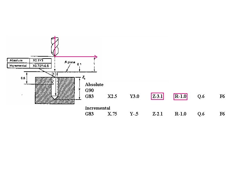
Deep drilling canned cycle G 83 : • Hole depth > 3 times the drill's diameter. • Prevent chips from packing in the drill's flutes, resulting in drill breakage. G 83 Xn Yn Zn Qn Rn Fn

Deep drilling canned cycle G 83 : • Drill in at feed rate a small distance (called the peck ﻧﻘﺮ increment) and then retract at rapid travel. • Then the drill advances at rapid travel back down to its previous depth, feeds in another peck increment, and rapids back out again. • Then it rapids back in, feeds in another peck increment, etc. , until the final Z-depth is achieved. G 83 Xn Yn Zn Qn Rn Fn

Deep drilling canned cycle G 83 :

G 83 will: G 83 Xn Yn Zn Qn Rn Fn 1. Rapid to X-Y location and to "R" level, 2. Feed by the amount "Q" 3. Rapid return to "R" 4. Rapid in by "Q-d, " 5. Feed "Q" from there, 6. Rapid return to "R" thus removing the swarf from the part, 7. Rapid in by "2 Q-2 d" 8. Feed "Q" from there, 9. Rapid return to "R" etc.

The G 84 The programmed feed must be fully synchronized with the spindle speed Before starting the tapping portion of the program, we have to set tapping speeds and calculate tapping feeds.

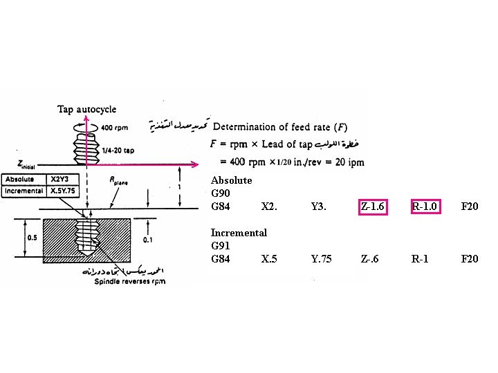
G 84 Is a canned cycle for tapping. It coordinates the spindle's rotary motion to the Z-axis motion for feeding the tap into and out of the hole without breaking off the tap. G 84 Xn Yn Zn Rn Fn G 81 Xn Yn Zn Rn Fn

G 84 Xn Yn Zn Rn Fn The G 84 canned cycle will perform the tapping of one or more holes as follows: Rapid to "R" level, Feed to "Z-" level, Reverse direction of rotation at "Z-" level, Feed up to "R" level, Reverse direction of rotation to original direction.
, What")
Suppose the tapping speed has been selected to be 100 rpm (S 100), What is the tapping feed (ipm) for 3/8 "-16 ? 1. Calculate the pitch in inch: Sixteen tpi represent a pitch of 1/16 or 0. 0625 inch. 2 -Find the feed per rev: Feed / rev = Pitch in inches =0. 0625 inch/ rev. 3 - Calculate the feed per minute Feed per minute = feed per rev * Speed (rpm) 100 x 0. 0625 = 6. 25 ipm, ( F 6. 25 ) Short Formula: Divide the selected speed by the number of tpi. Therefore, 100/16 = 6. 25 and we program F 6. 25.

Using an "inch" tap in a metric program Multiplying 6. 25 ipm by the factor 25. 4 = F 158. 75 mm/min.

Metric threads in a metric program M 6 x l , Using 125 rpm F. . . mm/min. ? We just multiply the pitch by the selected rpm Feed will be 1 X 125 = 125 F 125.

Metric threads in an inch program F 125 mm/min =. . . . inc/min. We simply divide the feed obtained by 25. 4. Hence, 125 (mm/min) / 25. 4 will be programmed as F 4. 9213 ipm

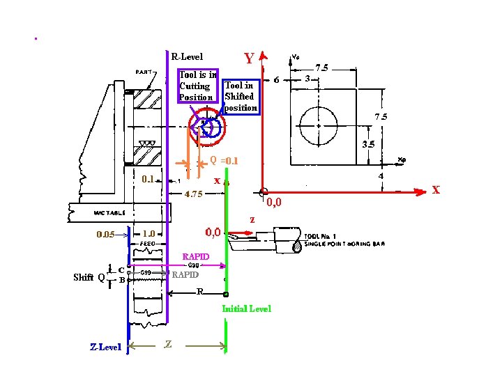
Fine boring canned cycle G 76 Xn Yn Zn Rn Qn Fn 1 - Rapid to "R" (point A). 2 - Feed to "Z" (point B), 3 - Spindle stop 4 - Orient, shift the tool point by the programmed amount Q away from the hole wall, 5 - Rapid return to "R" or Initial as programmed 6 -Restart of spindle.

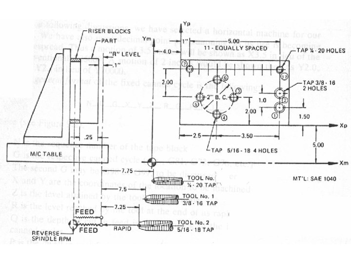
Example: Write the program to bore the hole in the following part in absolute

Example: Write the program to bore the hole in the following part in absolute

N 0010 G 20 G 40 G 80 G 90 G 00 G 20: (Inch programming, shown above as G 20, is programmed on many controls as G 70. Check your programming manual. ) G 40: Cancel Radius Compensation G 80: Cancel previous canned cycle N 0020 T 01 M 06 N 0030 G 92 X 0 Y 0 Z 0 This command will zero the registers with no motion taking place N 0040 S 600 M 03 - Spindle On N 0050 M 08 - Coolant On N 0060 G 98 G 76 X 9. 0 Y 7. 5 Z-5. 9 R-4. 75 Q 0. 1 F 0. 75

: ﺳﺆﺎﻝ How many ridges will be remains on the hole after executing the above CNC program (600 rpm, F 0. 75 inch/min) ? : ﻻﺟﺎﺑﺔ ﺍ At 600 rpm, F 0. 75 inch/min will ensure 800 tool marks or ridges in 1 inch of bored surface. How? Feed per rev = 0. 75 ÷ 600 = 0. 00125 inch per rev = Ridge Thickness Number of Ridges in 1 inch = 1 ÷ 0. 00125 = 800
 : ﺍﻻﺟﺎﺑﺔ")
: ﺳﺆﺎﻝ How to produce finer surface ( Increase Number of Ridges) : ﺍﻻﺟﺎﺑﺔ Feed per rev = Feed per min ÷ Speed=. . . . inch per rev = Ridge Thickness Number of Ridges in 1 inch = 1 ÷Ridge Thickness =. . . Should a finer surface be required, we can increase S, reduce F, or both. In a production situation, a carbide-tipped boring tool could run at speeds to 3, 000 rpm and feeds to 3. 5 ipm.
 any of the G 80 -series canned")
Canned cycle cancellation G 80 deactivates (cancels) any of the G 80 -series canned Z-axis cycles. Each of these canned cycles is modal. Once put in effect, a hole will be drilled, bored, or tapped, each time the spindle is moved to a new location. This code is normally used in three situations:

1 -When different programs are run consecutively on the same machine, it issued before the first motion statement, in conjunction with other codes as a safety feature, to cancel potential leftover canned cycles from a previous program. On some controls, a previously used canned cycle may remain active even if the control is reset or the power is turned off. N 0010 G 20 G 40 G 80 G 49 G 91 G 00

2 -When a canned cycle is canceled, as it should be, as soon as it is no longer needed in the program. N 0040 G 80 3 -When it is required to reposition the spindle without any machining taking place at that location (such as an intermediary position in a change of direction). N 0090 G 80 X 3. 0 Y 4. 5

Z n , Rn

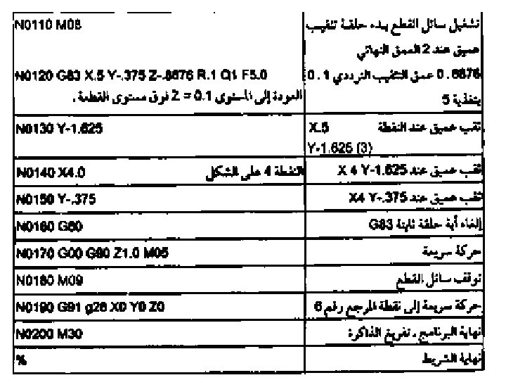
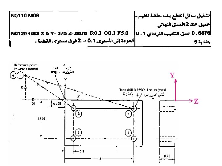
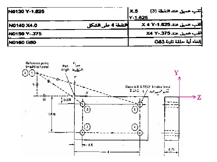
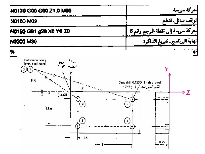
Write a CNC program to perform the drilling operation in the following figure, use the data in the table
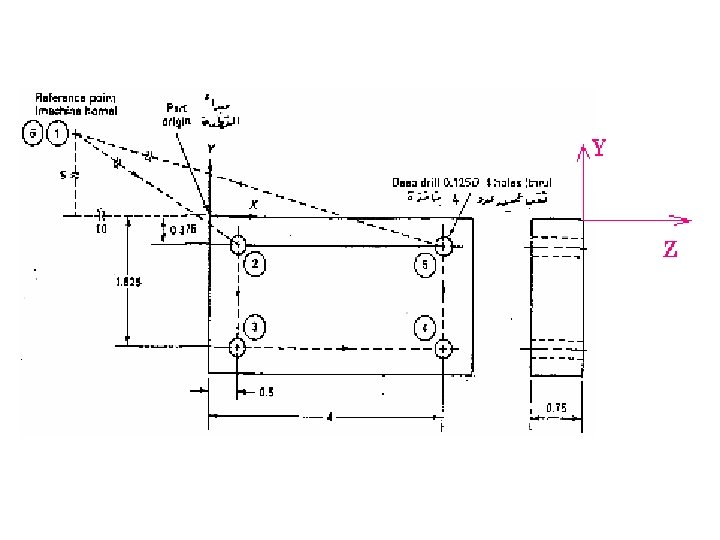

0. 0376 +0. 1000 +0. 7500 = 0. 8876

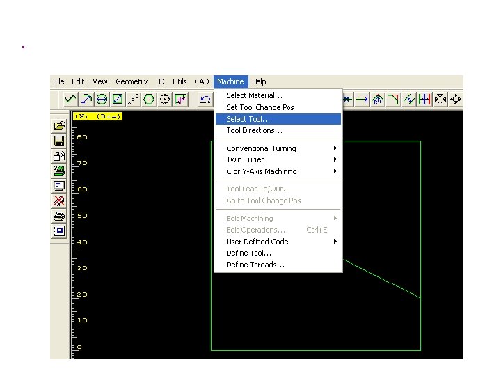
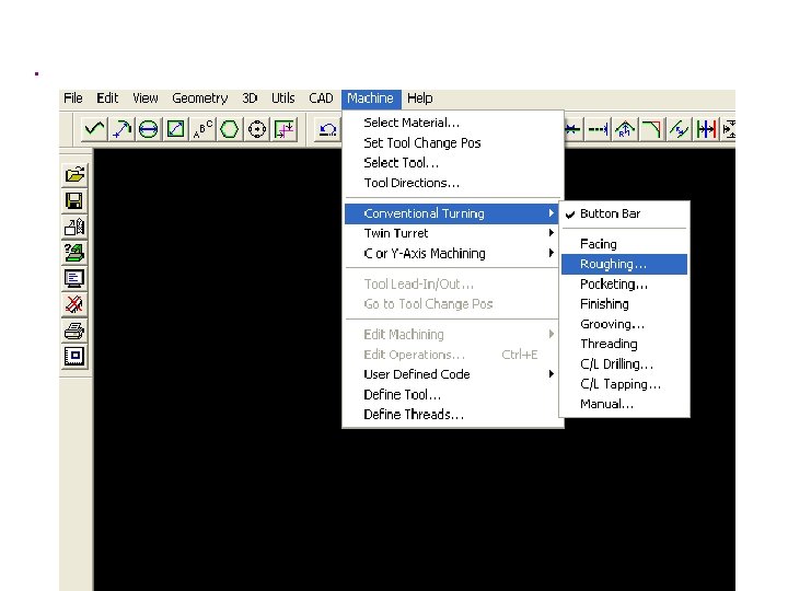
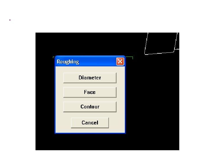
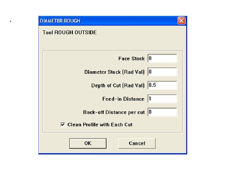
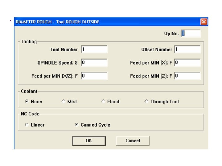
Turning Canned cycles Longitudinal turning cycle G 84 A G 0 command is used to bring the tip of the tool to starting position S.

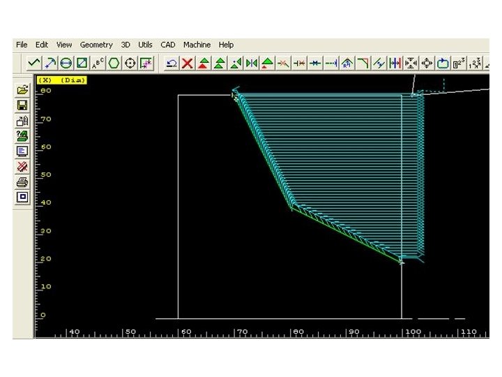
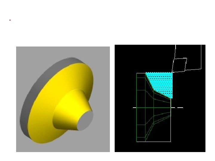
The G 84 command will make the tool move in a series of rectangular paths cutting material axially until the tool tip reaches target point K where the cycle ends. Cutting movements will be at the cutting feed rate. All other movements will be at rapid traverse rate.

N G 84 X, Z Po P 2 Do D 2 D 3 F Block Number Longitudinal Turning Cycle Absolute, Incremental Coordinates of the contour joint point K Taper dimension in X Direction Taper dimension in Z Direction Allowance in X Allowance in Z Cut division Feed

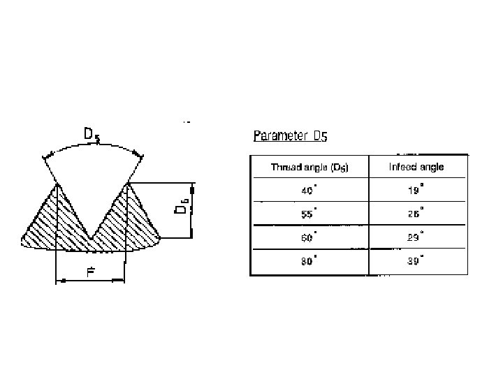
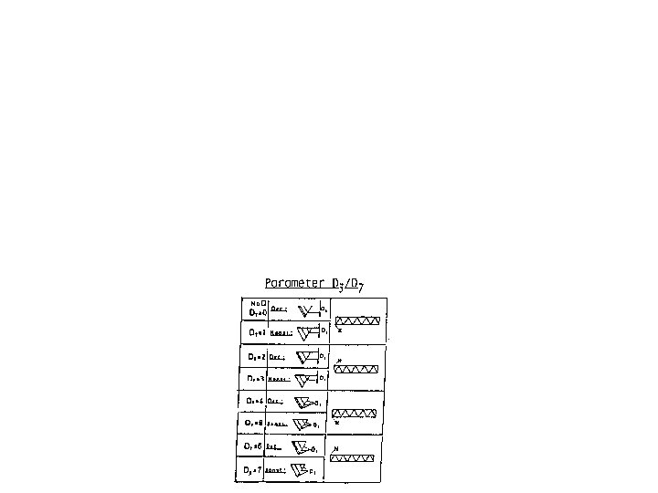
N G 85 X, Z P 2 D 3 D 4 D 5 D 6 D 7 F Block Number Threading Cycle Absolute, Incremental Coordinates of the thread end point K or N Thread run out Depth or Number ( From Table) Number of no load cuts to clean Angle of thread Total thread depth Identification number (from table) Feed

Plunge – cut cycle G 86 A G 0 command brings the right-hand corner of the tool to starting position P. The G 86 command will make the tool move forward, back and left repeatedly to cut the groove. The movements continue until the left-hand corner of the tool tip reaches target point K where the cycle ends.

N G 86 X, Z D 3 D 4 D 5 F Block Number Plung Cut Cycle Absolute, Incremental Coordinates of the contour joint point K Feed per Cut ( feed /rev) Dwell time Tool width Feed

G 25 Subroutine Call Canned cycles could be made even more efficient by the use of the Subroutine feature, when sevral operations (center drill, booring, tap, etc. ) are performed at the same location. The location pattern is placed in a Subprogram known as Subroutine and called as needed by the main program

Write a program for milling the shown 4 rectangular pockets in the shown part, use G 25 subroutine call to facilitate your programming.

N 10 G 90 S 800 M 03 N 20 G 00 X 20 Y 12. 5 N 30 G 01 Z 0. 1 F 55 M 08 N 40 G 25 L 200 01 N 50 G 00 X 65 N 40 G 25 L 200 01 N 50 G 00 X 110 N 40 G 25 L 200 01 N 50 G 00 X 155 N 40 G 25 L 200 01 N 50………………… N 60………………… N 70………………… N 80………………… N 90………………… N 100 M 30 O 200 N 510 N 520 N 530 N 540 N 550 N 560 N 570 N 580 G 92 G 42 G 01 X 25 Y 0 X 0 G 00 M 17 X 0 G 90 Z-5 Y 25 Z 0. 1 Y 0 F 2. 5 F 5


% 021102 N 000 G 71 N 010 G 00 X 35 Z 141 T 0101 S 700 N 020 G 84 X 24 Z 95 P 0=0. 0 P 2=0. 0 D 3=500 F 100 N 030 G 01 X 24 Z 140 F 50 N 040 G 84 X 15 Z 115 D 3=500 F 100 N 050 G 00 X 15 Z 141 N 060 G 84 X 0. 0 Z 140 N 070 G 00 X 40 Z 150 M 04 P 2= -15 D 3=500 F 100

N 080 G 00 X 25 Z 100 T 0202 N 090 G 86 X 15 Z 95 D 3=100 D 4=1 N 100 G 00 X 40 Z 150 N 110 G 00 X 25 Z 98 N 120 X 24 Z 115 F 1500 X 40 Z 150 P 2=2 N 130 G 85 D 7=7 G 00 N 140 G 00 X 24 Z 95 T 0101 N 150 G 02 X 34 Z 90 I 5 N 160 G 00 X 40 Z 156 N 170 M 30 D 5=4000 F 50 T 0404 S 300 D 3=6 D 4=2 D 5=80 D 6=1200 K 0 F 50 S 500
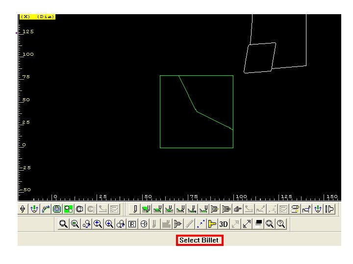

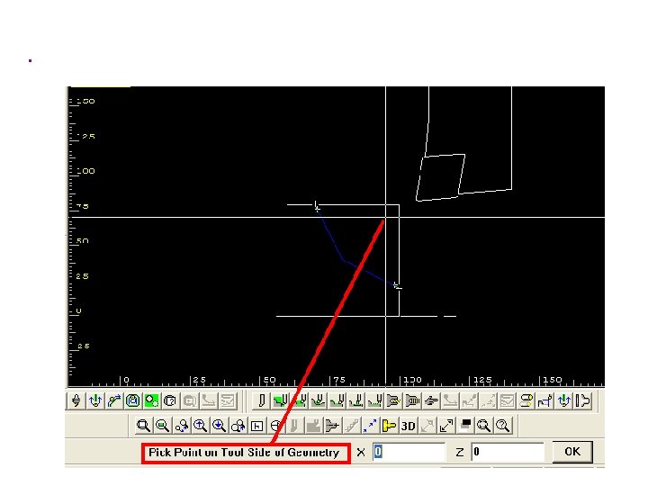
Select a point a little amount far from the begining to avoid error message

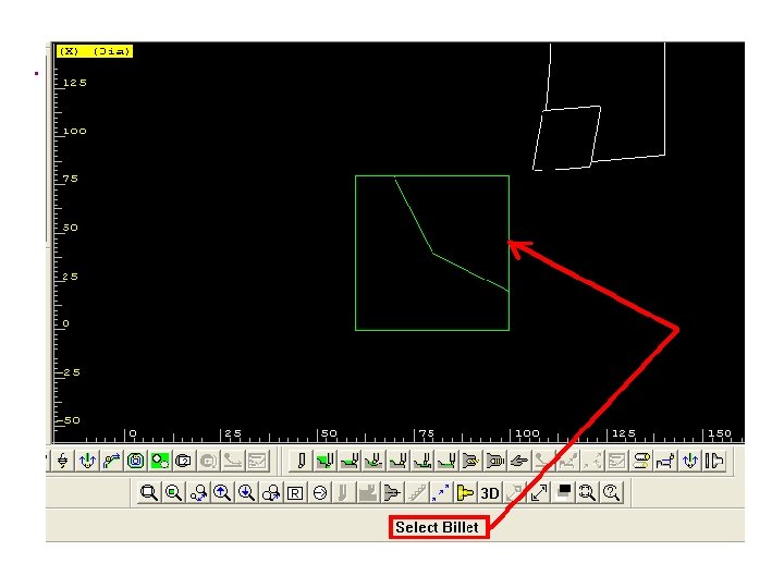
Select a point a little amount far from the end to avoid error message
- Slides: 86