CHAPTER 2 Amplitude Modulation AM RECEIVERS 1 Introduction


")


 between the minimum input level")


 Te = T(F-1) Where T = environmental temperature (kelvin)")


 block diagram EKT 231 EMT 231 Communication")

")


 n n n Mixers generate signals that are the sum and")
 is an undesired signal that is separated")


 Identify the information IF=455 k. Hz RF=600 k. Hz LO= 1055")
 (ii) IFRR for a preselector Q of 200 EKT 231 EMT")

 f. LO = f. RF + f. IF = 27")
 For the same IFRR, the high RF freq. is required")

 -High side injection -RF = 25 MHz -IF = 425 k.")
 iii) IFRR for a preselector Q of 150 iv) Preselector Q")


- Slides: 45
CHAPTER 2 Amplitude Modulation AM RECEIVERS 1
Introduction n AM demodulation – reverse process of AM modulation. Demodulator: converts a received modulatedwave back to the original source information. Basic understanding of the terminology commonly used to describe radio receivers & their characteristics is needed to understand demodulation process EKT 231 Communication System 2
Simplified block diagram of an AM receiver IF- intermediate frequency, which are simply frequencies that fall somewhere between the RF & information Frequencies Functions-amplification & selectivity Receiver front end Function-detecting, bandlimiting & amplifiying Demodulates the AM wave and converts it to original information signal EKT 231 EMT 231 Communication System Principles 3 Recovered information
Receiver Parameters n n n n Selectivity Bandwidth improvement Sensitivity Dynamic range Fidelity Insertion Loss Noise temperature & Equivalent noise temperature EKT 231 EMT 231 Communication System Principles 4
Selectivity n n n Used to measure the ability of the receiver to accept a given band of frequencies and reject all others. Way to describe selectivity is to simply give the bandwidth of the receiver at the -3 d. B points. Not necessarily a good means of determining how well the receiver will reject unwanted frequencies. EKT 231 EMT 231 Communication System Principles 5
Cont’d… n n Give the receiver bandwidth at two levels of attenuation. Eg: -3 d. B, -60 d. B The ratio of two BW ~ Shape factor SF = B(-60 d. B) / B(- 3 d. B) Where SF – Shape factor B(-60 d. B) – BW 60 d. B below max signal level B(-3 d. B) – BW 3 d. B below max signal level EKT 231 EMT 231 Communication System Principles 6
Cont’d… n n n If both BW equal, the shape factor would be 1. Impossible to achieve in practical circuit Example application for SF nearly 1 n n n Satellite Microwave Two way radio Rx EKT 231 EMT 231 Communication System Principles 7
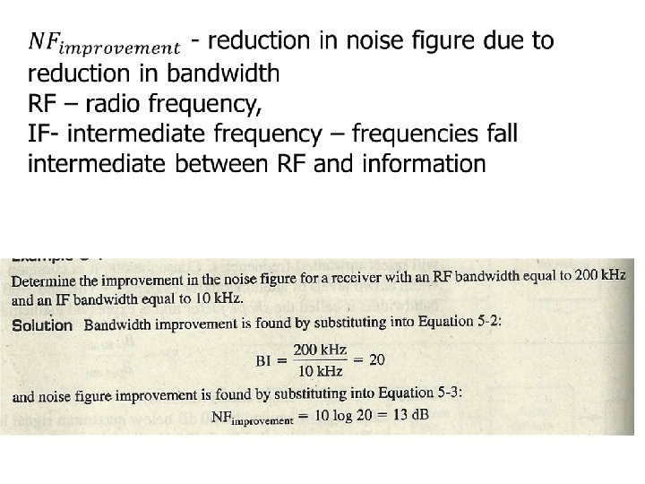
Bandwidth Improvement n n n Thermal noise directly proportional to bandwidth. Reduce BW ~ reduce noise, improving system performance. Reducing BW = improving the noise figure of the RX EKT 231 EMT 231 Communication System Principles 8
Cont’d… Bandwidth Improvement, BI BI = BRF /BIF Where BRF = RF Bandwidth (Hz) BIF = IF Bandwidth (Hz) Noise figure improvement, NFimprovement = 10 log BI EKT 231 EMT 231 Communication System Principles 9
Sensitivity n n n The minimum RF signal level that can be detected at the input to the Rx and still produce a usable demodulated information signal. Usually stated in micro volts of received signal. Rx sensitivity also called Rx threshold. EKT 231 EMT 231 Communication System Principles 11
Cont’d… n Depends on: n n n The noise power present at the input to the Rx. Rx noise figure. AM detector sensitivity. BI factor of the Rx To improve ~ reduce the noise level n n Reducing the temperature or Rx BW Improving the RX noise figure EKT 231 EMT 231 Communication System Principles 12
Dynamic range n n The difference (in d. B) between the minimum input level necessary to discern a signal and the input level that will overdrive the Rx and produce distortion. Input power range over which the Rx is useful. EKT 231 EMT 231 Communication System Principles 13
Cont’d… n n A dynamic range of 100 d. B is considered about the highest possible. A low dynamic range can cause a desensitizing of the RF amplifiers and result in severe intermodulation distortion of the weaker input signal. EKT 231 EMT 231 Communication System Principles 14
Fidelity n A measure of the ability of a communication system to produce (at the output of the Rx) an exact replica of the original source information. EKT 231 EMT 231 Communication System Principles 15
Cont’d… n Forms of distortion that can deteriorate the fidelity of a communication system: n n n Amplitude Frequency Phase EKT 231 EMT 231 Communication System Principles 16
Insertion loss n n IL is a parameter associated with the frequencies that fall within the passband of a filter. The ratio of the power transferred to a load with a filter in the circuit to the power transferred to a load without the filter. IL (d. B) = 10 log (Pout /Pin) EKT 231 EMT 231 Communication System Principles 17
Noise Temperature & Equivalent noise Temperature Thermal noise directly proportional to temperature ~ can be expressed in degrees, watts or volts. n Environmental temperature, T (kelvin) T = N/KB Where N = noise power (watts) K = Boltzman’s Constant (1. 38 X 10 -23 J/K) B = Bandwidth (Hz) n EKT 231 EMT 231 Communication System Principles 18
Cont’d… Equivalent noise temperature, (Te) Te = T(F-1) Where T = environmental temperature (kelvin) F = Noise factor n Te often used in low noise, sophisticated radio receivers rather than noise figure. n EKT 231 EMT 231 Communication System Principles 19
AM RECEIVERS n 1. Two basic types of radio receivers. Coherent n n 2. Synchronous receivers The frequencies generated in the Rx & used for demodulation are synchronized to oscillator frequencies generated in Tx. Non-coherent n n n Asynchronous receivers Either no frequencies are generated in the Rx or the frequencies used for demodulation completely independent from the Tx’s carrier frequency. Non-coherent detection = envelope detection. EKT 231 EMT 231 Communication System Principles 20
COHERENT n EXAMPLE OF COHERENT DEMODULATION: SSB Ø The received signal is heterodyned /mixed with a local carrier signal which is synchronous (coherent) with the carrier used at the transmitting end. Coherent demodulation SSB X LPF cos wct EKT 231 EMT 231 Communication System Principles 21
Non-Coherent Rx n n Tuned Radio Frequency Rx Superheterodyne Rx EKT 231 EMT 231 Communication System Principles 22
Non-coherent tuned radio frequency receiver (TRF Rx) block diagram EKT 231 EMT 231 Communication System Principles 23
Cont’d… n n n Earliest types of AM Rx. Figure shows the block diagram of a three stage TRF Rx. Consists of RF stage, detector stage and audio stage. Simple and high sensitivity. BW inconsistent & varies with the center frequency. EKT 231 EMT 231 Communication System Principles 24
Cont’d… n Skin effect phenomenon. Skin effect is a tendency for alternating current (AC) to flow mostly near the outer surface of an electrical conductor, such as metal wire. The effect becomes more and more apparent as the frequency increases. . B = f/Q Where Q is quality factor. n TRF Rx is useful to single-channel, low frequency application. n EKT 231 EMT 231 Communication System Principles 25
Example
AM superheterodyne receiver block diagram EKT 231 EMT 231 Communication System Principles 27
Cont’d… n n Non uniform selectivity of TRF led to the development of the Superheterodyne Rx. Its gain, selectivity and sensitivity characteristics are superior to those of other Rx configurations. EKT 231 EMT 231 Communication System Principles 28
Cont’d… Frequency conversion. High side injection, flo = f. RF + f. IF Low side injection flo = f. RF - f. If n EKT 231 EMT 231 Communication System Principles 29
Superheterodyne receiver RF-to-IF conversion f. RF f. LO f. IF High side injection f. IF=f. LO-f. RF f. IF EKT 231 EMT 231 Communication System Principles (f. LO=f. RF+f. IF) 30
INTERMEDIATE FREQUENCY (IF) n n n Mixers generate signals that are the sum and difference of the incoming signal frequency (f. IF) and the frequency of the local oscillator (f. LO). The difference frequency is more commonly chosen as the IF. Some receivers use the sum frequency for the IF. EKT 231 EMT 231 Communication System Principles 31
IMAGES n n An image (f. IM) is an undesired signal that is separated from the desired signal frequency (f. RF) by two times the IF (f. IF). f. IM = f. RF + 2 f. IF or f. RF - 2 f. IF Images interfere with the desired signal. Images can be eliminated or minimized by: n Proper selection of the IF in design. n Use of highly selective filters before the mixer. n Use of a dual conversion receiver. EKT 231 EMT 231 Communication System Principles 32
con’t’d… Image frequency fim = f. RF + 2 f. IF n Image Frequency rejection ratio IFRR = √ (1 + Q²ρ²) Where ρ = (fim/f. RF) –(f. RF/fim) n EKT 231 EMT 231 Communication System Principles 33
Example 1 For an AM broadcast-band superheterodyne receiver with IF, RF and local oscillator frequencies of 455 k. Hz, 600 k. Hz, and 1055 k. Hz, respectively, determine: i) Image frequency ii) IFRR for a preselector Q of 200 (*for High side injection) EKT 231 EMT 231 Communication System Principles 34
Example 1 (Solution) Identify the information IF=455 k. Hz RF=600 k. Hz LO= 1055 k. Hz i) Image frequency fim = f. RF + 2 f. IF = 600 k + 2(455 k) = 1510 k. Hz = f. LO + f. IF = 1055 k + 455 k = 1510 k. Hz EKT 231 EMT 231 Communication System Principles 35
Example 1 (Solution) (ii) IFRR for a preselector Q of 200 EKT 231 EMT 231 Communication System Principles 36
Example 1. 1 If RF = 27 MHz, IF 455 k. Hz Calculate Q to achieve the same IFRR with Example 1 EKT 231 EMT 231 Communication System Principles 37
Example 1. 1 (Solution) f. LO = f. RF + f. IF = 27 M + 445 k=27. 455 MHz fim = f. LO+fif=27. 455 M + 455 k=27. 91 M EKT 231 EMT 231 Communication System Principles 38
Example 1. 1 (Solution) For the same IFRR, the high RF freq. is required a much higher Q quality pre selector filter, thus unrealistic to realize for high Q Solution: Use high IF frequency when receiving higher RF EKT 231 EMT 231 Communication System Principles 39
Example 2 For a citizens band receiver using high-side injection with an RF carrier at 25 MHz and an IF center frequency at 425 k. Hz, determine: i) iii) iv) Locol oscillator frequency Image frequency IFRR for a preselector Q of 150 Preselector Q required to achieve the IFRR of 422 for an RF carrier of 500 k. Hz. EKT 231 EMT 231 Communication System Principles 40
Example 2 (Solution) -High side injection -RF = 25 MHz -IF = 425 k. Hz (i)Locol oscillator frequency flo = f. RF + f. IF = 25 M + 425 k = 25. 425 MHz (ii)Image frequency fim = f. RF + 2 f. IF =25 M + 2(425 k) =25. 85 MHz EKT 231 EMT 231 Communication System Principles 41
Example 2 (Solution) iii) IFRR for a preselector Q of 150 iv) Preselector Q required to achieve the IFRR of 422 for an RF carrier of 500 k. Hz. EKT 231 EMT 231 Communication System Principles 42
AM APPLICATION n AM Radio broadcasting n n Commercial AM radio broadcasting utilizes the frequency band 535 – 1605 k. Hz for transmission voice and music. Carrier frequency allocation range, 5401600 k. Hz with 10 k. Hz spacing. EKT 231 EMT 231 Communication System Principles 43
Cont’d… n n n Radio stations employ conventional AM for signal transmission – to reduce the cost of implementing the Rx. Used superheterodyne Rx. Every AM radio signal is converted to a common IF frequency of f. IF = 455 k. Hz. EKT 231 EMT 231 Communication System Principles 44
CHAP 2 SUMMARY 1. 2. 3. 4. 5. 6. 7. 8. Understand the AM Envelope How to calculate BW, modulation index, percentage of modulation Understand the Mathematical representation and analysis of AM (upper/lower frequencies, peak of modulated carrier, max/min amplitudes of the envelope, expression of modulated wave) Power distribution, frequency spectrum The difference between DSB & SSB Block diagram of SSB Transmitter Receiver parameters How to calculate the f. LO, f. IM, IFRR EKT 231 EMT 231 Communication System Principles 45