
Chapter 19 22 Addressing and Routing An IPv
- Slides: 105
Chapter 19 + 22 Addressing and Routing An IPv 4 address is a 32 -bit address that uniquely and universally defines the connection of a device (for example, a computer or a router) to the Internet. Topics discussed in this section: q. Address Space q. Notations q. Classful Addressing q. Classless Addressing q. Network Address Translation (NAT) 1
IPv 4 ADDRESSES n n 2 Two devices in the Internet can never have the same address at the same time. An address may be assigned to a device for a time period and then taken away and assigned to another device. If a device operating at the network layer (e. g. router) has m connections to the Internet, it needs to have m IP address. The IPv 4 addresses are unique and universal
IPv 4 n n IPV 4 has an address space: is the total number of addresses used by the protocol. If a protocol uses N bits to define an address, the address space is 2 N. IPv 4 uses 32 -bit addresses: n The address space=232 =4, 294, 967, 296 ( more than 4 billion) n n 3 This means, if there were no restrictions, more than 4 billion devices could be connected to the Internet. IPv 6 uses 128 bit-addresses
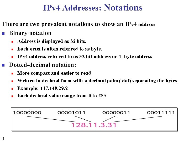
IPv 4 Addresses: Notations There are two prevalent notations to show an IPv 4 address n Binary notation n n Dotted-decimal notation: n n 4 Address is displayed as 32 bits. Each octet is often referred to as byte. IPv 4 address referred to as 32 -bit address or 4 - byte address More compact and easier to read Written in decimal form with a decimal point( dot) separating the bytes Example: 117. 149. 2 Each decimal value range from 0 to 255
Address Allocation n n How are the block allocated? The address allocation is given to global authority called n n n 5 Internet Assigned Number Authority (IANA) IANA does not allocate addresses to individual organizations It assigns a large block of addresses to an ISP
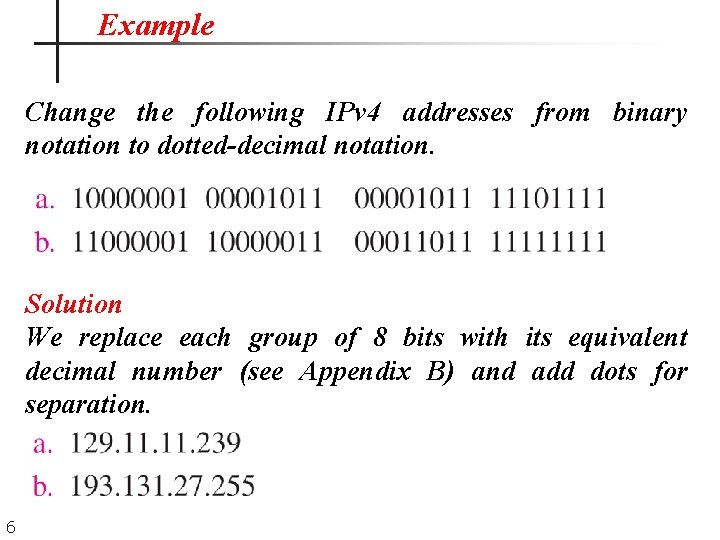
Example Change the following IPv 4 addresses from binary notation to dotted-decimal notation. Solution We replace each group of 8 bits with its equivalent decimal number (see Appendix B) and add dots for separation. 6
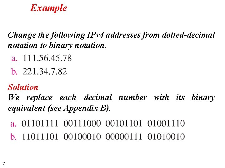
Example Change the following IPv 4 addresses from dotted-decimal notation to binary notation. Solution We replace each decimal number with its binary equivalent (see Appendix B). 7
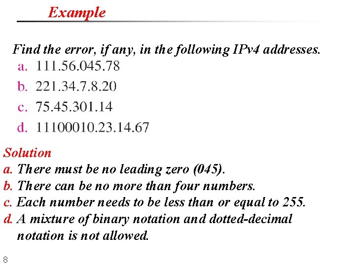
Example Find the error, if any, in the following IPv 4 addresses. Solution a. There must be no leading zero (045). b. There can be no more than four numbers. c. Each number needs to be less than or equal to 255. d. A mixture of binary notation and dotted-decimal notation is not allowed. 8
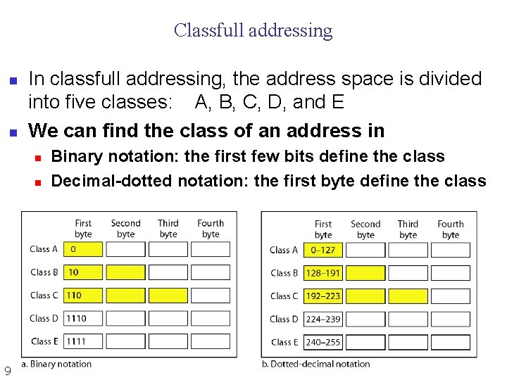
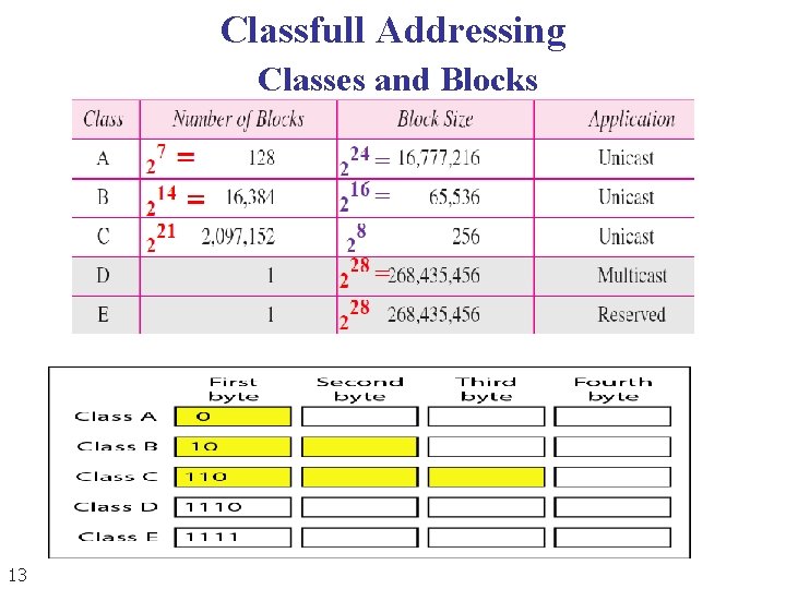
Classfull addressing n n In classfull addressing, the address space is divided into five classes: A, B, C, D, and E We can find the class of an address in n n 9 Binary notation: the first few bits define the class Decimal-dotted notation: the first byte define the class
Classfull addressing n n In classfull addressing, the address space is divided into 5 classes: A, B, C, D, and E. Addresses in Classes A, B and C are uniast ddresses A host needs to have at least one unicast address to be able to send packet (Source). Addresses in Class D are for multicast address n n 10 Used only for destination Addresses in class E are reserved
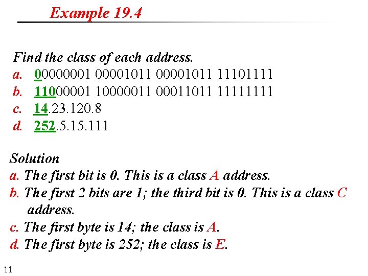
Example 19. 4 Find the class of each address. a. 00000001011 11101111 b. 110000011 00011011 1111 c. 14. 23. 120. 8 d. 252. 5. 111 Solution a. The first bit is 0. This is a class A address. b. The first 2 bits are 1; the third bit is 0. This is a class C address. c. The first byte is 14; the class is A. d. The first byte is 252; the class is E. 11
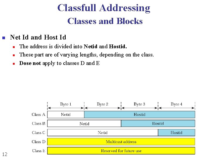
Classfull Addressing Classes and Blocks n Net Id and Host Id n n n 12 The address is divided into Netid and Hostid. These part are of varying lengths, depending on the class. Dose not apply to classes D and E
Classfull Addressing Classes and Blocks 13
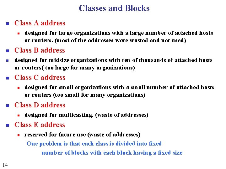
Classes and Blocks n Class A address n n Class B address designed for midsize organizations with ten of thousands of attached hosts or routers( too large for many organizations) Class C address n n designed for multicasting. (waste of addresses) Class E address n 14 designed for small organizations with a small number of attached hosts or routers (too small for many organizations) Class D address n n designed for large organizations with a large number of attached hosts or routers. (most of the addresses were wasted and not used) reserved for future use (waste of addresses) One problem is that each class is divided into fixed number of blocks with each block having a fixed size
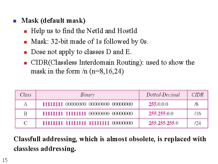
n Mask (default mask) n Help us to find the Net. Id and Host. Id n Mask: 32 -bit made of 1 s followed by 0 s. n Dose not apply to classes D and E. n CIDR(Classless Interdomain Routing): used to show the mask in the form /n (n=8, 16, 24) Classfull addressing, which is almost obsolete, is replaced with classless addressing. 15
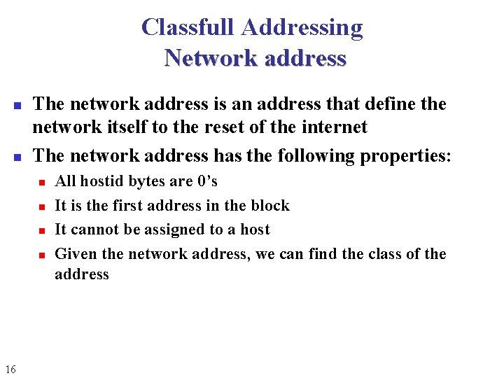
Classfull Addressing Network address n n The network address is an address that define the network itself to the reset of the internet The network address has the following properties: n n 16 All hostid bytes are 0’s It is the first address in the block It cannot be assigned to a host Given the network address, we can find the class of the address
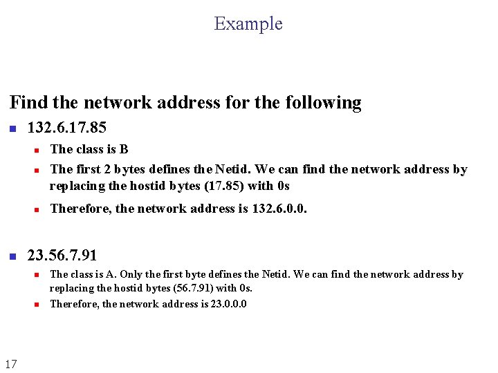
Example Find the network address for the following n 132. 6. 17. 85 n The class is B The first 2 bytes defines the Netid. We can find the network address by replacing the hostid bytes (17. 85) with 0 s n Therefore, the network address is 132. 6. 0. 0. n n 23. 56. 7. 91 n n 17 The class is A. Only the first byte defines the Netid. We can find the network address by replacing the hostid bytes (56. 7. 91) with 0 s. Therefore, the network address is 23. 0. 0. 0
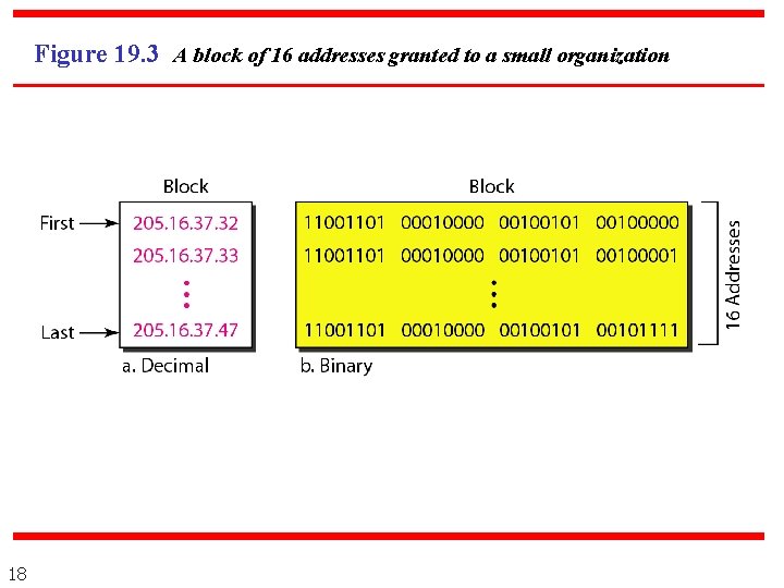
Figure 19. 3 A block of 16 addresses granted to a small organization 18
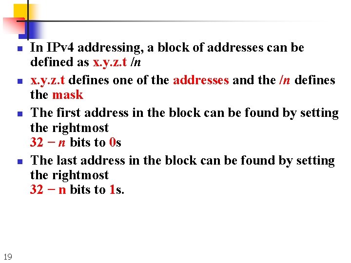
n n 19 In IPv 4 addressing, a block of addresses can be defined as x. y. z. t /n x. y. z. t defines one of the addresses and the /n defines the mask The first address in the block can be found by setting the rightmost 32 − n bits to 0 s The last address in the block can be found by setting the rightmost 32 − n bits to 1 s.
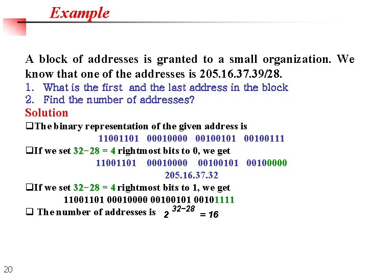
Example A block of addresses is granted to a small organization. We know that one of the addresses is 205. 16. 37. 39/28. 1. What is the first and the last address in the block 2. Find the number of addresses? Solution q. The binary representation of the given address is 11001101 00010000 00100101 00100111 q. If we set 32− 28 = 4 rightmost bits to 0, we get 11001101 00010000 00100101 00100000 205. 16. 37. 32 q. If we set 32− 28 = 4 rightmost bits to 1, we get 11001101 00010000 00100101111 q The number of addresses is 2 32− 28 = 16 20
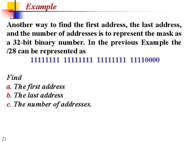
Example Another way to find the first address, the last address, and the number of addresses is to represent the mask as a 32 -bit binary number. In the previous Example the /28 can be represented as 11111111 11110000 Find a. The first address b. The last address c. The number of addresses. 21
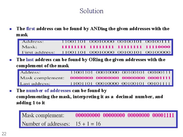
Solution n 22 The first address can be found by ANDing the given addresses with the mask The last address can be found by ORing the given addresses with the complement of the mask The number of addresses can be found by complementing the mask, interpreting it as a decimal number, and adding 1 to it
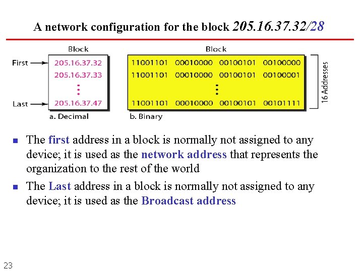
A network configuration for the block 205. 16. 37. 32/28 n n 23 The first address in a block is normally not assigned to any device; it is used as the network address that represents the organization to the rest of the world The Last address in a block is normally not assigned to any device; it is used as the Broadcast address
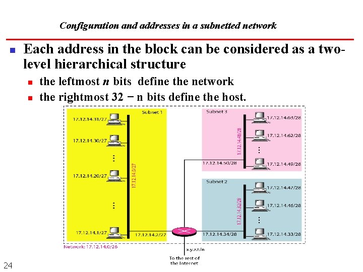
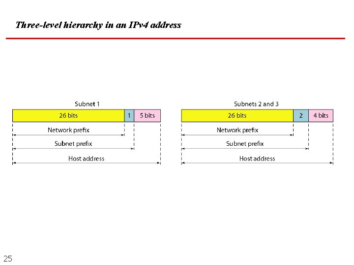
Configuration and addresses in a subnetted network n Each address in the block can be considered as a twolevel hierarchical structure n n 24 the leftmost n bits define the network the rightmost 32 − n bits define the host.
Three-level hierarchy in an IPv 4 address 25
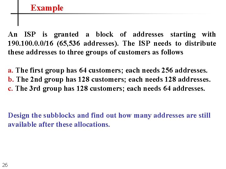
Example An ISP is granted a block of addresses starting with 190. 100. 0. 0/16 (65, 536 addresses). The ISP needs to distribute these addresses to three groups of customers as follows a. The first group has 64 customers; each needs 256 addresses. b. The 2 nd group has 128 customers; each needs 128 addresses. c. The 3 rd group has 128 customers; each needs 64 addresses. Design the subblocks and find out how many addresses are still available after these allocations. 26
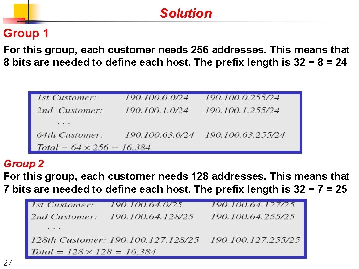
Solution Group 1 For this group, each customer needs 256 addresses. This means that 8 bits are needed to define each host. The prefix length is 32 − 8 = 24 Group 2 For this group, each customer needs 128 addresses. This means that 7 bits are needed to define each host. The prefix length is 32 − 7 = 25 27
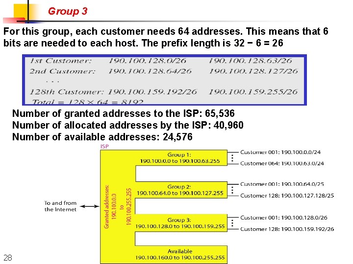
Group 3 For this group, each customer needs 64 addresses. This means that 6 bits are needed to each host. The prefix length is 32 − 6 = 26 Number of granted addresses to the ISP: 65, 536 Number of allocated addresses by the ISP: 40, 960 Number of available addresses: 24, 576 28
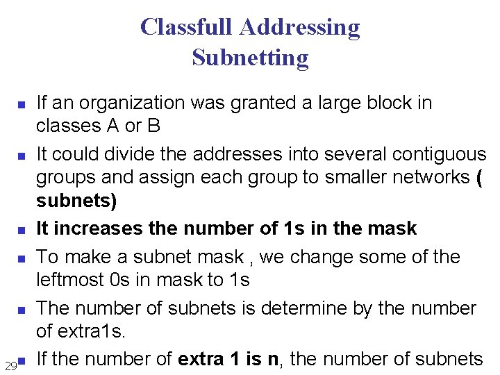
Classfull Addressing Subnetting n n n 29 n If an organization was granted a large block in classes A or B It could divide the addresses into several contiguous groups and assign each group to smaller networks ( subnets) It increases the number of 1 s in the mask To make a subnet mask , we change some of the leftmost 0 s in mask to 1 s The number of subnets is determine by the number of extra 1 s. If the number of extra 1 is n, the number of subnets
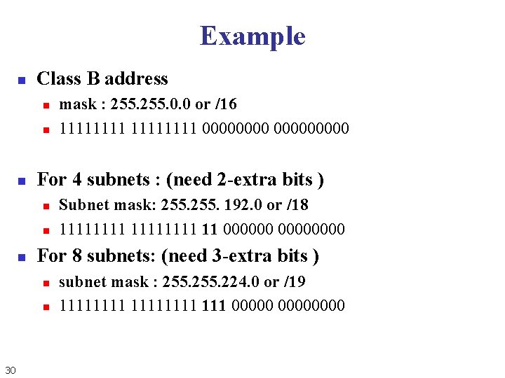
Example n Class B address n n n For 4 subnets : (need 2 -extra bits ) n n n Subnet mask: 255. 192. 0 or /18 11111111 11 00000000 For 8 subnets: (need 3 -extra bits ) n n 30 mask : 255. 0. 0 or /16 11111111 000000000 subnet mask : 255. 224. 0 or /19 11111111 111 00000000
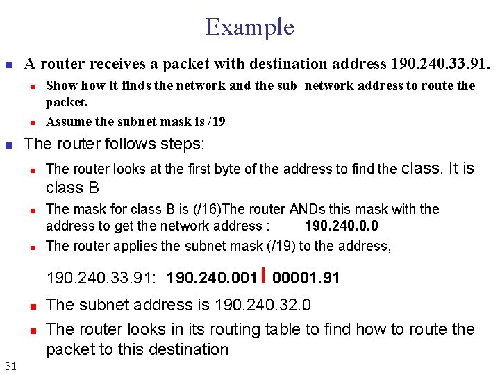
Example n A router receives a packet with destination address 190. 240. 33. 91. n n n Show it finds the network and the sub_network address to route the packet. Assume the subnet mask is /19 The router follows steps: n The router looks at the first byte of the address to find the class. It is class B n n The mask for class B is (/16)The router ANDs this mask with the address to get the network address : 190. 240. 0. 0 The router applies the subnet mask (/19) to the address, ı 190. 240. 33. 91: 190. 240. 001 00001. 91 n n 31 The subnet address is 190. 240. 32. 0 The router looks in its routing table to find how to route the packet to this destination
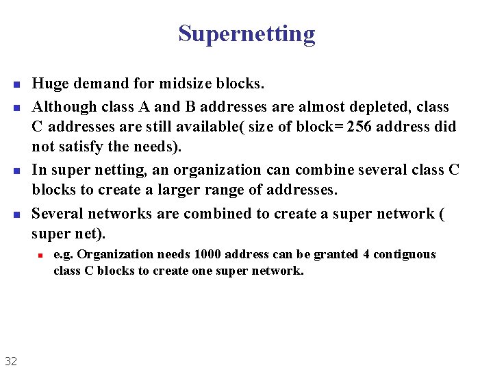
Supernetting n n Huge demand for midsize blocks. Although class A and B addresses are almost depleted, class C addresses are still available( size of block= 256 address did not satisfy the needs). In super netting, an organization can combine several class C blocks to create a larger range of addresses. Several networks are combined to create a super network ( super net). n 32 e. g. Organization needs 1000 address can be granted 4 contiguous class C blocks to create one super network.
Subnetting n Collision domain n n Broadcast domain n 33 Are the connected physical network segments where collisions can occur A group of collision domains that are connected by layer 2 devices
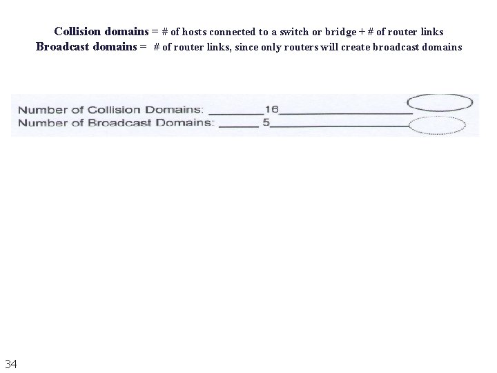
Collision domains = # of hosts connected to a switch or bridge + # of router links Broadcast domains = # of router links, since only routers will create broadcast domains 34
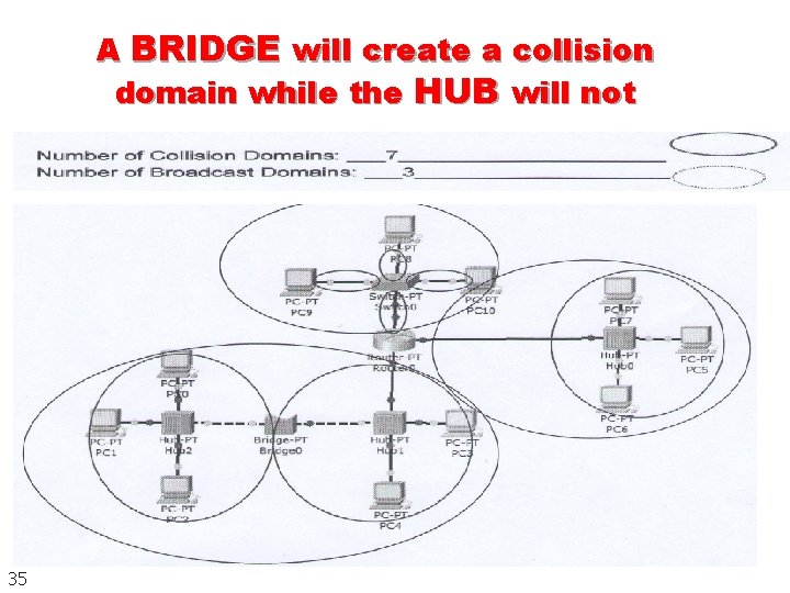
A BRIDGE will create a collision domain while the HUB will not 35
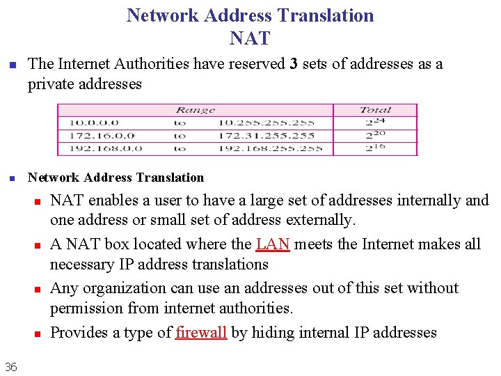
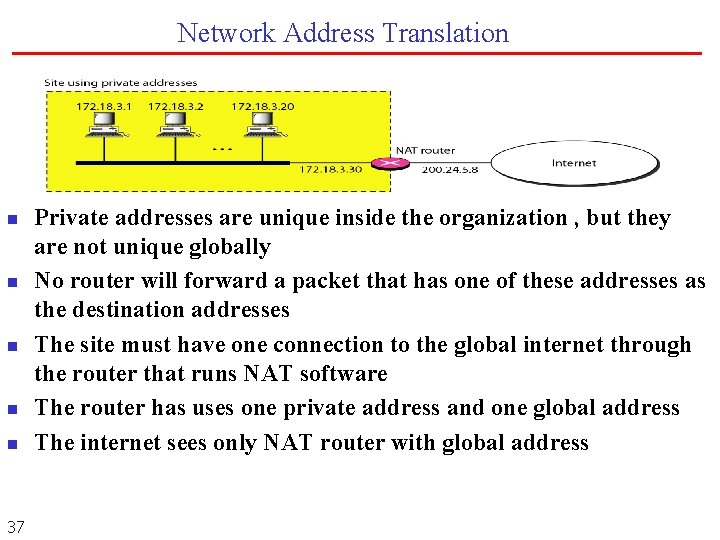
Network Address Translation NAT n n The Internet Authorities have reserved 3 sets of addresses as a private addresses Network Address Translation n n 36 NAT enables a user to have a large set of addresses internally and one address or small set of address externally. A NAT box located where the LAN meets the Internet makes all necessary IP address translations Any organization can use an addresses out of this set without permission from internet authorities. Provides a type of firewall by hiding internal IP addresses
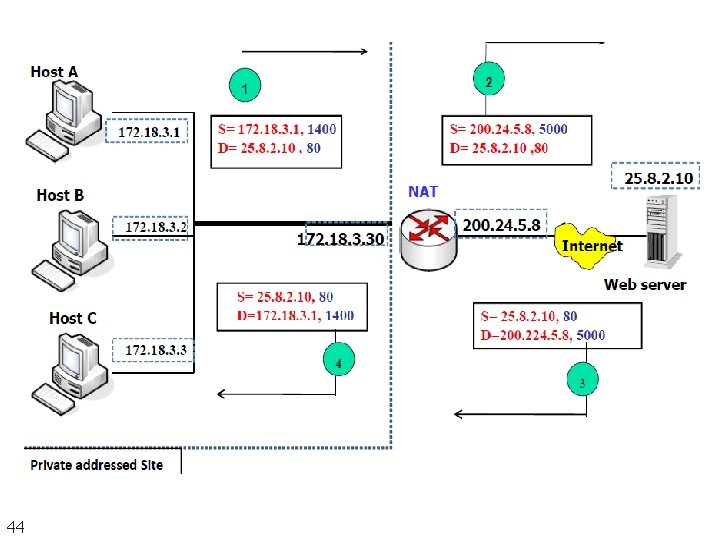
Network Address Translation n n 37 Private addresses are unique inside the organization , but they are not unique globally No router will forward a packet that has one of these addresses as the destination addresses The site must have one connection to the global internet through the router that runs NAT software The router has uses one private address and one global address The internet sees only NAT router with global address
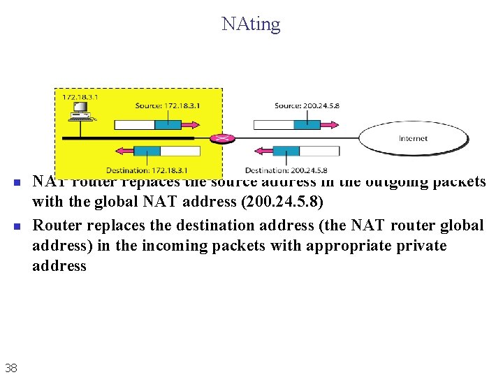
NAting n n 38 NAT router replaces the source address in the outgoing packets with the global NAT address (200. 24. 5. 8) Router replaces the destination address (the NAT router global address) in the incoming packets with appropriate private address
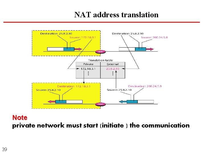
NAT address translation Note private network must start (initiate ) the communication 39
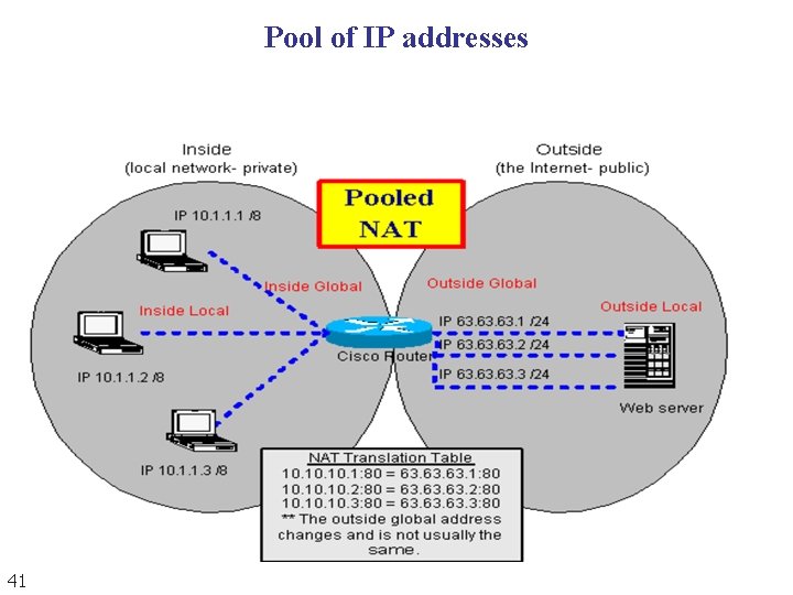
NAT address translation Using pool of IP addresses n Restriction n For example n n 40 Since the NAT router has only one global address, only one private network host can To remove the previous restriction, the NAT router uses a pool of global addresses access the same external host instead of using one global address 200. 24. 5. 8 , the NAT router can uses 4 addresses (200. 24. 5. 8, 200. 24. 5. 9, 200. 24. 5. 10, 200. 24. 5. 11). In this case 4 private network hosts can communicate the same external host at the same time because each pair of addresses defines a connection
Pool of IP addresses 41
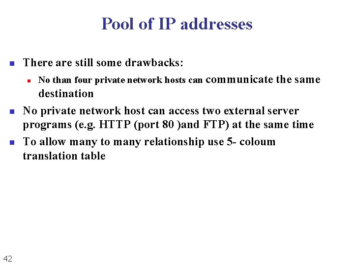
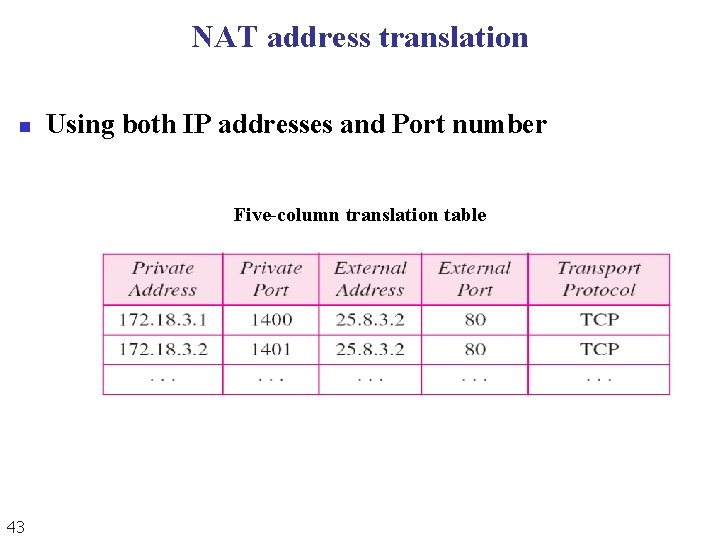
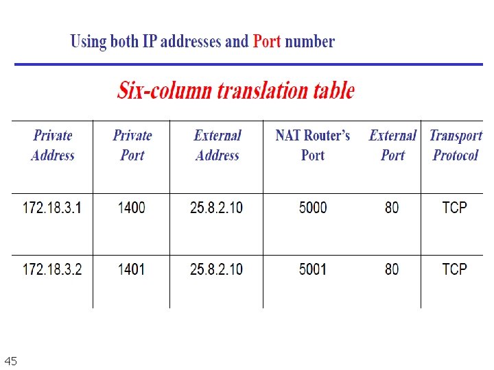
Pool of IP addresses n There are still some drawbacks: n n n 42 No than four private network hosts can communicate the same destination No private network host can access two external server programs (e. g. HTTP (port 80 )and FTP) at the same time To allow many to many relationship use 5 - coloum translation table
NAT address translation n Using both IP addresses and Port number Five-column translation table 43
44
45
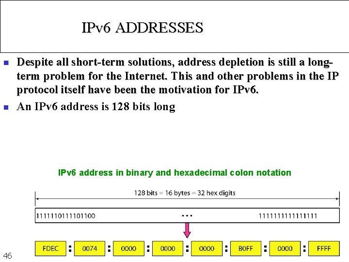
IPv 6 ADDRESSES n n Despite all short-term solutions, address depletion is still a longterm problem for the Internet. This and other problems in the IP protocol itself have been the motivation for IPv 6. An IPv 6 address is 128 bits long IPv 6 address in binary and hexadecimal colon notation 46
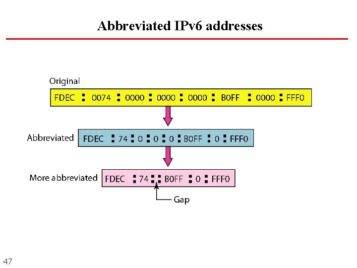
Abbreviated IPv 6 addresses 47
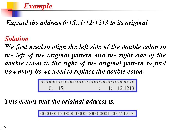
Example Expand the address 0: 15: : 1: 1213 to its original. Solution We first need to align the left side of the double colon to the left of the original pattern and the right side of the double colon to the right of the original pattern to find how many 0 s we need to replace the double colon. This means that the original address is. 48
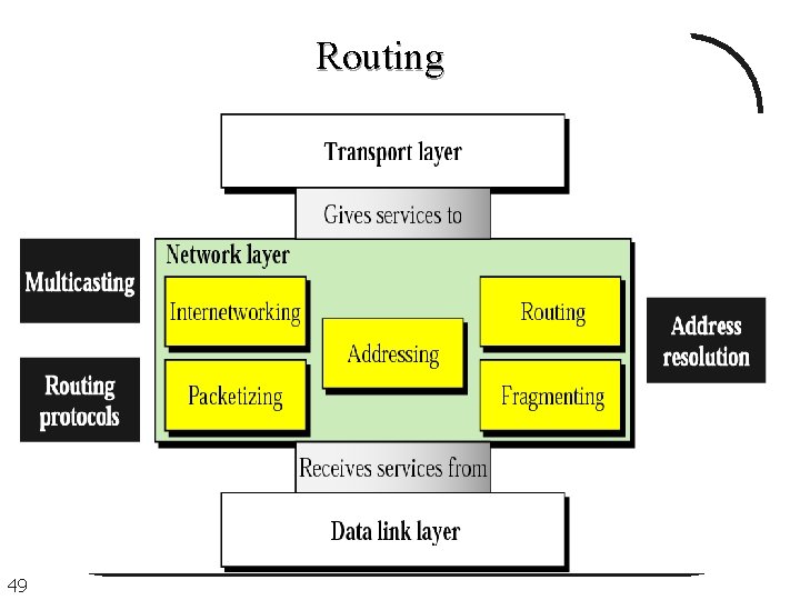
Routing 49
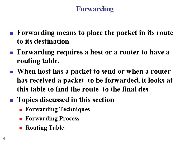
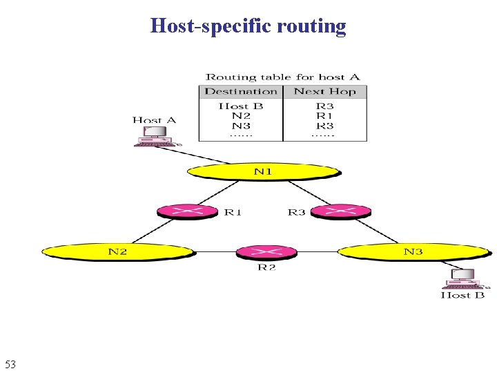
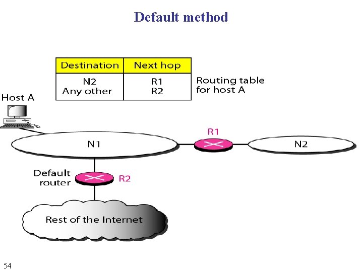
Forwarding n n Forwarding means to place the packet in its route to its destination. Forwarding requires a host or a router to have a routing table. When host has a packet to send or when a router has received a packet to be forwarded, it looks at this table to find the route to the final des Topics discussed in this section n 50 Forwarding Techniques Forwarding Process Routing Table
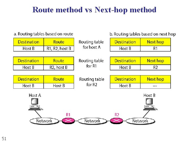
Route method vs Next-hop method 51
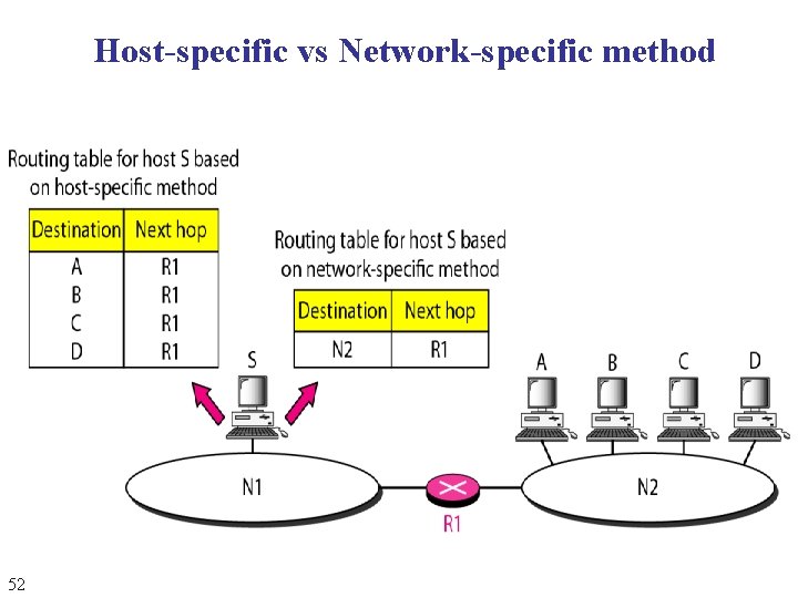
Host-specific vs Network-specific method 52
Host-specific routing 53
Default method 54
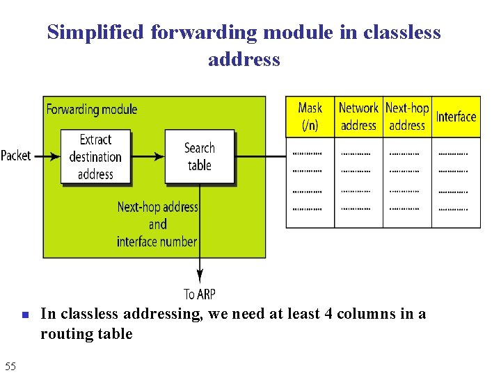
Simplified forwarding module in classless address n 55 In classless addressing, we need at least 4 columns in a routing table
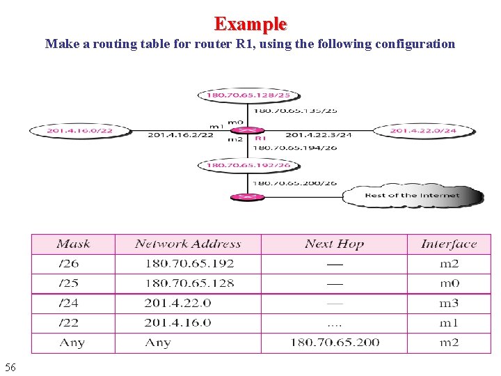
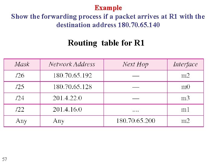
Example Make a routing table for router R 1, using the following configuration 56
Example Show the forwarding process if a packet arrives at R 1 with the destination address 180. 70. 65. 140 Routing table for R 1 57
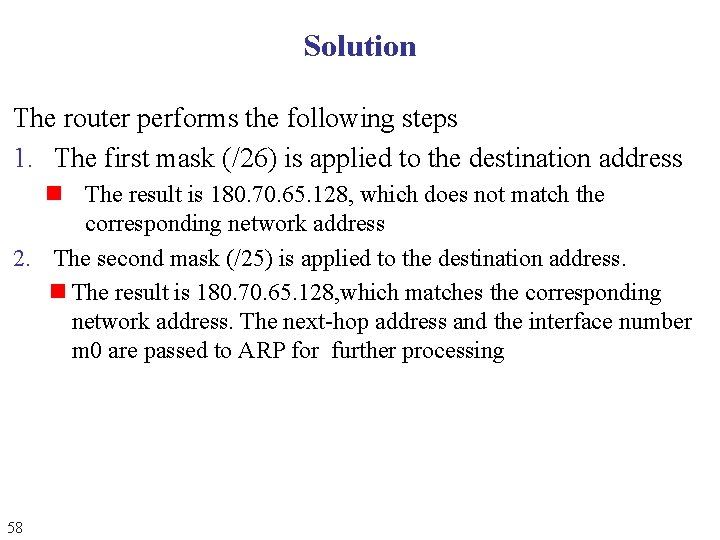
Solution The router performs the following steps 1. The first mask (/26) is applied to the destination address n The result is 180. 70. 65. 128, which does not match the corresponding network address 2. The second mask (/25) is applied to the destination address. n The result is 180. 70. 65. 128, which matches the corresponding network address. The next-hop address and the interface number m 0 are passed to ARP for further processing 58
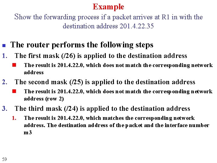
Example Show the forwarding process if a packet arrives at R 1 in with the destination address 201. 4. 22. 35 n The router performs the following steps 1. The first mask (/26) is applied to the destination address n The result is 201. 4. 22. 0, which does not match the corresponding network address 2. The second mask (/25) is applied to the destination address n The result is 201. 4. 22. 0, which does not match the corresponding network address (row 2) 3. The third mask (/24) is applied to the destination address 1. 59 The result is 201. 4. 22. 0, which matches the corresponding network address. The destination address of the packet and the interface number m 3
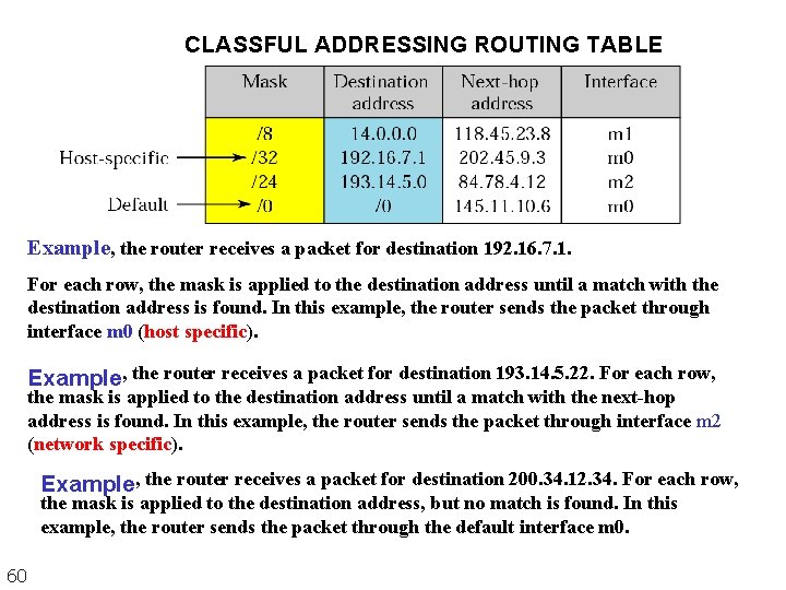
CLASSFUL ADDRESSING ROUTING TABLE Example, the router receives a packet for destination 192. 16. 7. 1. For each row, the mask is applied to the destination address until a match with the destination address is found. In this example, the router sends the packet through interface m 0 (host specific). Example, the router receives a packet for destination 193. 14. 5. 22. For each row, the mask is applied to the destination address until a match with the next-hop address is found. In this example, the router sends the packet through interface m 2 (network specific). Example, the router receives a packet for destination 200. 34. 12. 34. For each row, the mask is applied to the destination address, but no match is found. In this example, the router sends the packet through the default interface m 0. 60
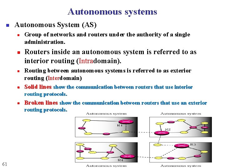
Autonomous systems n Autonomous System (AS) n n Group of networks and routers under the authority of a single administration. Routers inside an autonomous system is referred to as interior routing (Intradomain). Routing between autonomous systems is referred to as exterior routing (Interdomain) Solid lines show the communication between routers that use interior routing protocols. n Broken lines show the communication between routers that use an exterior routing protocols. 61
Example Show the forwarding process if a packet arrives at R 1 with the destination address 18. 24. 32. 78 n 62 This time all masks are applied, one by one, to the destination address, but no matching network address is found. When it reaches the end of the table, the module gives the next-hop address 180. 70. 65. 200 and interface number m 2 to ARP. This is probably an out going package that needs to be sent, via the default router, to some place else in the Internet.
Routing n n n Packet go from source to destination via routers. Router consults the routing table. Routing table can be n n Routing protocols are needed to create the routing tables dynamically. A routing protocol is a combination of rules and procedures that n n 63 Static: does not change automatically (manual entries) Dynamic: updated automatically when there is change in the Internet Lets routers in the internet inform one another of changes. Allows routers to share whatever they know about the internet or their neighborhood.
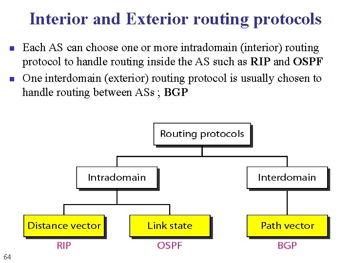
Interior and Exterior routing protocols n n 64 Each AS can choose one or more intradomain (interior) routing protocol to handle routing inside the AS such as RIP and OSPF One interdomain (exterior) routing protocol is usually chosen to handle routing between ASs ; BGP
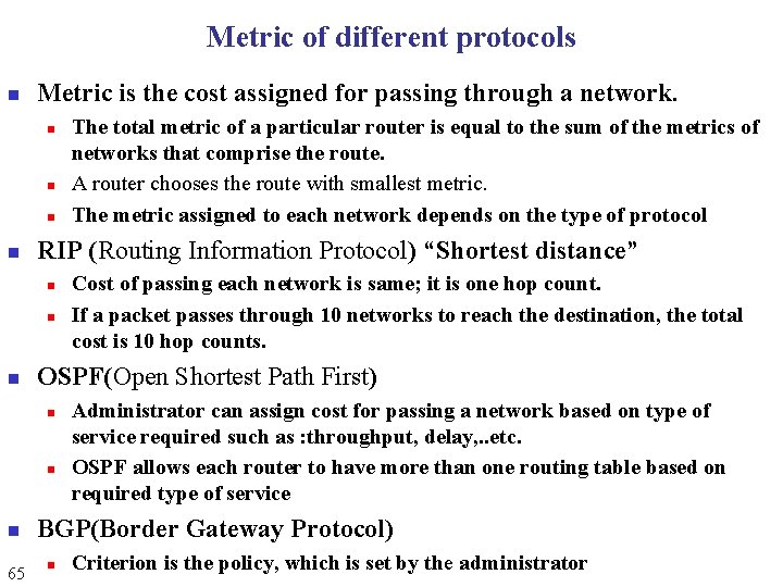
Metric of different protocols n Metric is the cost assigned for passing through a network. n n RIP (Routing Information Protocol) “Shortest distance” n n 65 Cost of passing each network is same; it is one hop count. If a packet passes through 10 networks to reach the destination, the total cost is 10 hop counts. OSPF(Open Shortest Path First) n n The total metric of a particular router is equal to the sum of the metrics of networks that comprise the route. A router chooses the route with smallest metric. The metric assigned to each network depends on the type of protocol Administrator can assign cost for passing a network based on type of service required such as : throughput, delay, . . etc. OSPF allows each router to have more than one routing table based on required type of service BGP(Border Gateway Protocol) n Criterion is the policy, which is set by the administrator
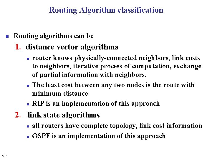
Routing Algorithm classification n Routing algorithms can be 1. distance vector algorithms n n n router knows physically-connected neighbors, link costs to neighbors, iterative process of computation, exchange of partial information with neighbors. The least cost between any two nodes is the route with minimum distance RIP is an implementation of this approach 2. link state algorithms n n 66 all routers have complete topology, link cost information OSPF is an implementation of this approach
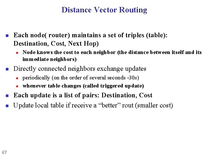
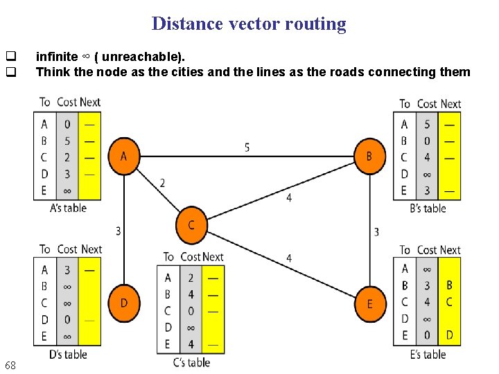
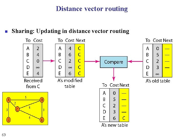
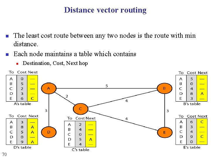
Distance Vector Routing n Each node( router) maintains a set of triples (table): Destination, Cost, Next Hop) n n Directly connected neighbors exchange updates n n 67 Node knows the cost to each neighbor (the distance between itself and its immediate neighbors) periodically (on the order of several seconds -30 s) whenever table changes (called triggered update) Each update is a list of pairs: Destination, Cost Update local table if receive a “better” rout (smaller cost)
Distance vector routing q q 68 infinite ∞ ( unreachable). Think the node as the cities and the lines as the roads connecting them
Distance vector routing n 69 Sharing: Updating in distance vector routing
Distance vector routing n n The least cost route between any two nodes is the route with min distance. Each node maintains a table which contains n 70 Destination, Cost, Next hop
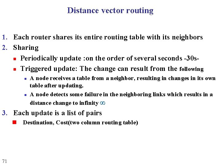
Distance vector routing 1. Each router shares its entire routing table with its neighbors 2. Sharing n Periodically update : on the order of several seconds -30 sn Triggered update: The change can result from the following n n A node receives a table from a neighbor, resulting in changes in its own table after updating. A node detects some failure in the neighboring links which results in a distance change to infinity ∞ 3. Each update is a list of pairs n 71 Destination, Cost(two column routing table)
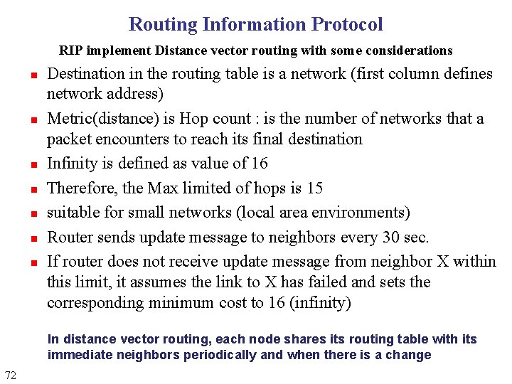
Routing Information Protocol RIP implement Distance vector routing with some considerations n n n n Destination in the routing table is a network (first column defines network address) Metric(distance) is Hop count : is the number of networks that a packet encounters to reach its final destination Infinity is defined as value of 16 Therefore, the Max limited of hops is 15 suitable for small networks (local area environments) Router sends update message to neighbors every 30 sec. If router does not receive update message from neighbor X within this limit, it assumes the link to X has failed and sets the corresponding minimum cost to 16 (infinity) In distance vector routing, each node shares its routing table with its immediate neighbors periodically and when there is a change 72
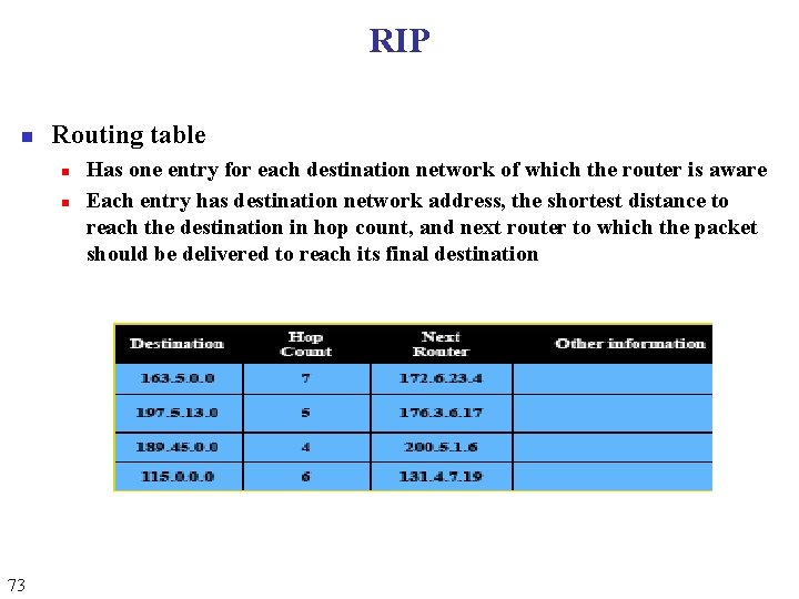
RIP n Routing table n n 73 Has one entry for each destination network of which the router is aware Each entry has destination network address, the shortest distance to reach the destination in hop count, and next router to which the packet should be delivered to reach its final destination
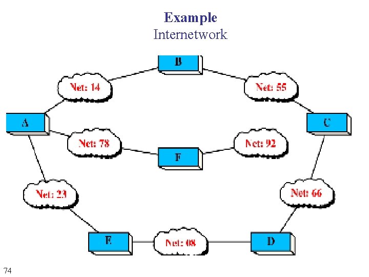
Example Internetwork 74
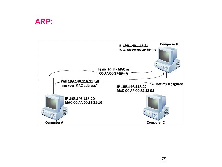
ARP: 75
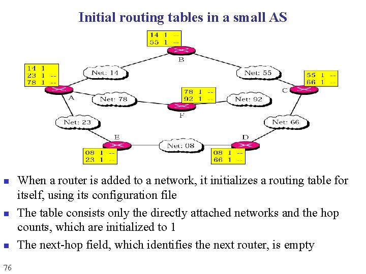
Initial routing tables in a small AS n n n 76 When a router is added to a network, it initializes a routing table for itself, using its configuration file The table consists only the directly attached networks and the hop counts, which are initialized to 1 The next-hop field, which identifies the next router, is empty
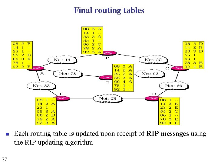
Final routing tables n 77 Each routing table is updated upon receipt of RIP messages using the RIP updating algorithm
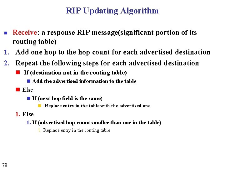
RIP Updating Algorithm Receive: a response RIP message(significant portion of its routing table) 1. Add one hop to the hop count for each advertised destination 2. Repeat the following steps for each advertised destination n n If (destination not in the routing table) n Add the advertised information to the table n Else n If (next-hop field is the same) n Replace entry in the table with the advertised one. 1. Else 1. If (advertised hop count smaller than one in the table) 1. Replace entry in the routing table 78
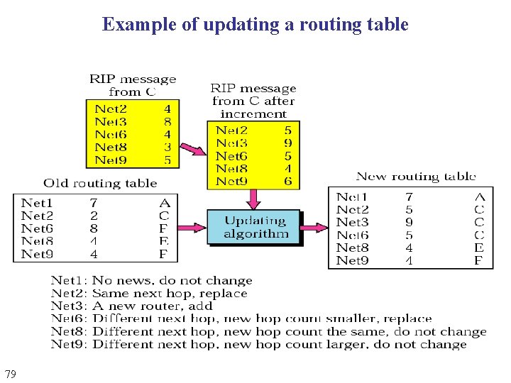
Example of updating a routing table 79
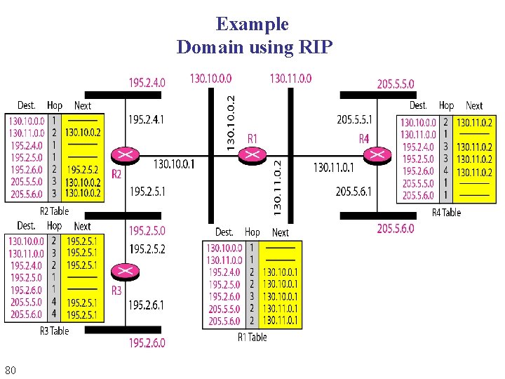
Example Domain using RIP 80
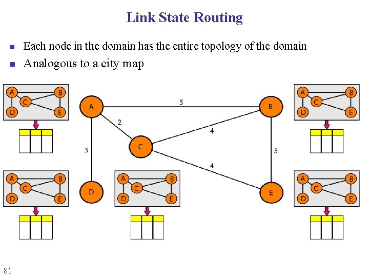
Link State Routing n Each node in the domain has the entire topology of the domain n Analogous to a city map 81
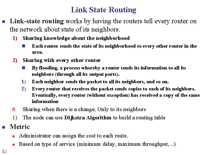
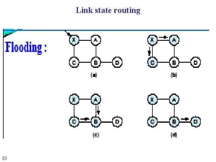
Link State Routing n Link-state routing works by having the routers tell every router on the network about state of its neighbors. 1) Sharing knowledge about the neighborhood n Each router sends the state of its neighborhood to every other router in the area. 2) Sharing with every other router n 1) 2) By flooding, a process whereby a router sends its information to all its neighbors (through all its output ports). Each neighbor sends the packet to all its neighbors, and so on. Every router that receives the packet sends copies to each of its neighbors. Eventually, every router (without exception) has received a copy of the same information n Sharing when there is a change; Only to its neighbors 1) The node can use Dijkstra Algorithm to build a routing table n Metric n n 82 Administrator can assign the cost to each route. Based on type of service (minimum delay, maximum throughput, . . )
Link state routing 83
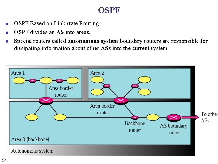
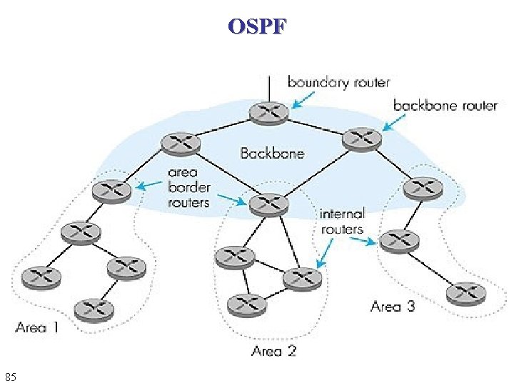
OSPF n n n 84 OSPF Based on Link state Routing OSPF divides an AS into areas. Special routers called autonomous system boundary routers are responsible for dissipating information about other ASs into the current system
OSPF 85
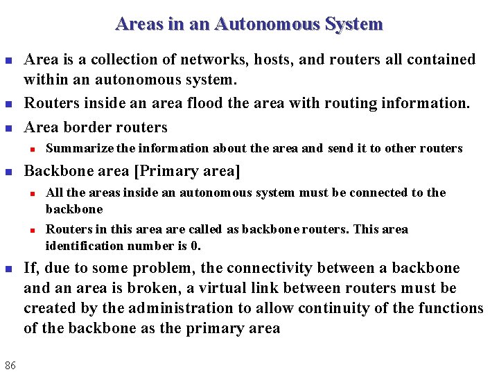
Areas in an Autonomous System n n n Area is a collection of networks, hosts, and routers all contained within an autonomous system. Routers inside an area flood the area with routing information. Area border routers n n Backbone area [Primary area] n n n 86 Summarize the information about the area and send it to other routers All the areas inside an autonomous system must be connected to the backbone Routers in this area are called as backbone routers. This area identification number is 0. If, due to some problem, the connectivity between a backbone and an area is broken, a virtual link between routers must be created by the administration to allow continuity of the functions of the backbone as the primary area
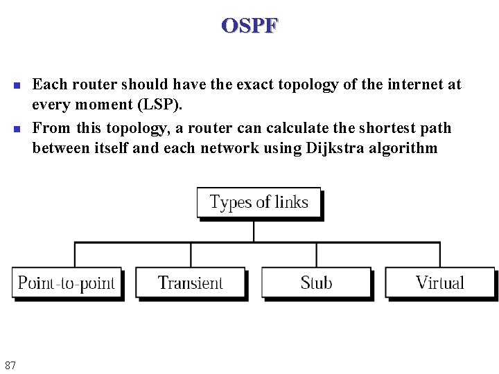
OSPF n n 87 Each router should have the exact topology of the internet at every moment (LSP). From this topology, a router can calculate the shortest path between itself and each network using Dijkstra algorithm
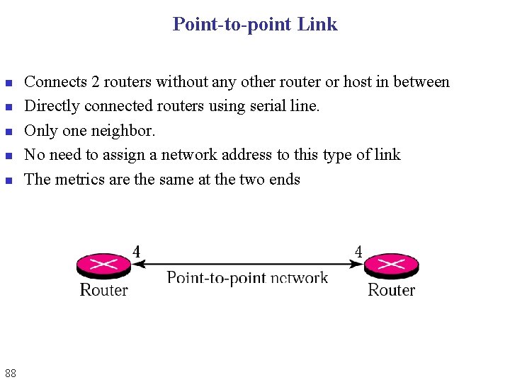
Point-to-point Link n n n 88 Connects 2 routers without any other router or host in between Directly connected routers using serial line. Only one neighbor. No need to assign a network address to this type of link The metrics are the same at the two ends
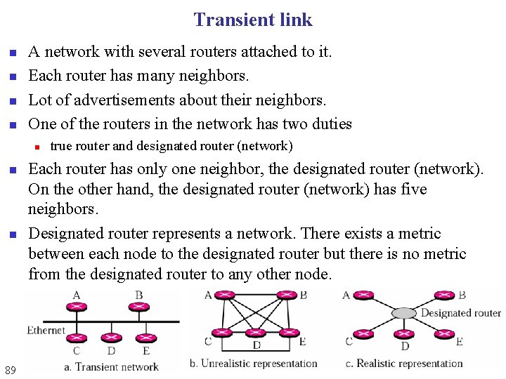
Transient link n n A network with several routers attached to it. Each router has many neighbors. Lot of advertisements about their neighbors. One of the routers in the network has two duties n n n 89 true router and designated router (network) Each router has only one neighbor, the designated router (network). On the other hand, the designated router (network) has five neighbors. Designated router represents a network. There exists a metric between each node to the designated router but there is no metric from the designated router to any other node.
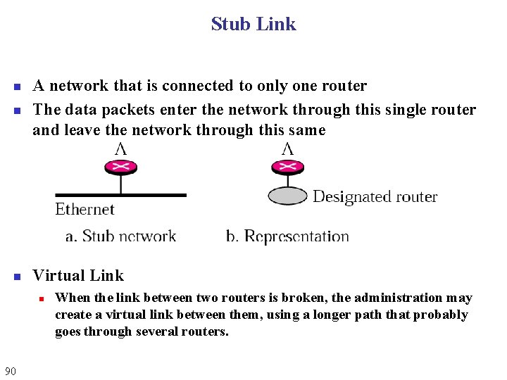
Stub Link n A network that is connected to only one router The data packets enter the network through this single router and leave the network through this same n Virtual Link n n 90 When the link between two routers is broken, the administration may create a virtual link between them, using a longer path that probably goes through several routers.
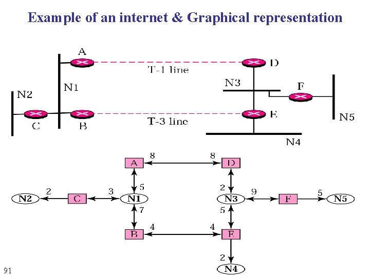
Example of an internet & Graphical representation 91
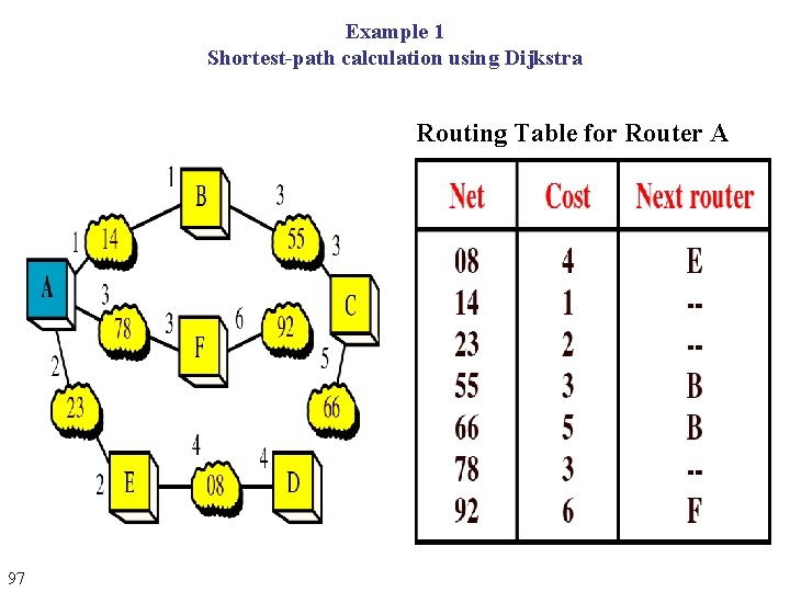
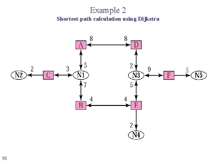
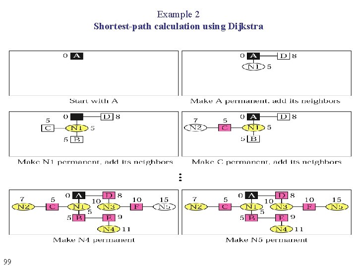
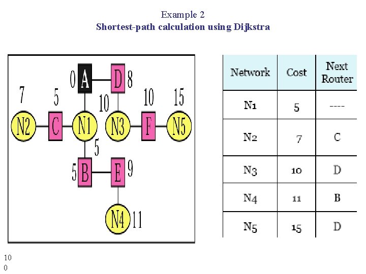
Dijkstra Algorithm n n Calculates the shortest path between two points on a network, using a graph made up of nodes and edges. Algorithm divides the nodes into two sets n n 92 tentative and permanent It chooses nodes, makes them tentative, examines them, and if they pass the criteria, makes them permanent
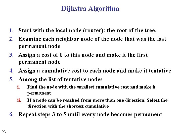
Dijkstra Algorithm 1. Start with the local node (router): the root of the tree. 2. Examine each neighbor node of the node that was the last permanent node 3. Assign a cost of 0 to this node and make it the first permanent node 4. Assign a cumulative cost to each node and make it tentative 5. Among the list of tentative nodes i. ii. Find the node with the smallest cumulative cost and make it permanent If a node can be reached from more than one direction. Select the direction with the shortest cumulative 6. Repeat steps 3 to 5 until every node becomes permanent 93
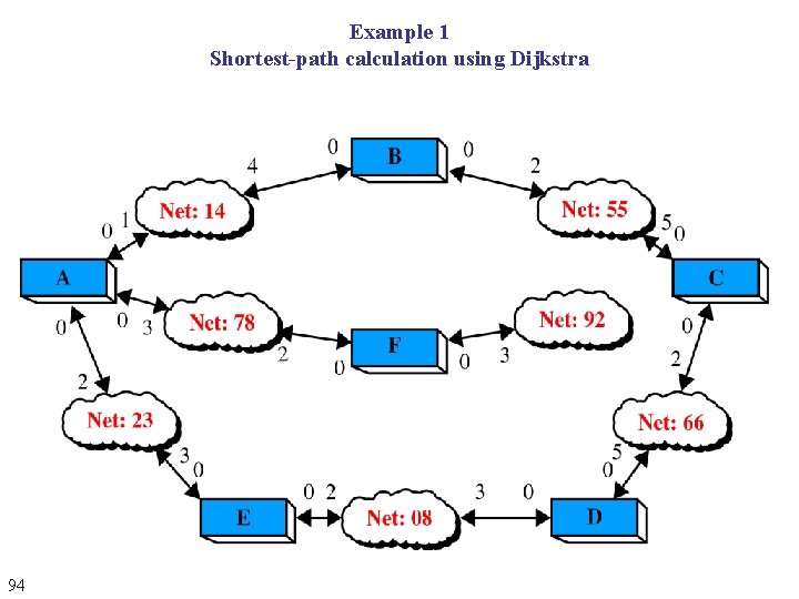
Example 1 Shortest-path calculation using Dijkstra 94
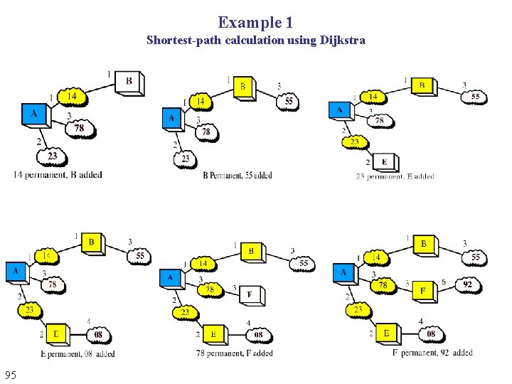
Example 1 Shortest-path calculation using Dijkstra 95
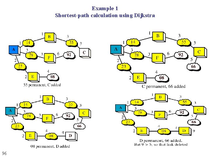
Example 1 Shortest-path calculation using Dijkstra 96
Example 1 Shortest-path calculation using Dijkstra Routing Table for Router A 97
Example 2 Shortest-path calculation using Dijkstra 98
Example 2 Shortest-path calculation using Dijkstra 99
Example 2 Shortest-path calculation using Dijkstra 10 0
OSPF Reaction to Failure n If a link fails, n n n Router sets link distance to infinity & floods the network with an update packet All routers immediately update their link database &recalculate their shortest paths Recovery quick NOTE n n n 10 1 OSPF differs from RIP in that each router knows the exact topology of the network OSPF reduces routing bandwidth usage OSPF is faster than RIP
DHCP n n 10 2 Dynamic Host Configuration Protocol Designed to provide information dynamically It is a client-server program Used to assign addresses to hosts dynamically
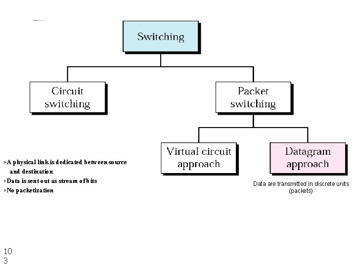
ØA physical link is dedicated between source and destination ØData is sent out as stream of bits ØNo packetization 10 3 Data are transmitted in discrete units (packets)
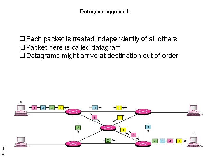
Datagram approach q. Each packet is treated independently of all others q. Packet here is called datagram q. Datagrams might arrive at destination out of order 10 4
Virtual Circuit n n Relationship between all packets belonging to a message is preserved A single route is chosen between sender and receiver at the beginning of the session Data are sent one after another WAN uses this approach which needs n n 10 5 Call setup to establish VC between sender and receiver Call teardown to delete the VC