Chapter 15 Site Plan Layout Introduction Site plans


 • Before beginning site plan layout, you need to find some")
 • Factors that influence site plans: – Sheet size – Plot")
 • Additional information determined before site plans: – Legal description –")


")

")


 • Grid survey – Divides site into a pattern")
")


- Slides: 20
Chapter 15 Site Plan Layout
Introduction • Site plans can be drawn on media ranging in size from 8 ½" × 11" up to 34" × 44" – Depends on purpose – Many local jurisdictions recommend site plans be drawn on an 8 ½" × 14" sheet
Introduction (cont’d. ) • Before beginning site plan layout, you need to find some important information – Often found in: • • Legal documents for the property Surveyor’s map Local assessor’s office Local zoning department
Introduction (cont’d. ) • Factors that influence site plans: – Sheet size – Plot size – Amount of information required – Amount of detail required
Introduction (cont’d. ) • Additional information determined before site plans: – Legal description – North direction – Existing roads, utilities, water, sewage disposal, drainage, and land slope – Zoning information – Size of proposed structures and elevations
Site Design Considerations • Factors to consider: – Driveway and lawn slope – Driveway width and turning radius – Room for installations and access to utilities – Easements – Grading rules – Remaining trees – Retaining walls
Rural Residential Fire Department Access and Site Planning • Standard guidelines: – Road clearances and load capacities – Grade – Dead ends and turnouts – Bridges and culverts – Fire safety zone and firefighter water supply – Property identification – Road coverings in wildfire zones
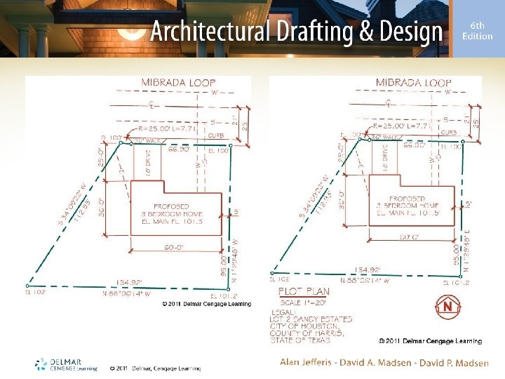
Laying Out Property Lines • Many plats have property lines that curve – Radius curve – Length of curve – Delta angle • Included angle
Laying Out Property Lines (cont’d. )
Steps in Site Planning • Steps to draw a site plan: – Select paper size – Lay out plot plan property lines – Lay out proposed structure – Complete property lines – Add dimensions, contour lines, and elevations – Complete the plot plan
Steps in Site Planning (cont’d. )
Site Plan Drawing Checklist • Check off items on the list provided in the text as you work on a basic site plan – Site plans for special applications may require additional information • • • Grading plan Subdivision plan Site analysis plan Planned unit development Commercial plan
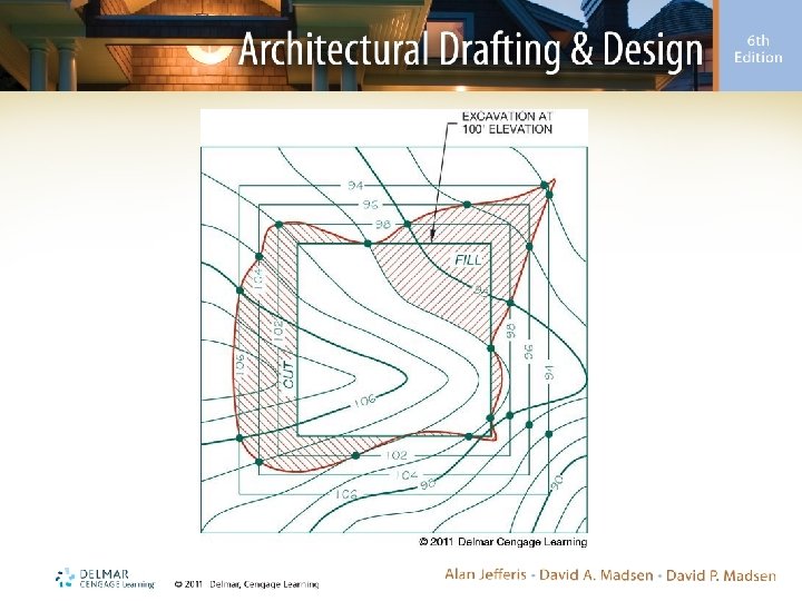
Drawing Contour Lines • Contour lines represent intervals of equal elevation – Elevations at points on the ground are recorded in field notes • Common methods: – Grid survey – Control point survey – Radial survey
Drawing Contour Lines (cont’d. ) • Grid survey – Divides site into a pattern similar to a checkerboard
Drawing Contour Lines (cont’d. )
Drawing Profiles
Drawing Grading Plans