
Chapter 15 IA64 Architecture Reflection on Superscalar Machines


- Slides: 45
Chapter 15 IA-64 Architecture
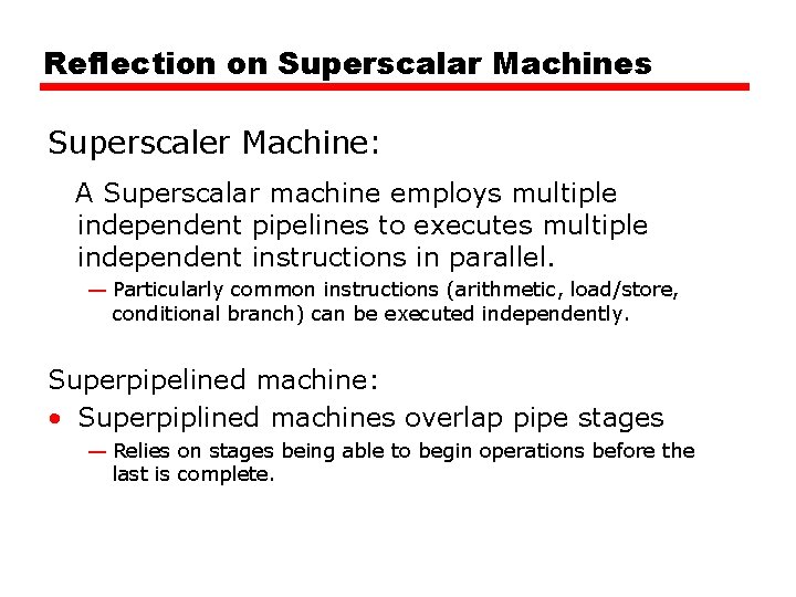
Reflection on Superscalar Machines Superscaler Machine: A Superscalar machine employs multiple independent pipelines to executes multiple independent instructions in parallel. — Particularly common instructions (arithmetic, load/store, conditional branch) can be executed independently. Superpipelined machine: • Superpiplined machines overlap pipe stages — Relies on stages being able to begin operations before the last is complete.
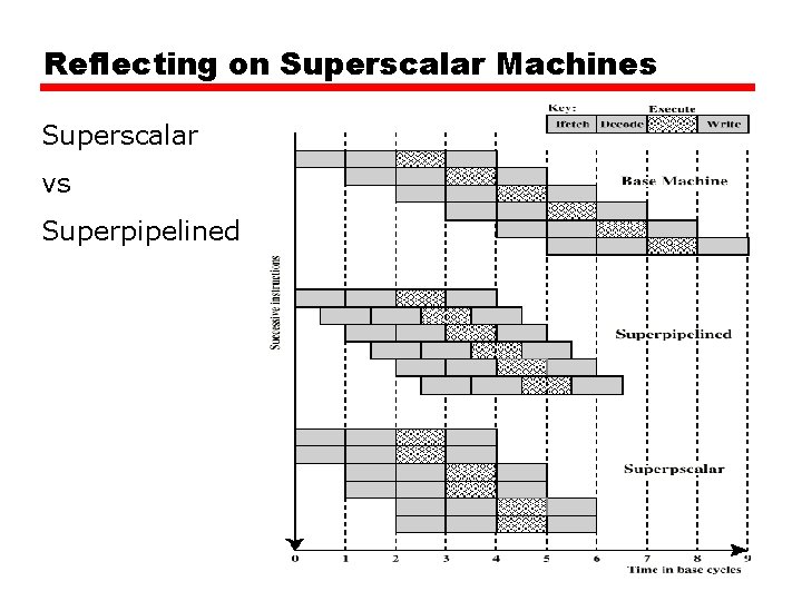
Reflecting on Superscalar Machines Example:
Reflecting on Superscalar Machines Superscalar vs Superpipelined
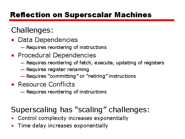
Reflection on Superscalar Machines Challenges: • Data Dependencies — Requires reordering of instructions • Procedural Dependencies — Requires reordering of fetch, execute, updating of registers — Requires register renaming — Requires “committing” or “retiring” instructions • Resource Conflicts — Requires reordering of instructions Superscaling has “scaling” challenges: • Control complexity increases exponentially • Time delay increases exponentially
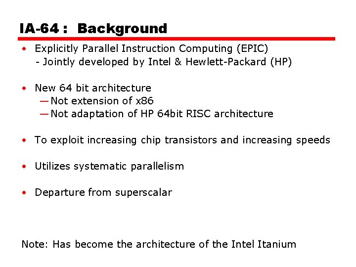
IA-64 : Background • Explicitly Parallel Instruction Computing (EPIC) - Jointly developed by Intel & Hewlett-Packard (HP) • New 64 bit architecture — Not extension of x 86 — Not adaptation of HP 64 bit RISC architecture • To exploit increasing chip transistors and increasing speeds • Utilizes systematic parallelism • Departure from superscalar Note: Has become the architecture of the Intel Itanium
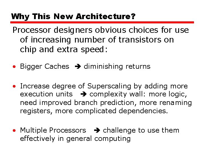
Why This New Architecture? Processor designers obvious choices for use of increasing number of transistors on chip and extra speed: • Bigger Caches diminishing returns • Increase degree of Superscaling by adding more execution units complexity wall: more logic, need improved branch prediction, more renaming registers, more complicated dependencies. • Multiple Processors challenge to use them effectively in general computing
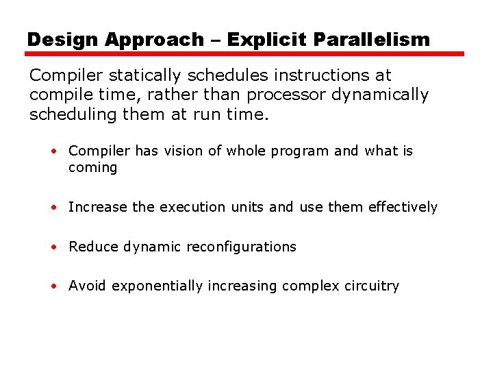
Design Approach – Explicit Parallelism Compiler statically schedules instructions at compile time, rather than processor dynamically scheduling them at run time. • Compiler has vision of whole program and what is coming • Increase the execution units and use them effectively • Reduce dynamic reconfigurations • Avoid exponentially increasing complex circuitry
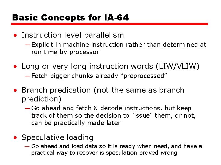
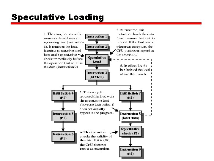
Basic Concepts for IA-64 • Instruction level parallelism — Explicit in machine instruction rather than determined at run time by processor • Long or very long instruction words (LIW/VLIW) — Fetch bigger chunks already “preprocessed” • Branch predication (not the same as branch prediction) — Go ahead and fetch & decode instructions, but keep track of them so the decision to “issue” them, or not, can be practically made later • Speculative loading — Go ahead and load data so it is ready when need, and have a practical way to recover is speculation proved wrong
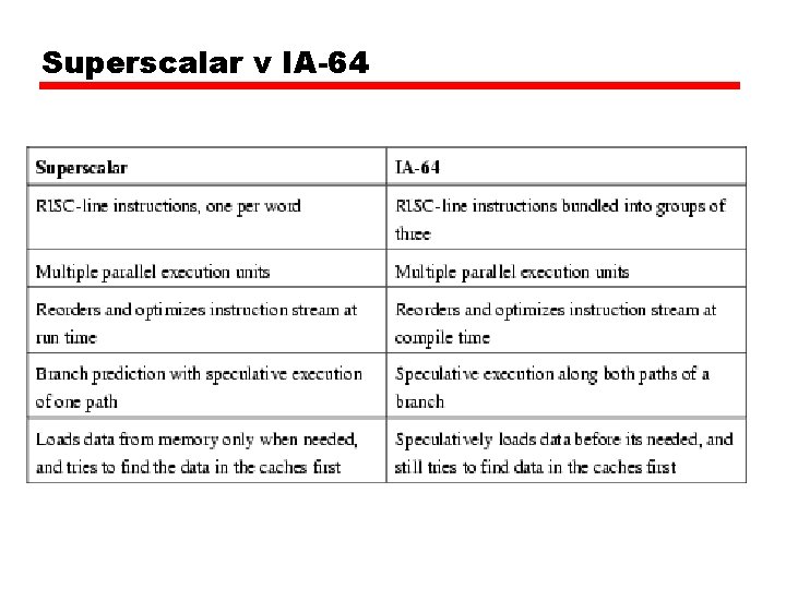
Superscalar v IA-64
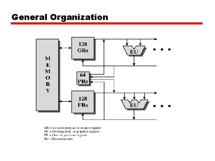
General Organization
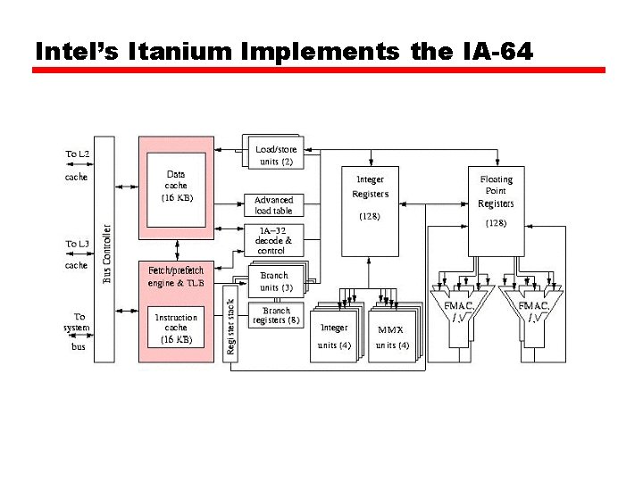
Intel’s Itanium Implements the IA-64
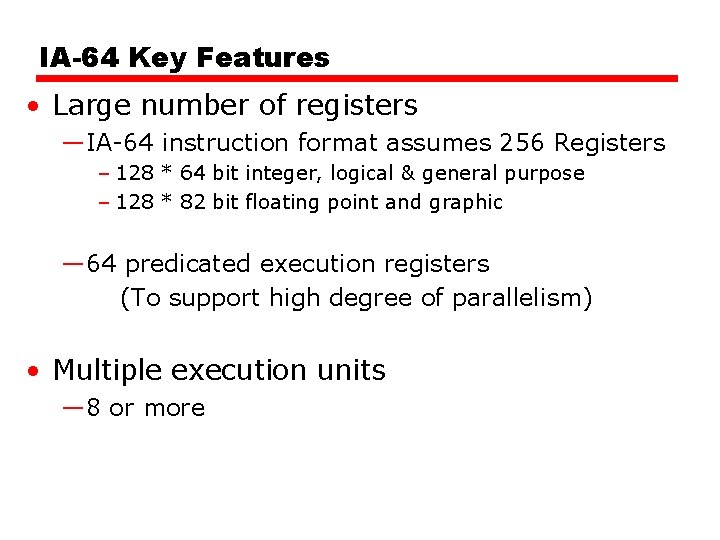
IA-64 Key Features • Large number of registers —IA-64 instruction format assumes 256 Registers – 128 * 64 bit integer, logical & general purpose – 128 * 82 bit floating point and graphic — 64 predicated execution registers (To support high degree of parallelism) • Multiple execution units — 8 or more
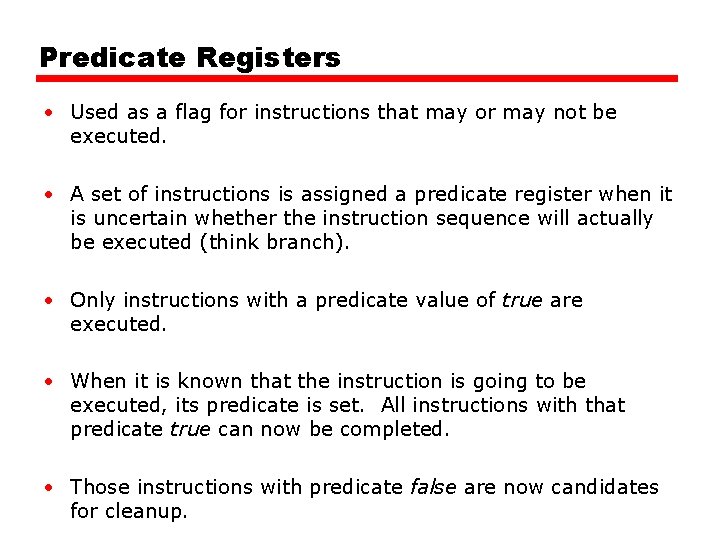
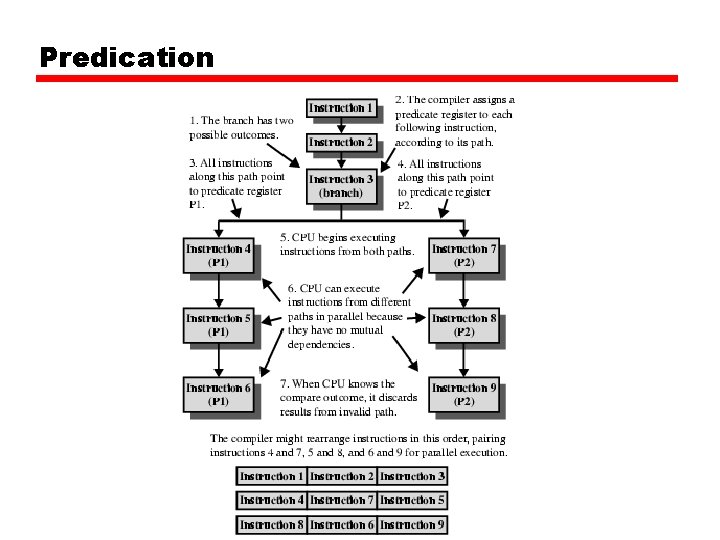
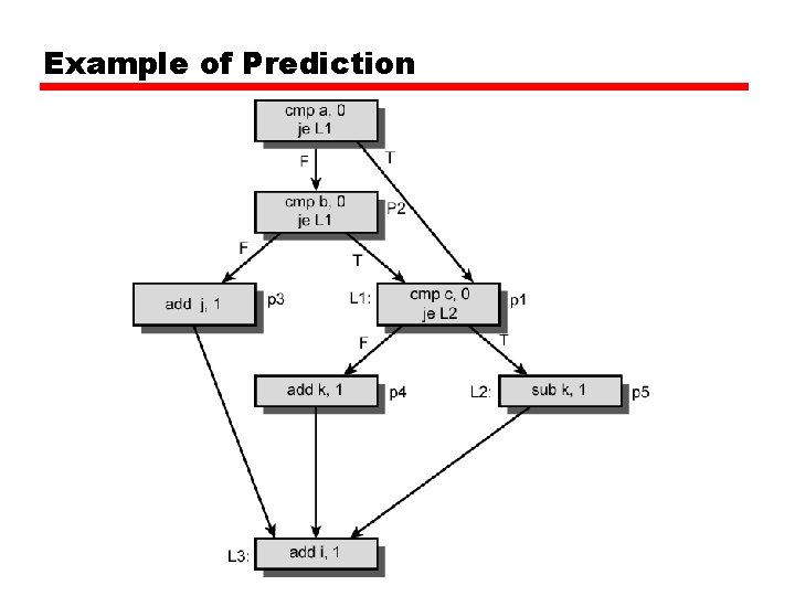
Predicate Registers • Used as a flag for instructions that may or may not be executed. • A set of instructions is assigned a predicate register when it is uncertain whether the instruction sequence will actually be executed (think branch). • Only instructions with a predicate value of true are executed. • When it is known that the instruction is going to be executed, its predicate is set. All instructions with that predicate true can now be completed. • Those instructions with predicate false are now candidates for cleanup.
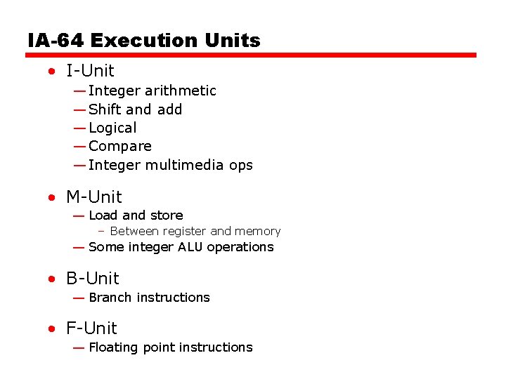
IA-64 Execution Units • I-Unit — Integer arithmetic — Shift and add — Logical — Compare — Integer multimedia ops • M-Unit — Load and store – Between register and memory — Some integer ALU operations • B-Unit — Branch instructions • F-Unit — Floating point instructions
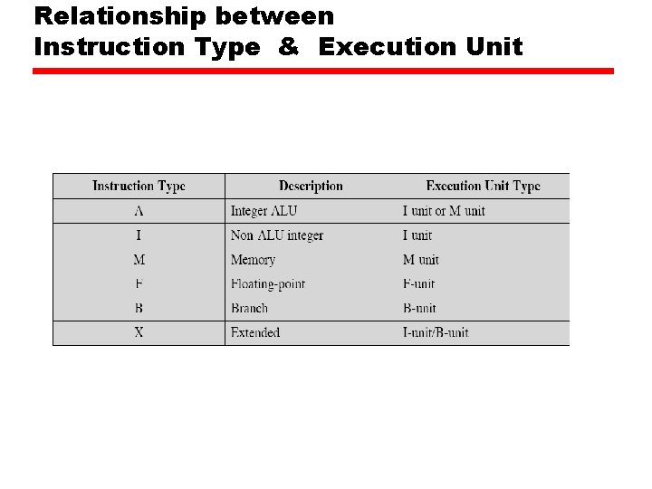
Relationship between Instruction Type & Execution Unit
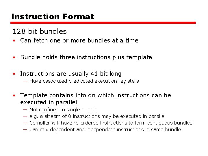
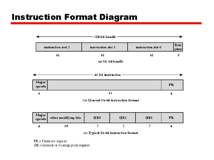
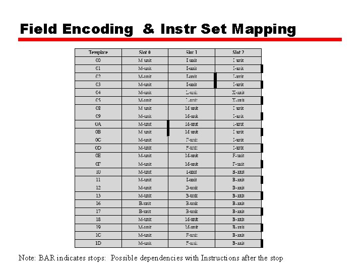
Instruction Format 128 bit bundles • Can fetch one or more bundles at a time • Bundle holds three instructions plus template • Instructions are usually 41 bit long — Have associated predicated execution registers • Template contains info on which instructions can be executed in parallel — — Not confined to single bundle e. g. a stream of 8 instructions may be executed in parallel Compiler will have re-ordered instructions to form contiguous bundles Can mix dependent and independent instructions in same bundle
Instruction Format Diagram
Field Encoding & Instr Set Mapping Note: BAR indicates stops: Possible dependencies with Instructions after the stop
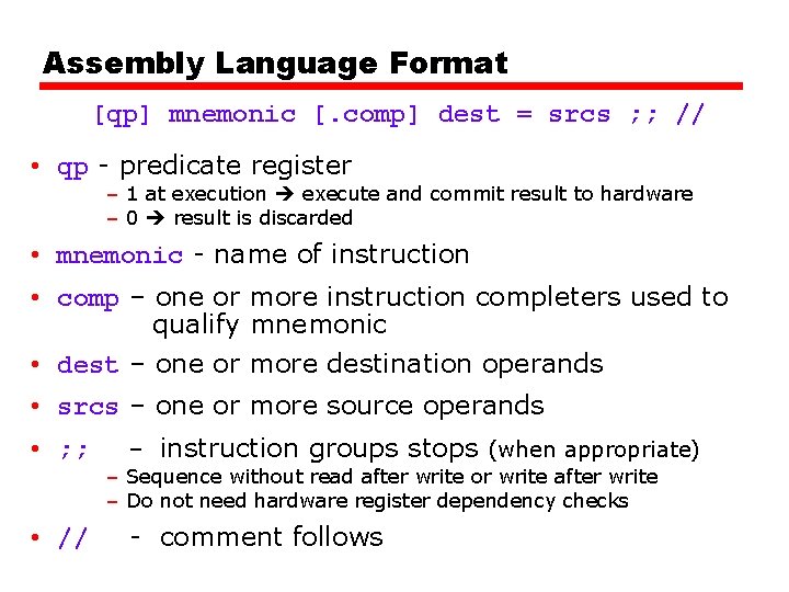
Assembly Language Format [qp] mnemonic [. comp] dest = srcs ; ; // • qp - predicate register – 1 at execution execute and commit result to hardware – 0 result is discarded • mnemonic - name of instruction • comp – one or more instruction completers used to qualify mnemonic • dest – one or more destination operands • srcs – one or more source operands • ; ; • // - instruction groups stops (when appropriate) – Sequence without read after write or write after write – Do not need hardware register dependency checks - comment follows
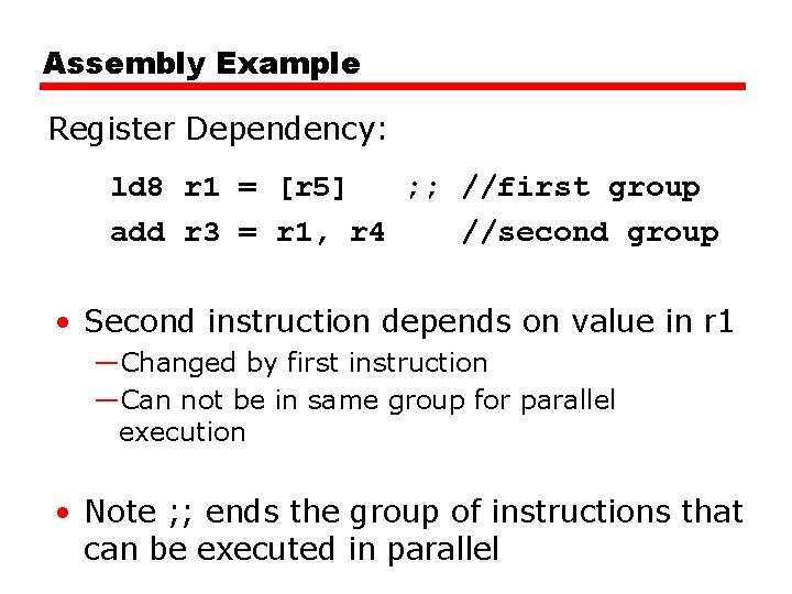
Assembly Example Register Dependency: ld 8 r 1 = [r 5] ; ; //first group add r 3 = r 1, r 4 //second group • Second instruction depends on value in r 1 —Changed by first instruction —Can not be in same group for parallel execution • Note ; ; ends the group of instructions that can be executed in parallel
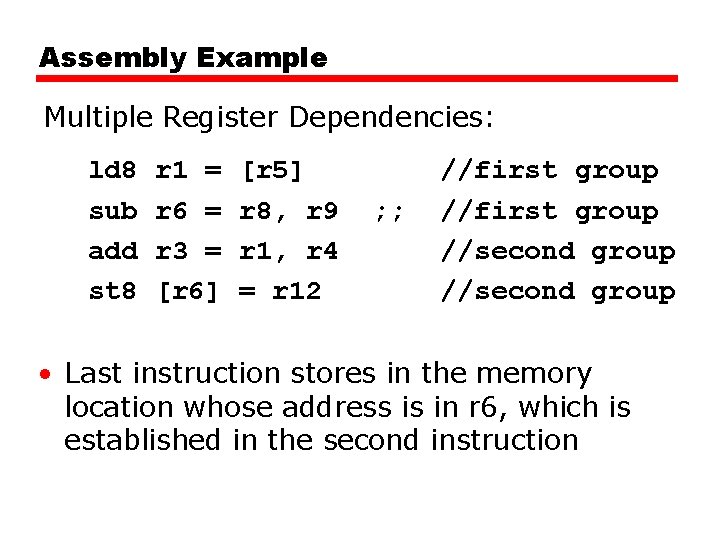
Assembly Example Multiple Register Dependencies: ld 8 sub add st 8 r 1 = r 6 = r 3 = [r 6] [r 5] r 8, r 9 r 1, r 4 = r 12 ; ; //first group //second group • Last instruction stores in the memory location whose address is in r 6, which is established in the second instruction
Predication
Speculative Loading
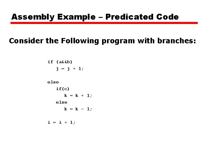
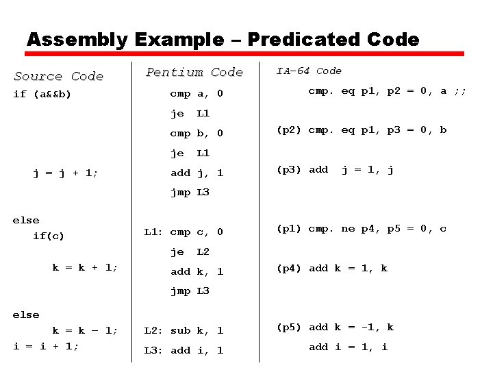
Assembly Example – Predicated Code Consider the Following program with branches: if (a&&b) j = j + 1; else if(c) k = k + 1; else k = k – 1; i = i + 1;
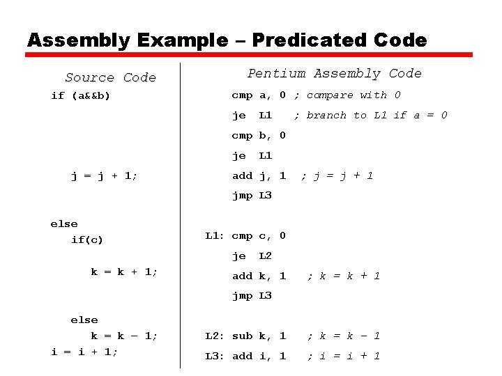
Assembly Example – Predicated Code Pentium Assembly Code Source Code if (a&&b) cmp a, 0 ; compare with 0 je L 1 ; branch to L 1 if a = 0 cmp b, 0 je j = j + 1; L 1 add j, 1 ; j = j + 1 jmp L 3 else if(c) L 1: cmp c, 0 je k = k + 1; L 2 add k, 1 ; k = k + 1 jmp L 3 else k = k – 1; i = i + 1; L 2: sub k, 1 ; k = k – 1 L 3: add i, 1 ; i = i + 1
Assembly Example – Predicated Code Source Code if (a&&b) Pentium Code cmp a, 0 je j = j + 1; cmp. eq p 1, p 2 = 0, a ; ; L 1 cmp b, 0 je IA-64 Code (p 2) cmp. eq p 1, p 3 = 0, b L 1 add j, 1 (p 3) add j = 1, j jmp L 3 else if(c) L 1: cmp c, 0 je k = k + 1; (p 1) cmp. ne p 4, p 5 = 0, c L 2 add k, 1 (p 4) add k = 1, k jmp L 3 else k = k – 1; i = i + 1; L 2: sub k, 1 L 3: add i, 1 (p 5) add k = -1, k add i = 1, i
Example of Prediction
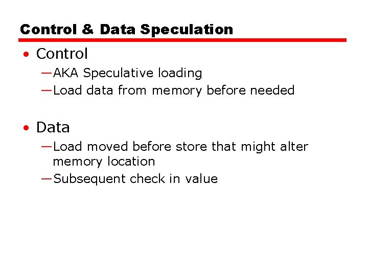
Control & Data Speculation • Control —AKA Speculative loading —Load data from memory before needed • Data —Load moved before store that might alter memory location —Subsequent check in value
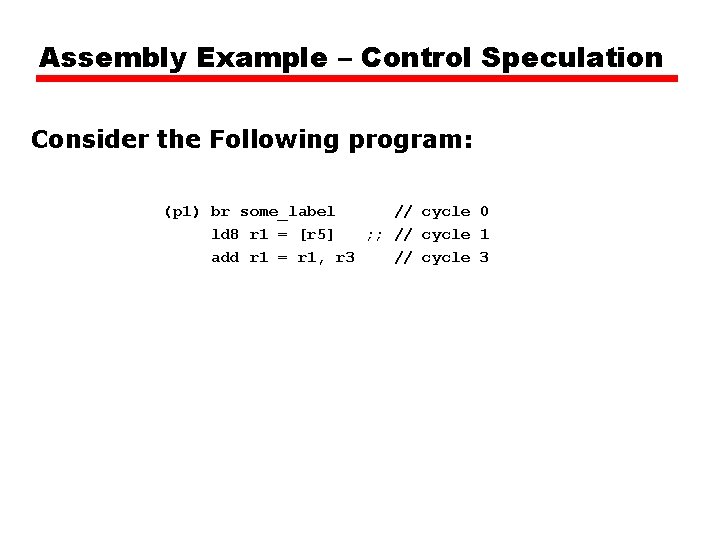
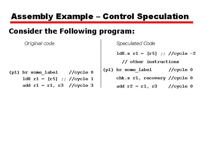
Assembly Example – Control Speculation Consider the Following program: (p 1) br some_label // cycle 0 ld 8 r 1 = [r 5] ; ; // cycle 1 add r 1 = r 1, r 3 // cycle 3
Assembly Example – Control Speculation Consider the Following program: Original code Speculated Code ld 8. s r 1 = [r 5] ; ; //cycle -2 // other instructions (p 1) br some_label //cycle 0 ld 8 r 1 = [r 5] ; ; //cycle 1 add r 1 = r 1, r 3 //cycle 3 (p 1) br some_label //cycle 0 chk. s r 1, recovery //cycle 0 add r 2 = r 1, r 3 //cycle 0
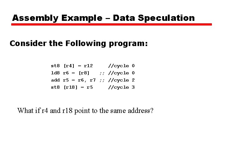
Assembly Example – Data Speculation Consider the Following program: st 8 ld 8 add st 8 [r 4] = r 12 //cycle 0 r 6 = [r 8] ; ; //cycle 0 r 5 = r 6, r 7 ; ; //cycle 2 [r 18] = r 5 //cycle 3 What if r 4 and r 18 point to the same address?
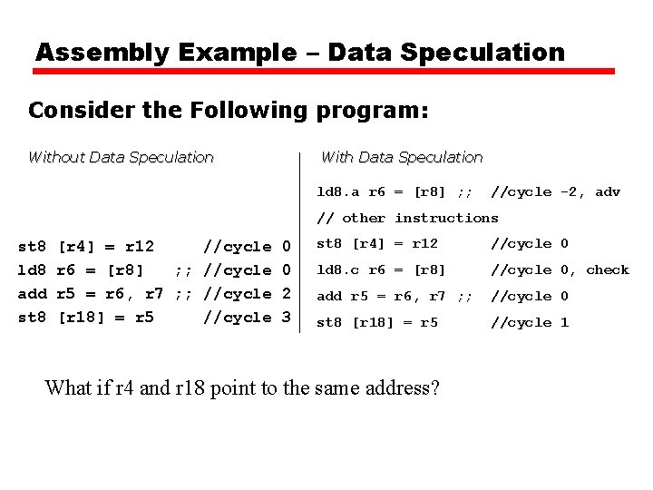
Assembly Example – Data Speculation Consider the Following program: Without Data Speculation With Data Speculation ld 8. a r 6 = [r 8] ; ; //cycle -2, adv // other instructions st 8 ld 8 add st 8 [r 4] = r 12 //cycle 0 r 6 = [r 8] ; ; //cycle 0 r 5 = r 6, r 7 ; ; //cycle 2 [r 18] = r 5 //cycle 3 st 8 [r 4] = r 12 //cycle 0 ld 8. c r 6 = [r 8] //cycle 0, check add r 5 = r 6, r 7 ; ; //cycle 0 st 8 [r 18] = r 5 //cycle 1 What if r 4 and r 18 point to the same address?
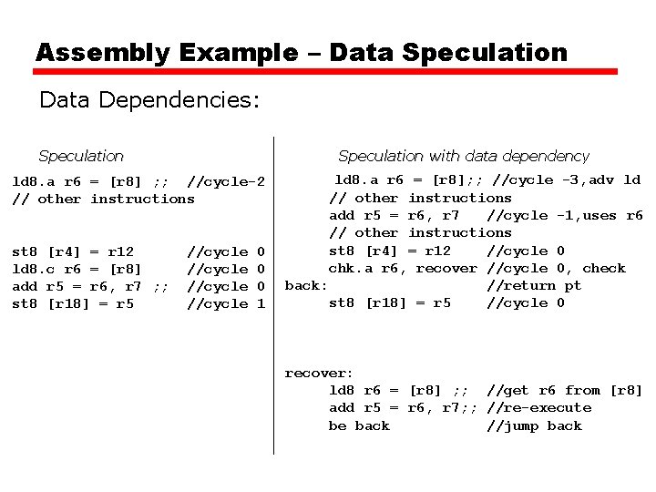
Assembly Example – Data Speculation Data Dependencies: Speculation with data dependency ld 8. a r 6 = [r 8] ; ; //cycle-2 // other instructions st 8 [r 4] = r 12 ld 8. c r 6 = [r 8] add r 5 = r 6, r 7 ; ; st 8 [r 18] = r 5 //cycle 0 0 0 1 ld 8. a r 6 = [r 8]; ; //cycle -3, adv ld // other instructions add r 5 = r 6, r 7 //cycle -1, uses r 6 // other instructions st 8 [r 4] = r 12 //cycle 0 chk. a r 6, recover //cycle 0, check back: //return pt st 8 [r 18] = r 5 //cycle 0 recover: ld 8 r 6 = [r 8] ; ; //get r 6 from [r 8] add r 5 = r 6, r 7; ; //re-execute be back //jump back
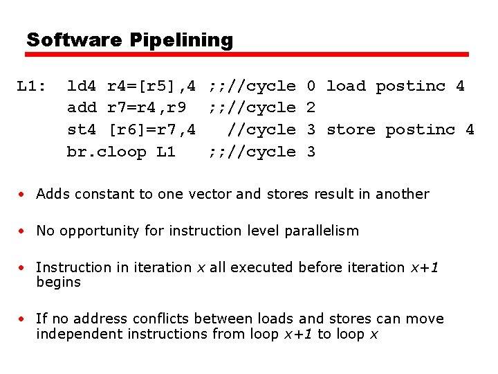
Software Pipelining L 1: ld 4 r 4=[r 5], 4 ; ; //cycle 0 load postinc 4 add r 7=r 4, r 9 ; ; //cycle 2 st 4 [r 6]=r 7, 4 //cycle 3 store postinc 4 br. cloop L 1 ; ; //cycle 3 • Adds constant to one vector and stores result in another • No opportunity for instruction level parallelism • Instruction in iteration x all executed before iteration x+1 begins • If no address conflicts between loads and stores can move independent instructions from loop x+1 to loop x
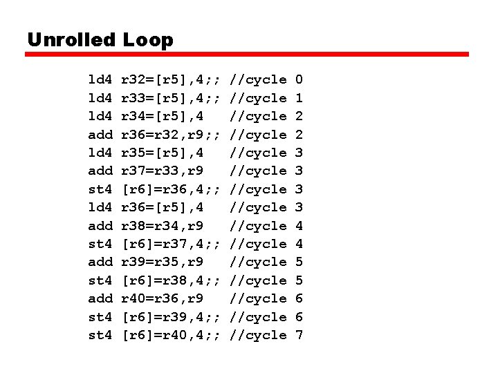
Unrolled Loop ld 4 add st 4 ld 4 add st 4 r 32=[r 5], 4; ; r 33=[r 5], 4; ; r 34=[r 5], 4 r 36=r 32, r 9; ; r 35=[r 5], 4 r 37=r 33, r 9 [r 6]=r 36, 4; ; r 36=[r 5], 4 r 38=r 34, r 9 [r 6]=r 37, 4; ; r 39=r 35, r 9 [r 6]=r 38, 4; ; r 40=r 36, r 9 [r 6]=r 39, 4; ; [r 6]=r 40, 4; ; //cycle //cycle //cycle //cycle 0 1 2 2 3 3 4 4 5 5 6 6 7
Unrolled Loop Detail • Completes 5 iterations in 7 cycles —Compared with 20 cycles in original code • Assumes two memory ports —Load and store can be done in parallel
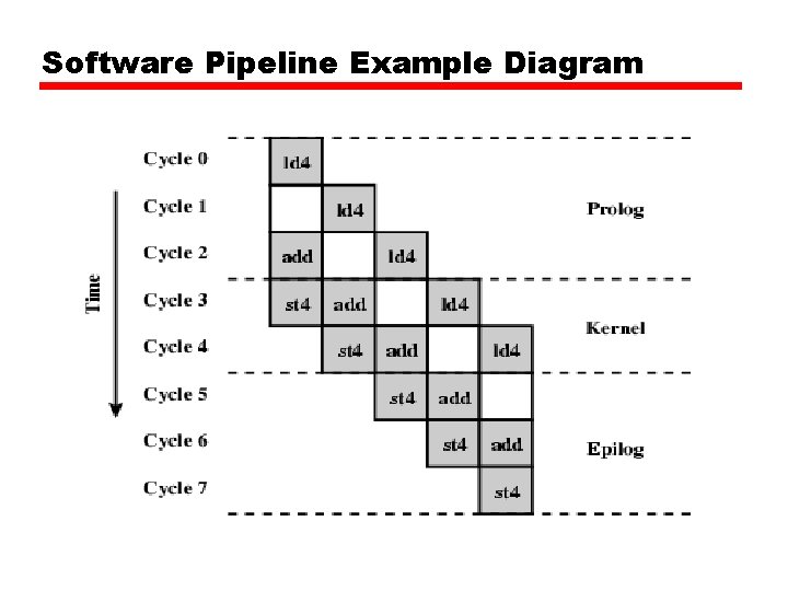
Software Pipeline Example Diagram
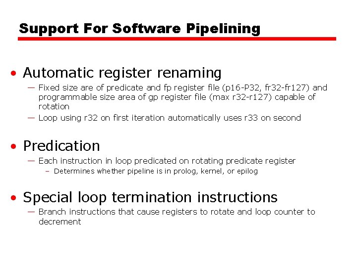
Support For Software Pipelining • Automatic register renaming — Fixed size are of predicate and fp register file (p 16 -P 32, fr 32 -fr 127) and programmable size area of gp register file (max r 32 -r 127) capable of rotation — Loop using r 32 on first iteration automatically uses r 33 on second • Predication — Each instruction in loop predicated on rotating predicate register – Determines whether pipeline is in prolog, kernel, or epilog • Special loop termination instructions — Branch instructions that cause registers to rotate and loop counter to decrement
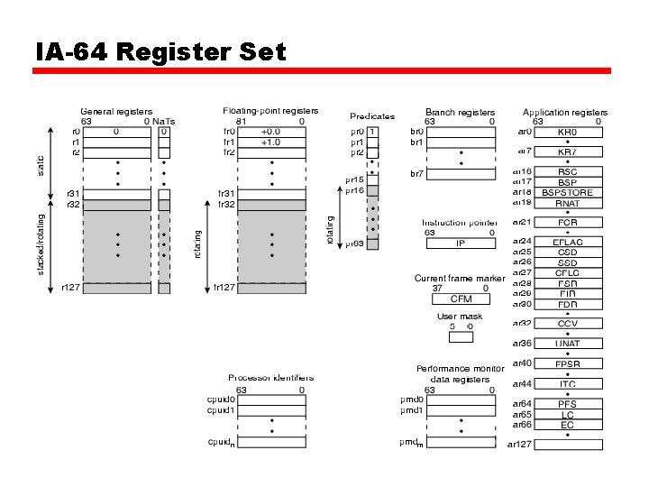
IA-64 Register Set
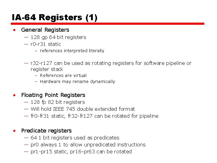
IA-64 Registers (1) • General Registers — 128 gp 64 bit registers — r 0 -r 31 static – references interpreted literally — r 32 -r 127 can be used as rotating registers for software pipeline or register stack – References are virtual – Hardware may rename dynamically • Floating Point Registers — 128 fp 82 bit registers — Will hold IEEE 745 double extended format — fr 0 -fr 31 static, fr 32 -fr 127 can be rotated for pipeline • Predicate registers — 64 1 bit registers used as predicates — pr 0 always 1 to allow unpredicated instructions — pr 1 -pr 15 static, pr 16 -pr 63 can be rotated
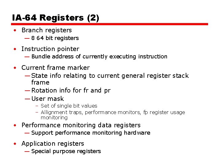
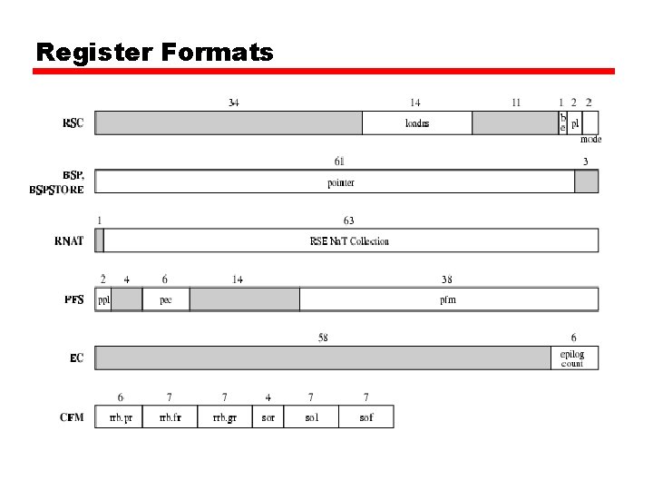
IA-64 Registers (2) • Branch registers — 8 64 bit registers • Instruction pointer — Bundle address of currently executing instruction • Current frame marker — State info relating to current general register stack frame — Rotation info for fr and pr — User mask – Set of single bit values – Allignment traps, performance monitors, fp register usage monitoring • Performance monitoring data registers — Support performance monitoring hardware • Application registers — Special purpose registers
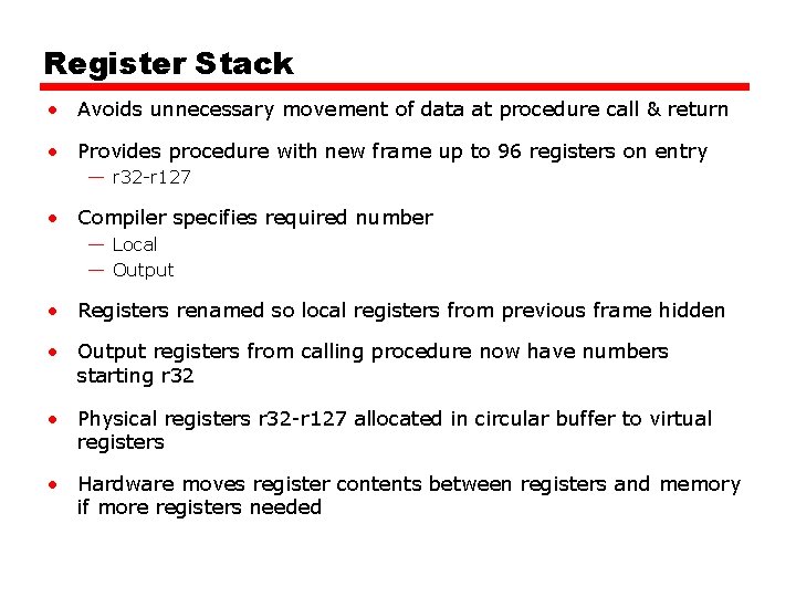
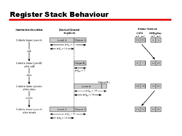
Register Stack • Avoids unnecessary movement of data at procedure call & return • Provides procedure with new frame up to 96 registers on entry — r 32 -r 127 • Compiler specifies required number — Local — Output • Registers renamed so local registers from previous frame hidden • Output registers from calling procedure now have numbers starting r 32 • Physical registers r 32 -r 127 allocated in circular buffer to virtual registers • Hardware moves register contents between registers and memory if more registers needed
Register Stack Behaviour
Register Formats