
Chapter 15 Capacitive AC Circuits Objectives After completing
Chapter 15 Capacitive AC Circuits
Objectives • After completing this chapter, you will be able to: – Describe the phase relationship between current and voltage in a capacitive AC circuit – Determine the capacitive reactance in an AC capacitive circuit
Objectives (cont’d. ) – Describe how resistor-capacitor networks can be used for filtering, coupling, and phase shifting – Explain how low-pass and high-pass RC filters operate
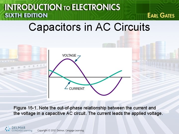
Capacitors in AC Circuits Figure 15 -1. Note the out-of-phase relationship between the current and the voltage in a capacitive AC circuit. The current leads the applied voltage.

Capacitors in AC Circuits (cont’d. ) • Capacitive reactance – Opposition a capacitor offers to the applied AC voltage – Represented by Xc – Measured in ohms
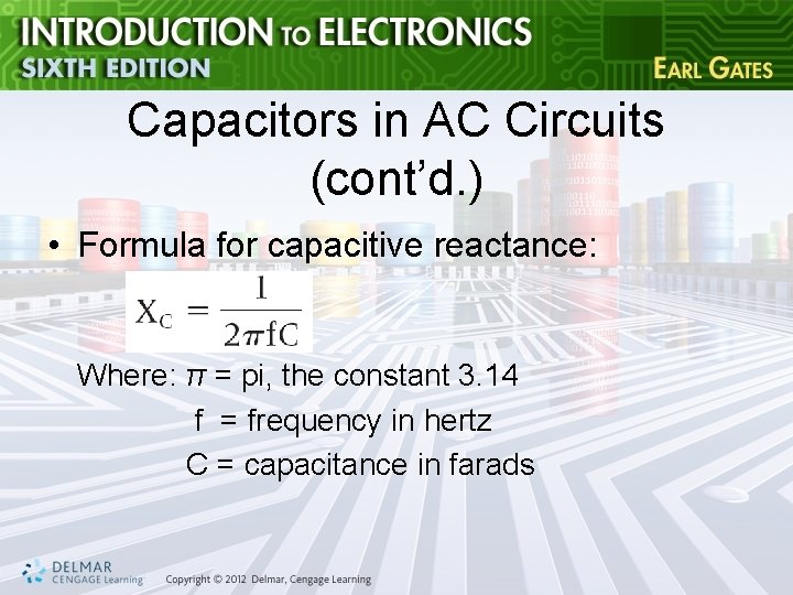
Capacitors in AC Circuits (cont’d. ) • Formula for capacitive reactance: Where: π = pi, the constant 3. 14 f = frequency in hertz C = capacitance in farads
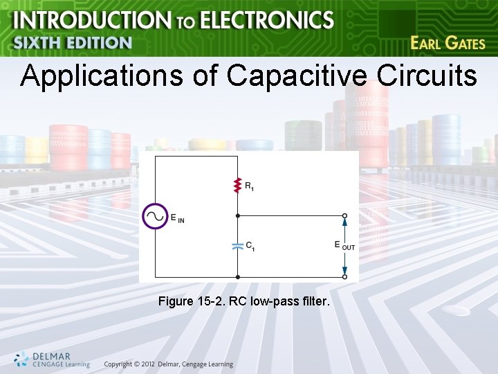
Applications of Capacitive Circuits Figure 15 -2. RC low-pass filter.
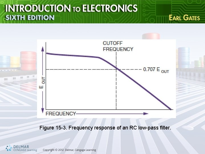
Figure 15 -3. Frequency response of an RC low-pass filter.
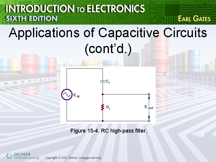
Applications of Capacitive Circuits (cont’d. ) Figure 15 -4. RC high-pass filter.
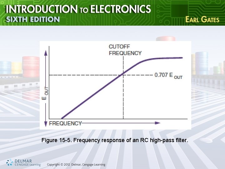
Figure 15 -5. Frequency response of an RC high-pass filter.
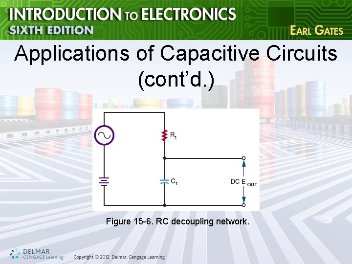
Applications of Capacitive Circuits (cont’d. ) Figure 15 -6. RC decoupling network.
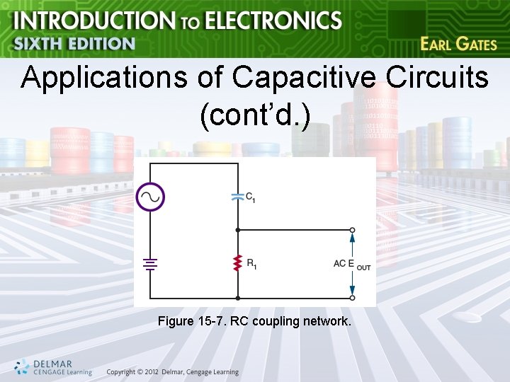
Applications of Capacitive Circuits (cont’d. ) Figure 15 -7. RC coupling network.
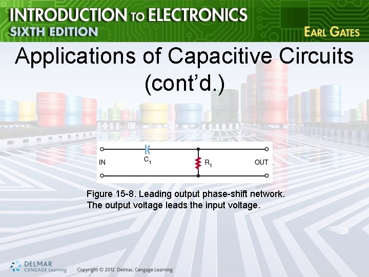
Applications of Capacitive Circuits (cont’d. ) Figure 15 -8. Leading output phase-shift network. The output voltage leads the input voltage.
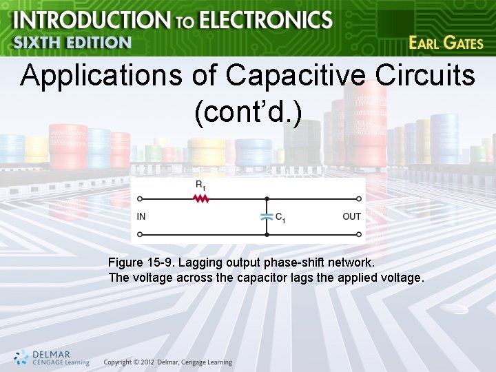
Applications of Capacitive Circuits (cont’d. ) Figure 15 -9. Lagging output phase-shift network. The voltage across the capacitor lags the applied voltage.
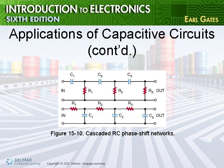
Applications of Capacitive Circuits (cont’d. ) Figure 15 -10. Cascaded RC phase-shift networks.
Summary • When an AC voltage is applied to a capacitor, it gives the appearance of current flow • The capacitor charging and discharging represents current flow • The current leads the applied voltage by 90 degrees in a capacitive circuit
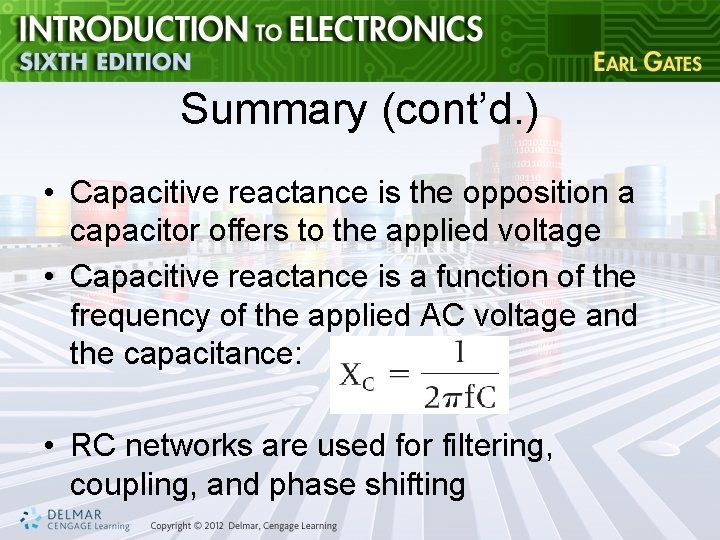
Summary (cont’d. ) • Capacitive reactance is the opposition a capacitor offers to the applied voltage • Capacitive reactance is a function of the frequency of the applied AC voltage and the capacitance: • RC networks are used for filtering, coupling, and phase shifting
- Slides: 17