CHAPTER 14 The Internet Protocol Connectionless Operation Internetworking


 v 4 Ø Defined in RFC 791 Ø Part of TCP/IP")


 Dotted decimal and binary")
 Ø RFC 792 Ø Provides a means for transferring")

 Need MAC address to send to LAN host Manual Included")
 wastes")


- Slides: 41
CHAPTER 14 The Internet Protocol
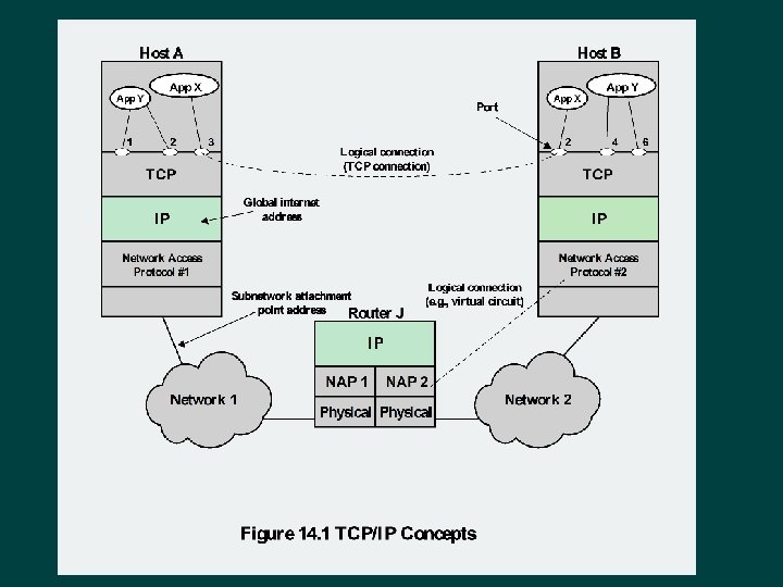
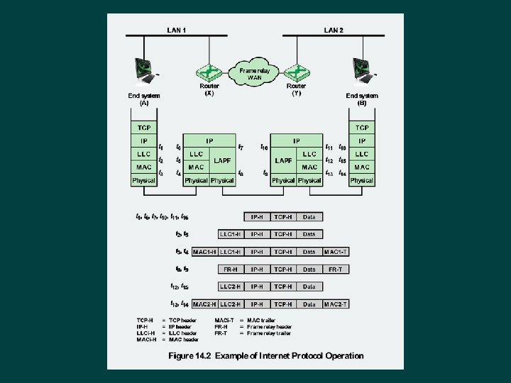
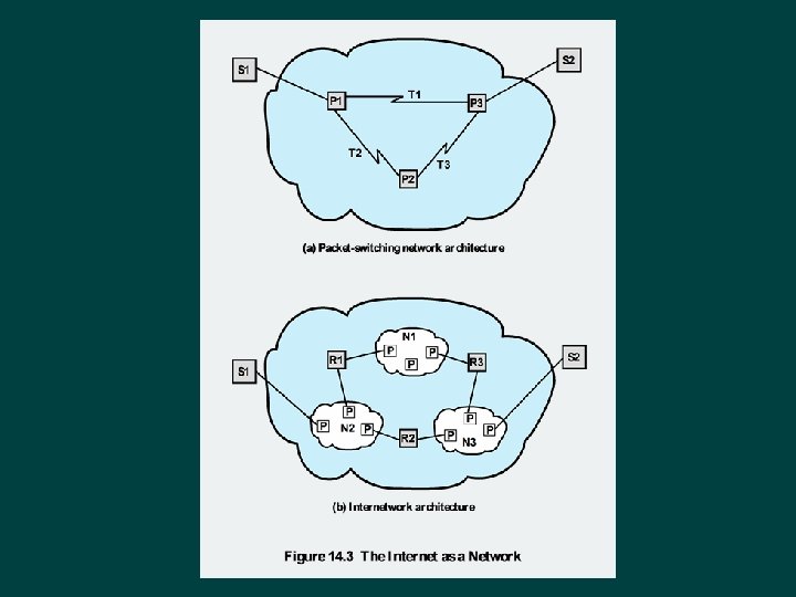
Connectionless Operation Ø Internetworking involves connectionless operation at the level of the Internet Protocol (IP) IP • Initially developed for the DARPA internet project • Protocol is needed to access a particular network
Connectionless Internetworking Ø Connectionless internet facility is flexible Ø IP provides a connectionless service between end systems l Advantages: • • • Is flexible Can be made robust Does not impose unnecessary overhead
IP Design Issues Ø Routing Ø Datagram lifetime Ø Fragmentation and reassembly Ø Error control Ø Flow control
Routing • Routing table indicates next router to which datagram is sent • Can be static or dynamic ES / routers maintain routing tables Source routing • Source specifies route to be followed • Can be useful for security and priority • Each router appends its internet address to a list of addresses in the datagram • Useful for testing and debugging purposes Route recording
Datagram Lifetime Ø If dynamic or alternate routing is used the potential exists for a datagram to loop indefinitely l l Consumes resources Transport protocol may need upper bound on lifetime of a datagram • Can mark datagram with lifetime • When lifetime expires, datagram is discarded
Fragmentation and Re-assembly Protocol exchanges data between two entities Ø Lower-level protocols may need to break data up into smaller blocks, called fragmentation Ø Reasons for fragmentation: Ø l l Ø Network only accepts blocks of a certain size More efficient error control and smaller retransmission units Fairer access to shared facilities Smaller buffers Disadvantages: l l Smaller buffers More interrupts and processing time
Fragmentation and Re-assembly At destination Issue of when to re-assemble Packets get smaller as data traverses internet Need large buffers at routers Intermediate re -assembly Buffers may fill with fragments All fragments must go through same router
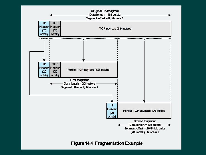
IP Fragmentation IP re-assembles at destination only Ø Uses fields in header Ø Data Unit Identifier (ID) Identifies end system originated datagram Data length Length of user data in octets Offset Position of fragment of user data in original datagram In multiples of 64 bits (8 octets) More flag Indicates that this is not the last fragment
Error and Flow Control Ø Error control l l Discarded datagram identification is needed Reasons for discarded datagrams include: • • • Lifetime expiration Congestion FCS error l l ØFlow control Allows routers to limit the rate they receive data Send flow control packets requesting reduced data flow
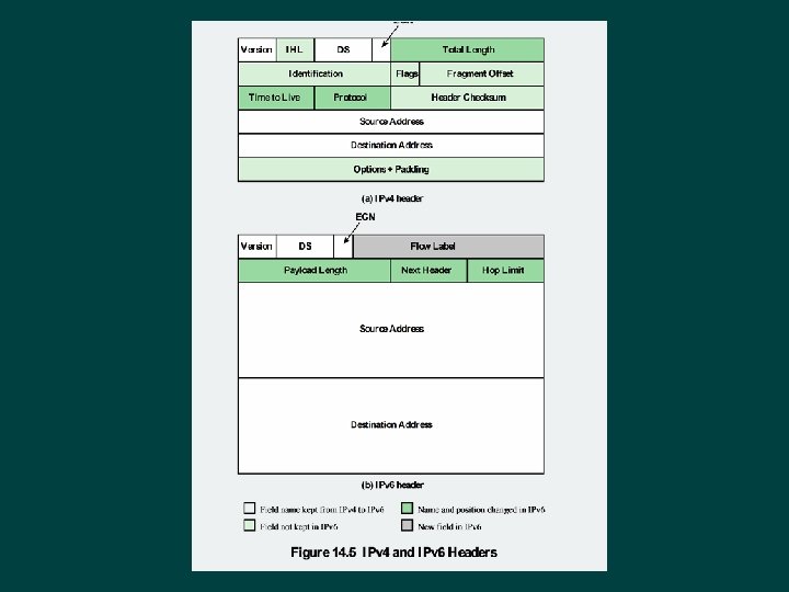
Internet Protocol (IP) v 4 Ø Defined in RFC 791 Ø Part of TCP/IP suite Ø Two parts Specification of interface with a higher layer Specification of actual protocol format and mechanisms
IP Services Ø Primitives l l Specifies functions to be performed Form of primitive implementation dependent Send-request transmission of data unit Deliver-notify user of arrival of data unit Ø Parameters l Used to pass data and control information
IP Parameters Source and destination addresses Ø Protocol Ø Type of Service Ø Identification Ø Don’t fragment indicator Ø Time to live Ø Data length Ø Option data Ø User data Ø
IP Options Route recording Security Source routing Stream identification Timestamping
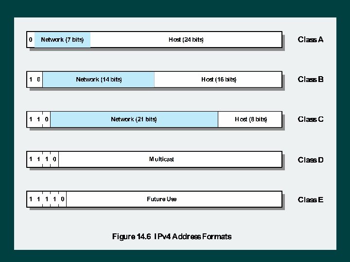
IP Addresses Class A IP Addresses Class B Start with binary 0 Start with binary 110 Range 192 to 223 Network addresses with a first octet of 0 (binary 0000000) and 127 (binary 01111111) are reserved Range 128 to 191(binary 10000000 to 10111111) 126 potential Class A network numbers Second octet also included in network address Range 1 to 126 IP Addresses Class C 214 = 16, 384 Class B addresses Second and third octet also part of network address 221 = 2, 097, 152 addresses Nearly allocated • See IPv 6
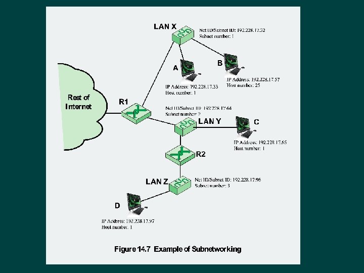
Subnets and Subnet Masks Allows arbitrary complexity of internetworked LANs within organization Ø Insulate overall internet from growth of network numbers and routing complexity Ø Site looks to rest of internet like single network Ø Each LAN assigned subnet number Ø Host portion of address partitioned into subnet number and host number Ø Local routers route within subnetted network Ø Subnet mask indicates which bits are subnet number and which are host number Ø
Table 14. 2 IPv 4 Addresses and Subnet Masks (a) Dotted decimal and binary representations of IPv 4 address and subnet masks (b) Default subnet masks
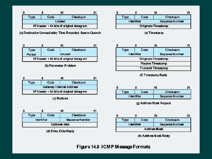
Internet Control Message Protocol (ICMP) Ø RFC 792 Ø Provides a means for transferring messages from routers and other hosts to a host Ø Provides feedback about problems • Datagram cannot reach its destination • Router does not have buffer capacity to forward • Router can send traffic on a shorter route Ø Encapsulated in IP datagram l Hence not reliable
Common ICMP Messages Ø Destination unreachable Ø Time exceeded Ø Parameter problem Ø Source quench Ø Redirect Ø Echo and echo reply Ø Timestamp and timestamp reply Ø Address mask request and reply
Address Resolution Protocol (ARP) Need MAC address to send to LAN host Manual Included in network address Use central directory Use address resolution protocol ARP (RFC 826) provides dynamic IP to Ethernet address mapping Source broadcasts ARP request Destination replies with ARP response
IP Next Generation Address space exhaustion: • Two level addressing (network and host) wastes space • Network addresses used even if not connected • Growth of networks and the Internet • Extended use of TCP/IP • Single address per host Requirements for new types of service • Address configuration • routing flexibility • Traffic support
IPv 6 RFCs Ø RFC 1752 - Recommendations for the IP Next Generation Protocol l Requirements PDU formats Addressing, routing security issues RFC 2460 - overall specification Ø RFC 4291 - addressing structure Ø
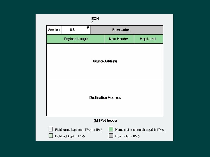
IPv 6 Enhancements Ø Expanded 128 bit address space Ø Improved option mechanism l Most not examined by intermediate routes Ø Dynamic address assignment Ø Increased addressing flexibility l Anycast and multicast Ø Support for resource allocation l Labeled packet flows
IPv 6 Flow Label Related sequence of packets Ø Special handling Ø Identified by source and destination address plus flow label Ø Router treats flow as sharing attributes Ø May treat flows differently Ø Alternative to including all information in every header Ø Have requirements on flow label processing Ø
IPv 6 Addresses 128 bits long Ø Assigned to interface Ø Single interface may have multiple unicast addresses Ø Three types of addresses: • Unicast - single interface address • Anycast - one of a set of interface addresses • Multicast - all of a set of interfaces
Table 14. 3 IPv 6 Address Space Usage
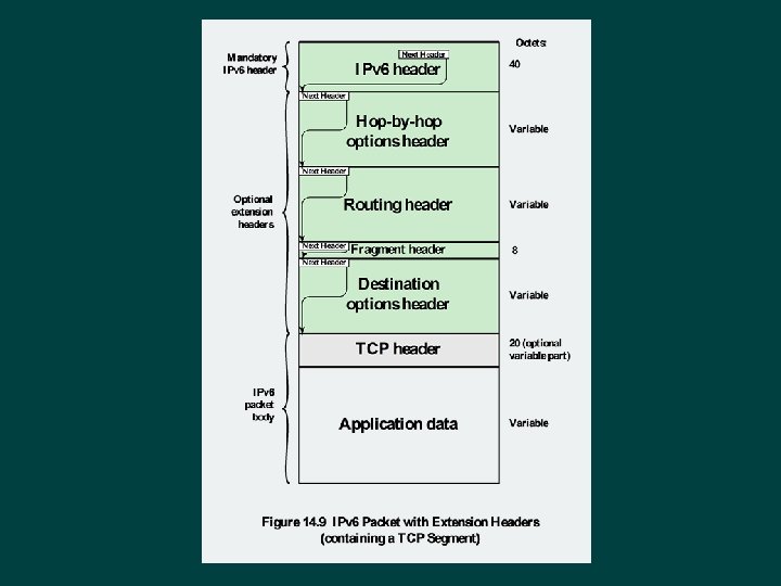
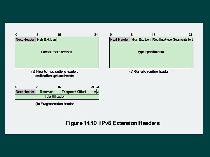
Hop-by-Hop Options Ø Must be examined by every router l If unknown discard/forward handling is specified Next header Ø Header extension length Ø Options Ø l l Pad 1 Pad. N Jumbo payload Router alert
Fragmentation Header Fragmentation only allowed at source Ø No fragmentation at intermediate routers Ø Node must perform path discovery to find smallest MTU of intermediate networks Ø Set source fragments to match MTU Ø Otherwise limit to 1280 octets Ø
Routing Header Ø Contains a list of one or more intermediate nodes to be visited on the way to a packet’s destination Header includes • • Next header Header extension length Routing type Segments left
Destination Options Header Carries optional information for destination node Format same as hop-by-hop header