
Chapter 13 Radiation Heat Transfer Yoav Peles Department
















- Slides: 100
Chapter 13: Radiation Heat Transfer Yoav Peles Department of Mechanical, Aerospace and Nuclear Engineering Rensselaer Polytechnic Institute
Objectives • • • When you finish studying this chapter, you should be able to: Define view factor, and understand its importance in radiation heat transfer calculations, Develop view factor relations, and calculate the unknown view factors in an enclosure by using these relations, Calculate radiation heat transfer between black surfaces, Determine radiation heat transfer between diffuse and gray surfaces in an enclosure using the concept of radiosity, Obtain relations for net rate of radiation heat transfer between the surfaces of a two-zone enclosure, including two large parallel plates, two long concentric cylinders, and two concentric spheres, Quantify the effect of radiation shields on the reduction of radiation heat transfer between two surfaces, and become aware of the importance of radiation effect in temperature measurements.
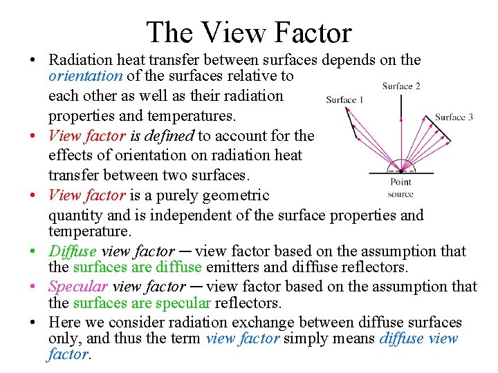
The View Factor • Radiation heat transfer between surfaces depends on the orientation of the surfaces relative to each other as well as their radiation properties and temperatures. • View factor is defined to account for the effects of orientation on radiation heat transfer between two surfaces. • View factor is a purely geometric quantity and is independent of the surface properties and temperature. • Diffuse view factor ─ view factor based on the assumption that the surfaces are diffuse emitters and diffuse reflectors. • Specular view factor ─ view factor based on the assumption that the surfaces are specular reflectors. • Here we consider radiation exchange between diffuse surfaces only, and thus the term view factor simply means diffuse view factor.
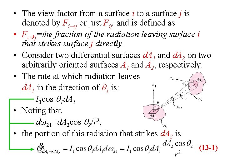
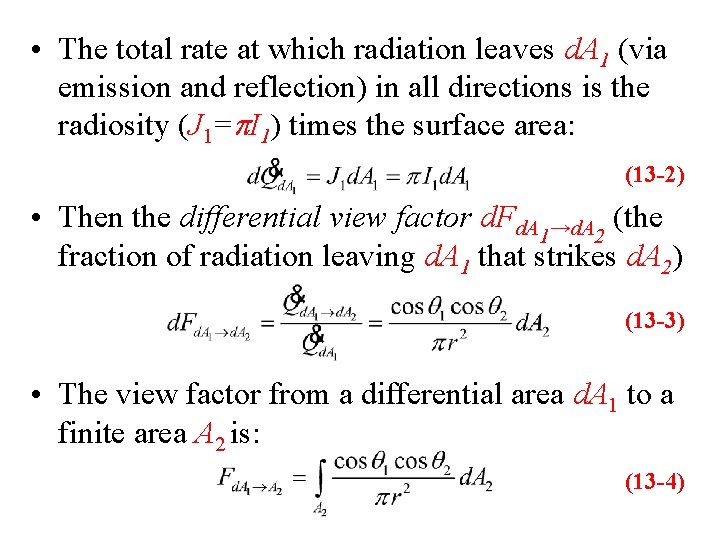
• The view factor from a surface i to a surface j is denoted by Fi→j or just Fij, and is defined as • Fi j=the fraction of the radiation leaving surface i that strikes surface j directly. • Consider two differential surfaces d. A 1 and d. A 2 on two arbitrarily oriented surfaces A 1 and A 2, respectively. • The rate at which radiation leaves d. A 1 in the direction of q 1 is: I 1 cos q 1 d. A 1 • Noting that dw 21=d. A 2 cos q 2/r 2, • the portion of this radiation that strikes d. A 2 is (13 -1)
• The total rate at which radiation leaves d. A 1 (via emission and reflection) in all directions is the radiosity (J 1=p. I 1) times the surface area: (13 -2) • Then the differential view factor d. Fd. A 1→d. A 2 (the fraction of radiation leaving d. A 1 that strikes d. A 2) (13 -3) • The view factor from a differential area d. A 1 to a finite area A 2 is: (13 -4)
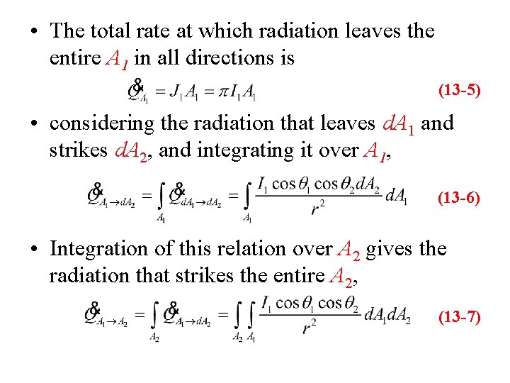
• The total rate at which radiation leaves the entire A 1 in all directions is (13 -5) • considering the radiation that leaves d. A 1 and strikes d. A 2, and integrating it over A 1, (13 -6) • Integration of this relation over A 2 gives the radiation that strikes the entire A 2, (13 -7)
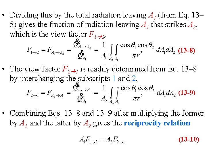
• Dividing this by the total radiation leaving A 1 (from Eq. 13– 5) gives the fraction of radiation leaving A 1 that strikes A 2, which is the view factor F 1 2, (13 -8) • The view factor F 2 1 is readily determined from Eq. 13– 8 by interchanging the subscripts 1 and 2, (13 -9) • Combining Eqs. 13– 8 and 13– 9 after multiplying the former by A 1 and the latter by A 2 gives the reciprocity relation (13 -10)
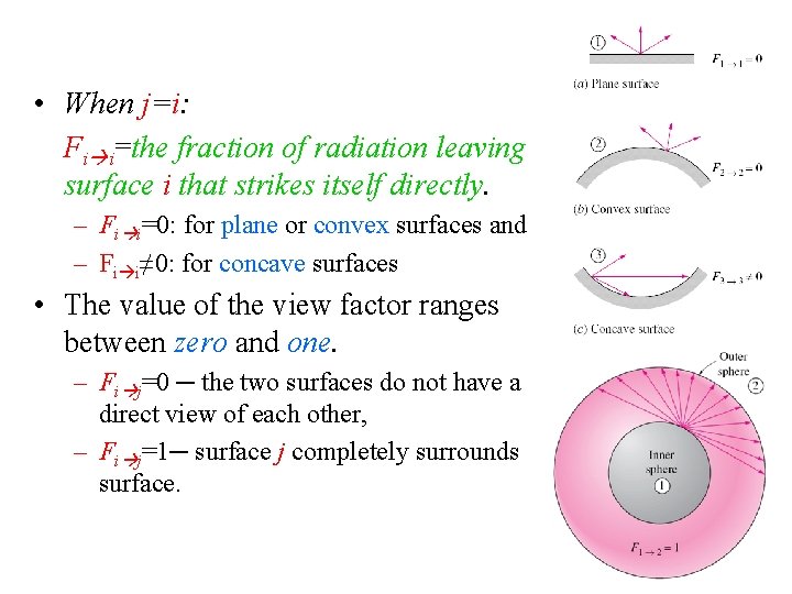
• When j=i: Fi i=the fraction of radiation leaving surface i that strikes itself directly. – Fi i=0: for plane or convex surfaces and – Fi i≠ 0: for concave surfaces • The value of the view factor ranges between zero and one. – Fi j=0 ─ the two surfaces do not have a direct view of each other, – Fi j=1─ surface j completely surrounds surface.
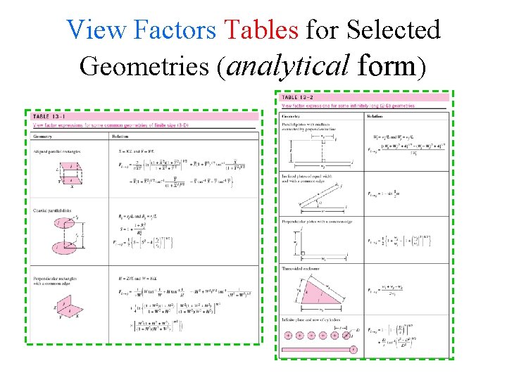
View Factors Tables for Selected Geometries (analytical form)
View Factors Figures for Selected Geometries (graphical form)
View Factor Relations • Radiation analysis on an enclosure consisting of N surfaces requires the evaluation of N 2 view factors. • Fundamental relations for view factors: – the reciprocity relation, – the summation rule, – the superposition rule, – the symmetry rule.
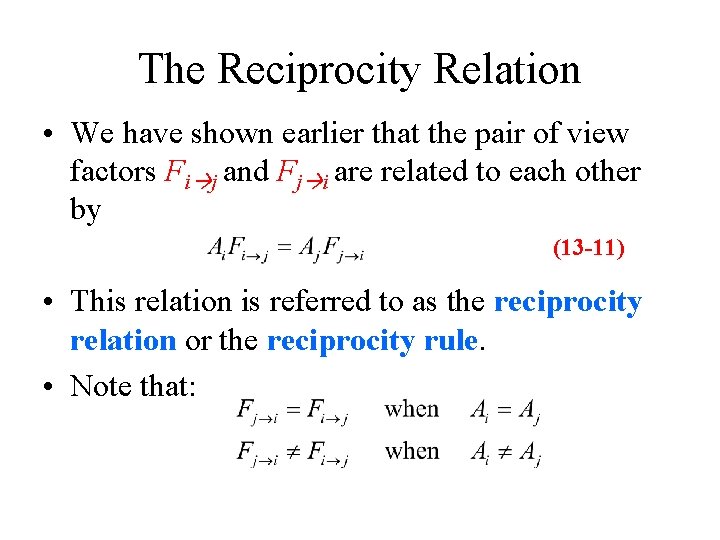
The Reciprocity Relation • We have shown earlier that the pair of view factors Fi j and Fj i are related to each other by (13 -11) • This relation is referred to as the reciprocity relation or the reciprocity rule. • Note that:
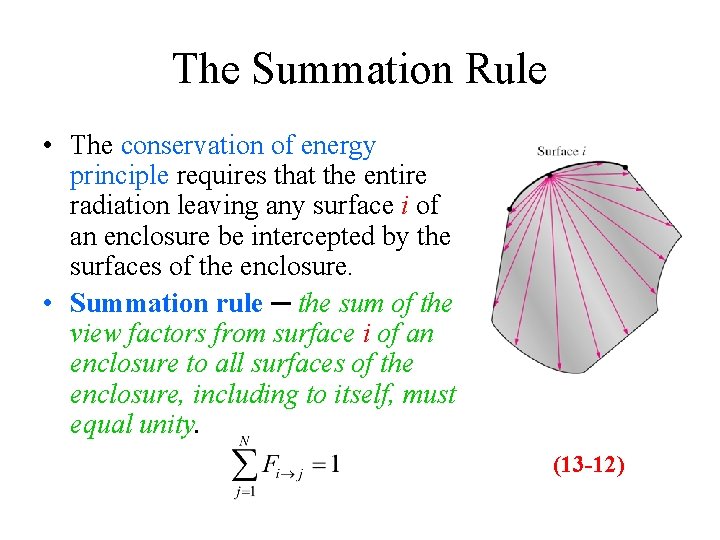
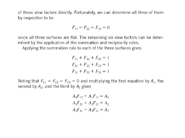
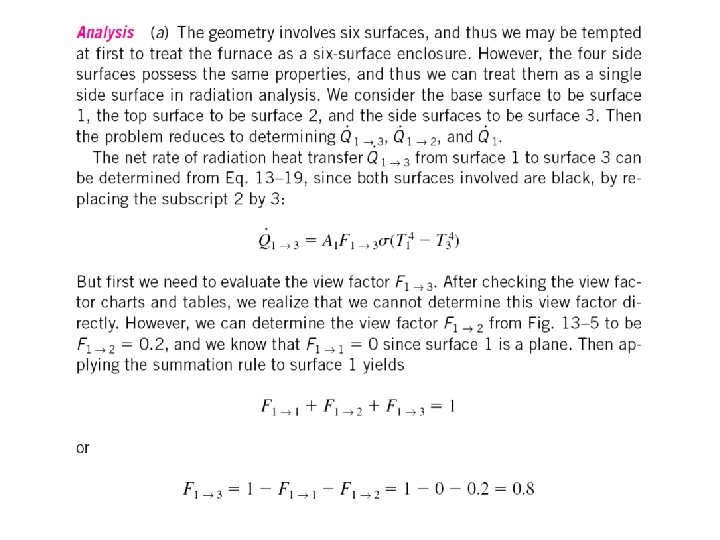
The Summation Rule • The conservation of energy principle requires that the entire radiation leaving any surface i of an enclosure be intercepted by the surfaces of the enclosure. • Summation rule ─ the sum of the view factors from surface i of an enclosure to all surfaces of the enclosure, including to itself, must equal unity. (13 -12)
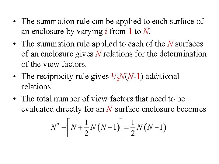
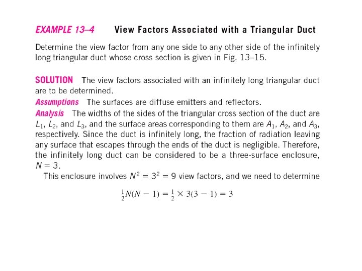
• The summation rule can be applied to each surface of an enclosure by varying i from 1 to N. • The summation rule applied to each of the N surfaces of an enclosure gives N relations for the determination of the view factors. • The reciprocity rule gives 1/2 N(N-1) additional relations. • The total number of view factors that need to be evaluated directly for an N-surface enclosure becomes
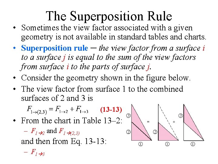
The Superposition Rule • Sometimes the view factor associated with a given geometry is not available in standard tables and charts. • Superposition rule ─ the view factor from a surface i to a surface j is equal to the sum of the view factors from surface i to the parts of surface j. • Consider the geometry shown in the figure below. • The view factor from surface 1 to the combined surfaces of 2 and 3 is (13 -13) • From the chart in Table 13– 2: – F 1 2 and F 1 (2, 3) and then from Eq. 13 -13: – F 1 3
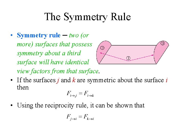
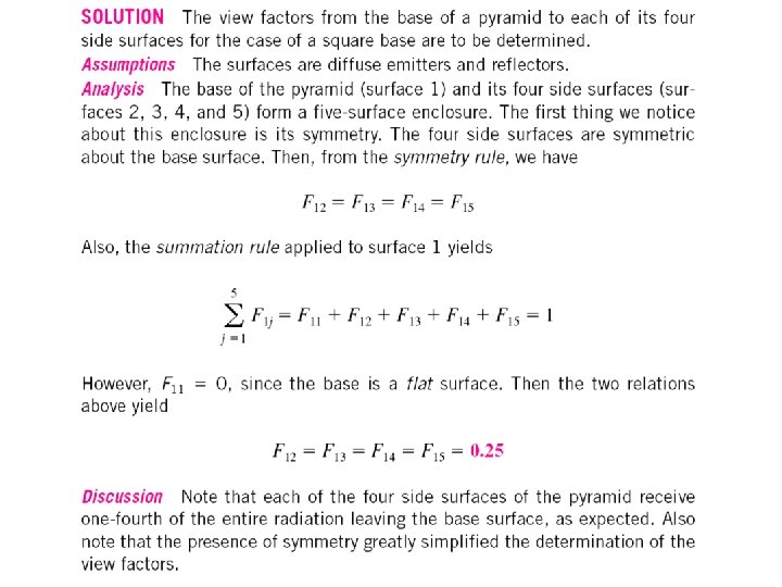
The Symmetry Rule • Symmetry rule ─ two (or more) surfaces that possess symmetry about a third surface will have identical view factors from that surface. • If the surfaces j and k are symmetric about the surface i then • Using the reciprocity rule, it can be shown that
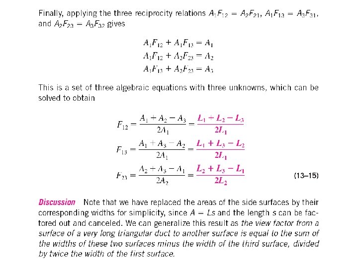
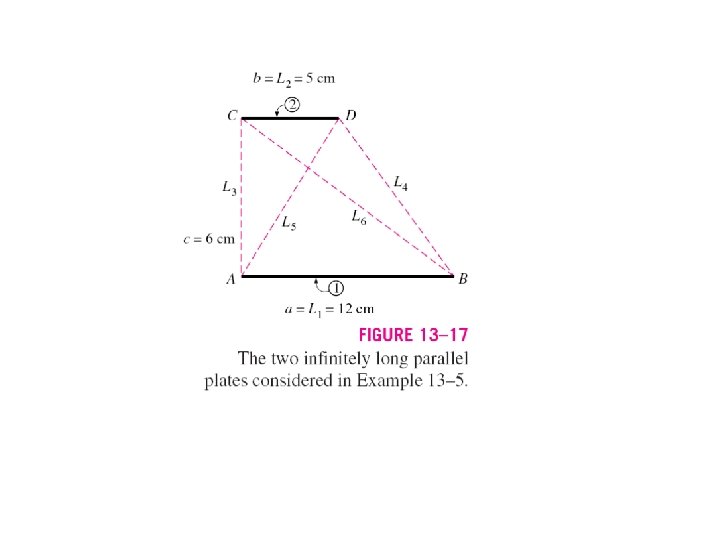
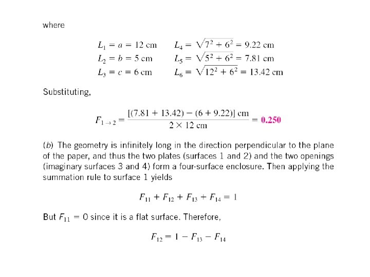
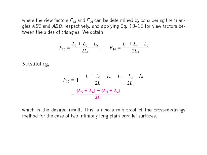
View Factors between Infinitely Long Surfaces: The Crossed-Strings Method • The view factor between two-dimensional surfaces can be determined by the simple crossed-strings method developed by H. C. Hottel in the 1950 s. • Consider the geometry shown in the figure. • Hottel has shown that the view factor F 1 2 can be expressed in terms of the lengths of the stretched strings as (13 -16)
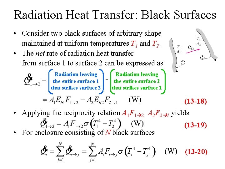
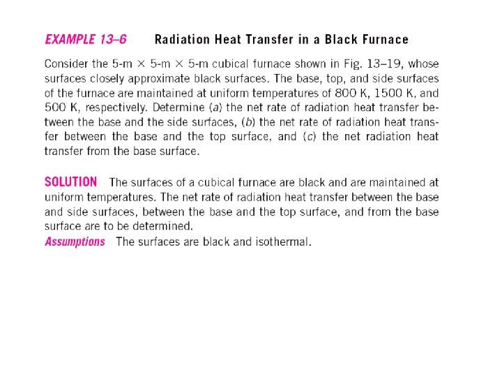
Radiation Heat Transfer: Black Surfaces • Consider two black surfaces of arbitrary shape maintained at uniform temperatures T 1 and T 2. • The net rate of radiation heat transfer from surface 1 to surface 2 can be expressed as = Radiation leaving the entire surface 1 that strikes surface 2 - Radiation leaving the entire surface 2 that strikes surface 1 (13 -18) • Applying the reciprocity relation A 1 F 1 2=A 2 F 2 1 yields • For enclosure consisting of N black surfaces (13 -19) (13 -20)
Radiation Heat Transfer: Diffuse, Gray Surfaces • To make a simple radiation analysis possible, it is common to assume the surfaces of an enclosure are: – opaque (nontransparent), – diffuse (diffuse emitters and diffuse reflectors), – gray (independent of wavelength), – isothermal, and – both the incoming and outgoing radiation are uniform over each surface.
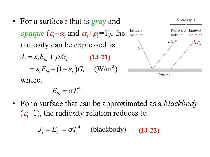
• For a surface i that is gray and opaque (ei=ai and ai+ri=1), the radiosity can be expressed as (13 -21) where: • For a surface that can be approximated as a blackbody (ei=1), the radiosity relation reduces to: (13 -22)
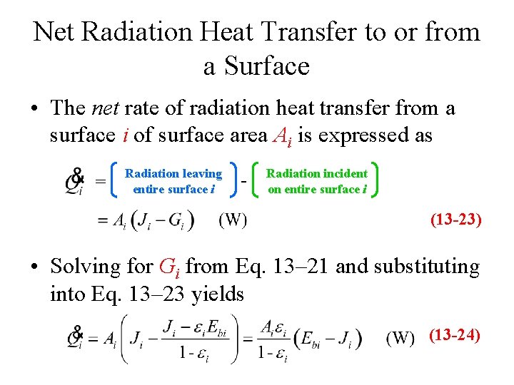
Net Radiation Heat Transfer to or from a Surface • The net rate of radiation heat transfer from a surface i of surface area Ai is expressed as = Radiation leaving entire surface i - Radiation incident on entire surface i (13 -23) • Solving for Gi from Eq. 13– 21 and substituting into Eq. 13– 23 yields (13 -24)
• In an electrical analogy to Ohm’s law, Eq. 13 -24 can be rearranged as (13 -25) where surface resistance to radiation is (13 -26) • For a blackbody Ri=0 and the net rate of radiation heat transfer in this case is determined directly from Eq. 13 – 23.
• Reradiating surface ─ an adiabatic surface: – when convection effects is negligible, – under steady-state conditions. • Reradiating surface must lose as much radiation energy as it gains, thus: Eq. 13 -25 (13 -27) • The temperature of a reradiating surface is independent of its emissivity.
Net Radiation Heat Transfer between Any Two Surfaces • Consider two diffuse, gray, and opaque surfaces of arbitrary shape maintained at uniform temperatures. • The net rate of radiation heat transfer from surface i to surface j can be expressed as = Radiation leaving the entire surface i that strikes surface j - Radiation leaving the entire surface j that strikes surface i (13 -28)
• Applying the reciprocity relation Ai. Fi j= Aj. Fj i yields (13 -29) • In analogy to Ohm’s law (13 -30) where space resistance to radiation is (13 -31)
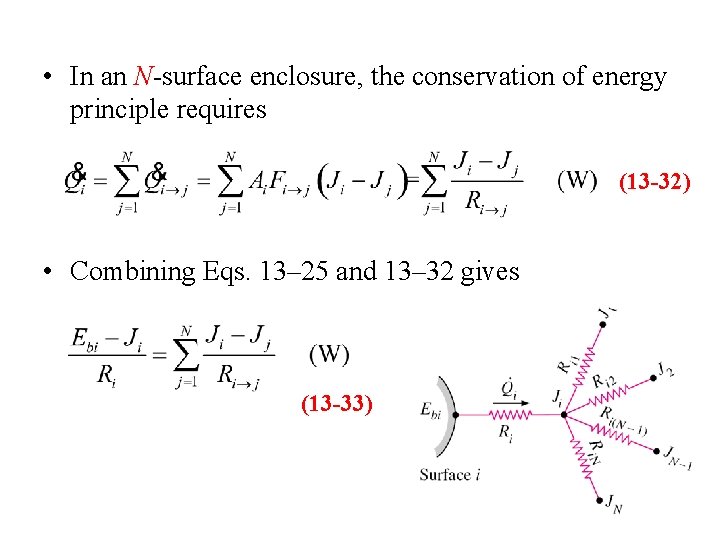
• In an N-surface enclosure, the conservation of energy principle requires (13 -32) • Combining Eqs. 13– 25 and 13– 32 gives (13 -33)
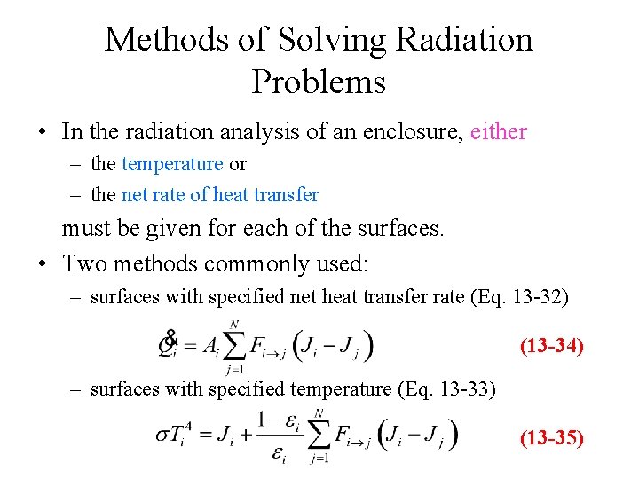
Methods of Solving Radiation Problems • In the radiation analysis of an enclosure, either – the temperature or – the net rate of heat transfer must be given for each of the surfaces. • Two methods commonly used: – surfaces with specified net heat transfer rate (Eq. 13 -32) (13 -34) – surfaces with specified temperature (Eq. 13 -33) (13 -35)
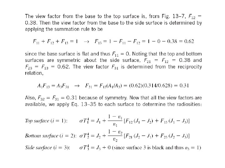
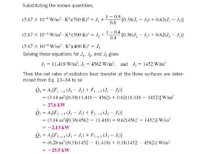
• The equations above give N linear algebraic equations for the determination of the N unknown radiosities for an N-surface enclosure. • Once the radiosities J 1, J 2, . . . , JN are available, the unknown heat transfer rates can be determined from Eq. 13– 34. • The unknown surface temperatures can be determined from Eq. 13– 35. • Two methods to solve the system of N equations: – direct method • very suitable for use with today’s popular equation solvers – network method • not practical for enclosures with more than three or four surfaces • simple and emphasis on the physics of the problem.
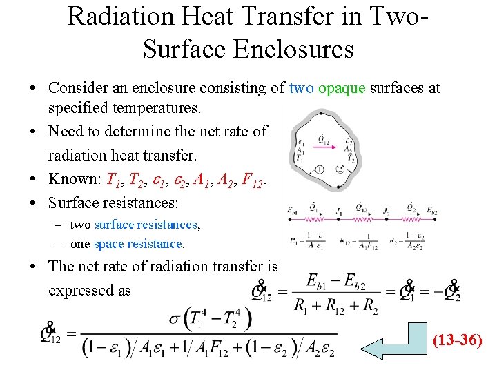
Radiation Heat Transfer in Two. Surface Enclosures • Consider an enclosure consisting of two opaque surfaces at specified temperatures. • Need to determine the net rate of radiation heat transfer. • Known: T 1, T 2, e 1, e 2, A 1, A 2, F 12. • Surface resistances: – two surface resistances, – one space resistance. • The net rate of radiation transfer is expressed as (13 -36)
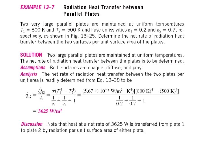
Simplified forms of Eq. 13– 36 for some familiar arrangements
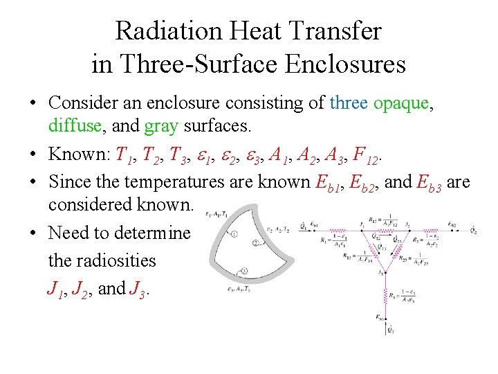
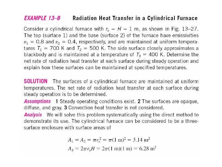
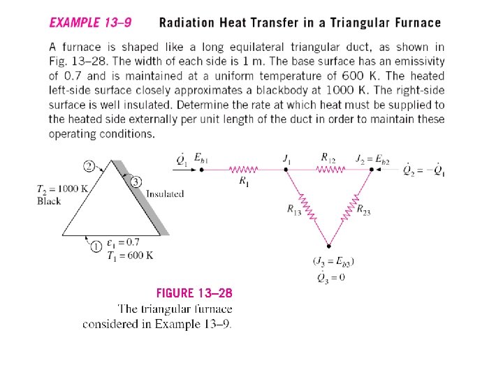
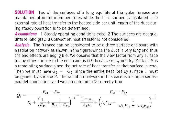
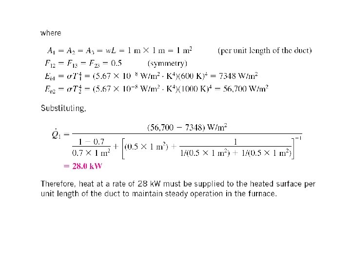
Radiation Heat Transfer in Three-Surface Enclosures • Consider an enclosure consisting of three opaque, diffuse, and gray surfaces. • Known: T 1, T 2, T 3, e 1, e 2, e 3, A 1, A 2, A 3, F 12. • Since the temperatures are known Eb 1, Eb 2, and Eb 3 are considered known. • Need to determine the radiosities J 1, J 2, and J 3.
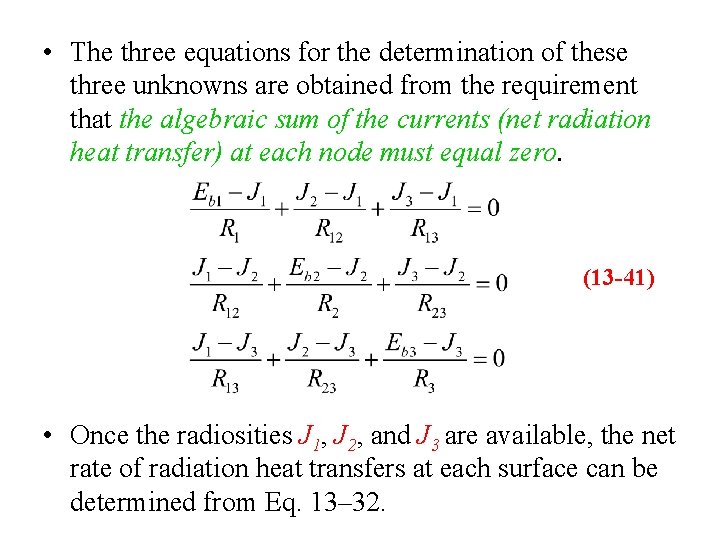
• The three equations for the determination of these three unknowns are obtained from the requirement that the algebraic sum of the currents (net radiation heat transfer) at each node must equal zero. (13 -41) • Once the radiosities J 1, J 2, and J 3 are available, the net rate of radiation heat transfers at each surface can be determined from Eq. 13– 32.
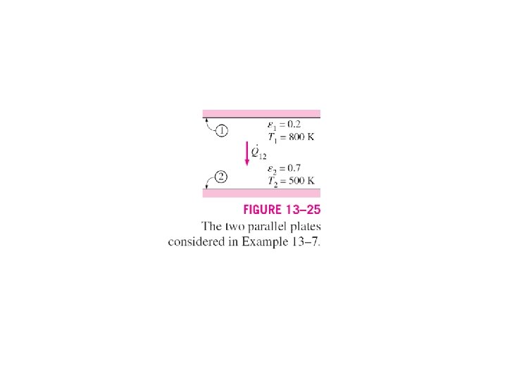
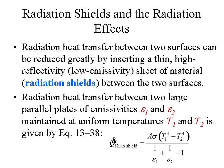
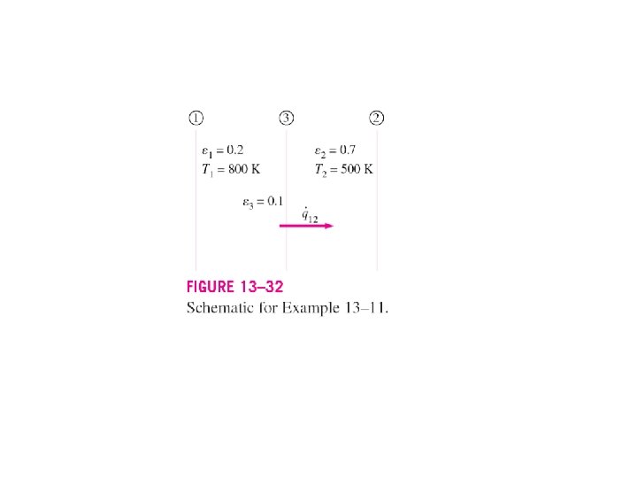
Radiation Shields and the Radiation Effects • Radiation heat transfer between two surfaces can be reduced greatly by inserting a thin, highreflectivity (low-emissivity) sheet of material (radiation shields) between the two surfaces. • Radiation heat transfer between two large parallel plates of emissivities e 1 and e 2 maintained at uniform temperatures T 1 and T 2 is given by Eq. 13– 38:
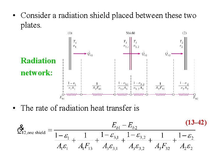
• Consider a radiation shield placed between these two plates. Radiation network: • The rate of radiation heat transfer is (13 -42)
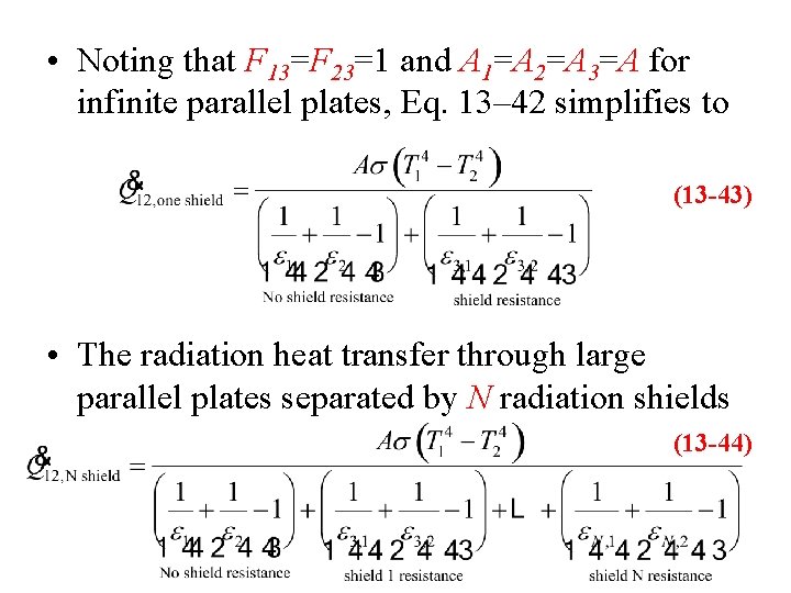
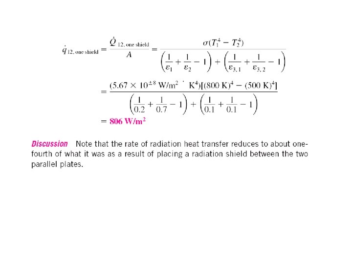
• Noting that F 13=F 23=1 and A 1=A 2=A 3=A for infinite parallel plates, Eq. 13– 42 simplifies to (13 -43) • The radiation heat transfer through large parallel plates separated by N radiation shields (13 -44)
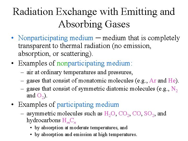
Radiation Exchange with Emitting and Absorbing Gases • Nonparticipating medium ─ medium that is completely transparent to thermal radiation (no emission, absorption, or scattering). • Examples of nonparticipating medium: – air at ordinary temperatures and pressures, – gases that consist of monatomic molecules (e. g. , Ar and He). – gases that consist of symmetric diatomic molecules (e. g. , N 2 and O 2). • Examples of participating medium – asymmetric molecules such as H 2 O, CO 2, CO, SO 2, and hydrocarbons Hm. Cn • by absorption at moderate temperatures, and • by absorption and emission at high temperatures.
The presence of a participating medium complicates the radiation analysis considerably: • A participating medium is a volumetric phenomena, • Gases emit and absorb radiation at a number of narrow wavelength bands, and the gray assumption may not always be appropriate, • The emission and absorption characteristics of the constituents of a gas mixture also depends on the temperature, pressure, and composition of the gas mixture, • Scattering ─ the change of direction of radiation due to reflection, refraction, and diffraction. • We limit our consideration to gases that emit and absorb radiation.
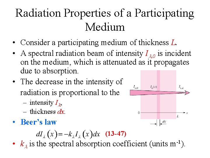
Radiation Properties of a Participating Medium • Consider a participating medium of thickness L. • A spectral radiation beam of intensity Il, 0 is incident on the medium, which is attenuated as it propagates due to absorption. • The decrease in the intensity of radiation is proportional to the – intensity Il, – thickness dx. • Beer’s law (13 -47) • kl is the spectral absorption coefficient (units m-1).
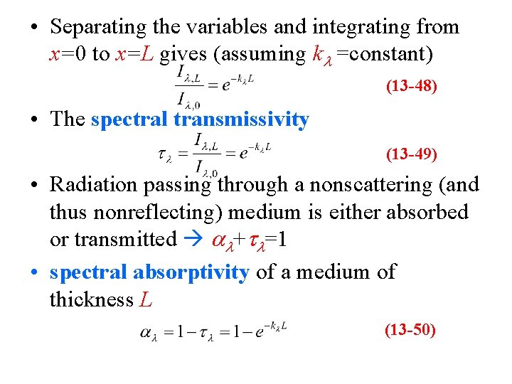
• Separating the variables and integrating from x=0 to x=L gives (assuming kl =constant) (13 -48) • The spectral transmissivity (13 -49) • Radiation passing through a nonscattering (and thus nonreflecting) medium is either absorbed or transmitted al+tl=1 • spectral absorptivity of a medium of thickness L (13 -50)
• From Kirchoff’s law, the spectral emissivity of the medium is (13 -51) • The spectral absorption coefficient of a medium (and thus el, al, tl), in general, vary with: – wavelength, – temperature, – pressure, and – composition. • Optically thick medium ─ a medium with a large value of kl L. • For optically thick medium el≈al≈1.
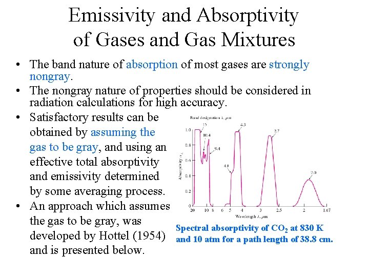
Emissivity and Absorptivity of Gases and Gas Mixtures • The band nature of absorption of most gases are strongly nongray. • The nongray nature of properties should be considered in radiation calculations for high accuracy. • Satisfactory results can be obtained by assuming the gas to be gray, and using an effective total absorptivity and emissivity determined by some averaging process. • An approach which assumes the gas to be gray, was Spectral absorptivity of CO 2 at 830 K developed by Hottel (1954) and 10 atm for a path length of 38. 8 cm. and is presented below.
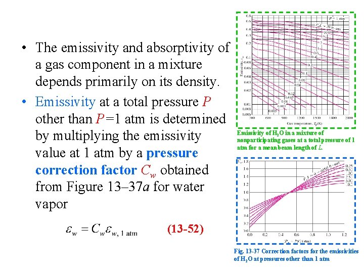
• The emissivity and absorptivity of a gas component in a mixture depends primarily on its density. • Emissivity at a total pressure P other than P=1 atm is determined by multiplying the emissivity value at 1 atm by a pressure correction factor Cw obtained from Figure 13– 37 a for water vapor Emissivity of H 2 O in a mixture of nonparticipating gases at a total pressure of 1 atm for a mean beam length of L. (13 -52) Fig. 13 -37 Correction factors for the emissivities of H 2 O at pressures other than 1 atm
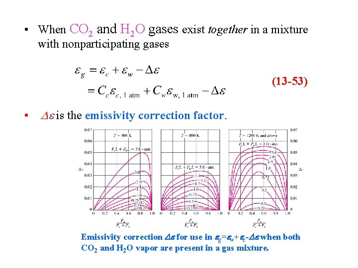
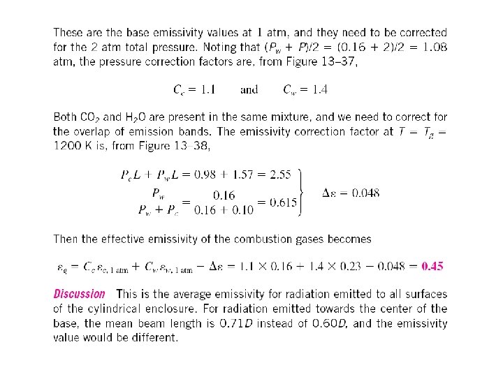
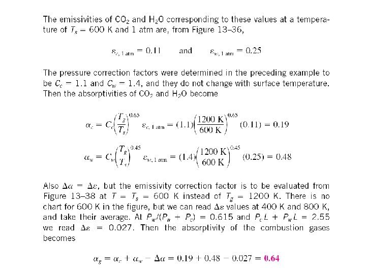
• When CO 2 and H 2 O gases exist together in a mixture with nonparticipating gases (13 -53) • De is the emissivity correction factor. Emissivity correction De for use in eg=ew+ec-De when both CO 2 and H 2 O vapor are present in a gas mixture.
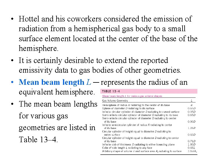
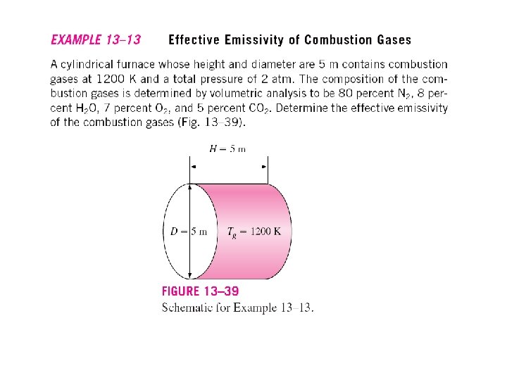
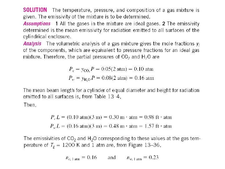
• Hottel and his coworkers considered the emission of radiation from a hemispherical gas body to a small surface element located at the center of the base of the hemisphere. • It is certainly desirable to extend the reported emissivity data to gas bodies of other geometries. • Mean beam length L ─ represents the radius of an equivalent hemisphere. • The mean beam lengths for various gas geometries are listed in Table 13– 4.
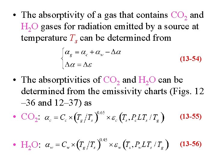
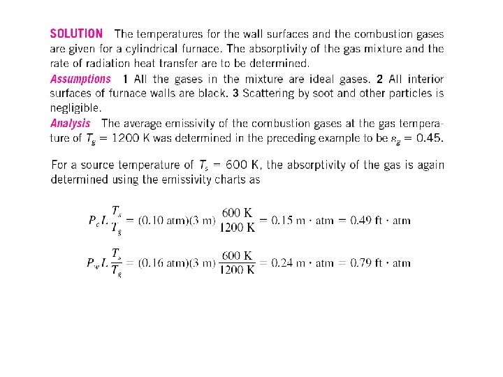
• The absorptivity of a gas that contains CO 2 and H 2 O gases for radiation emitted by a source at temperature Ts can be determined from (13 -54) • The absorptivities of CO 2 and H 2 O can be determined from the emissivity charts (Figs. 12 – 36 and 12– 37) as (13 -55) • CO 2: • H 2 O: (13 -56)
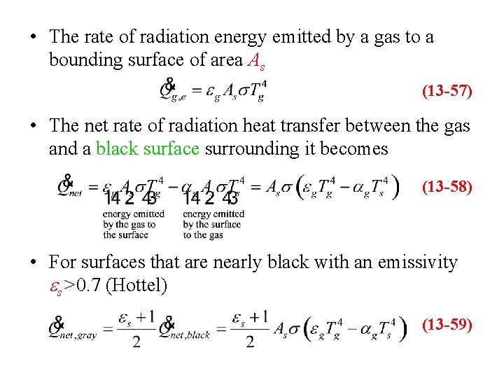
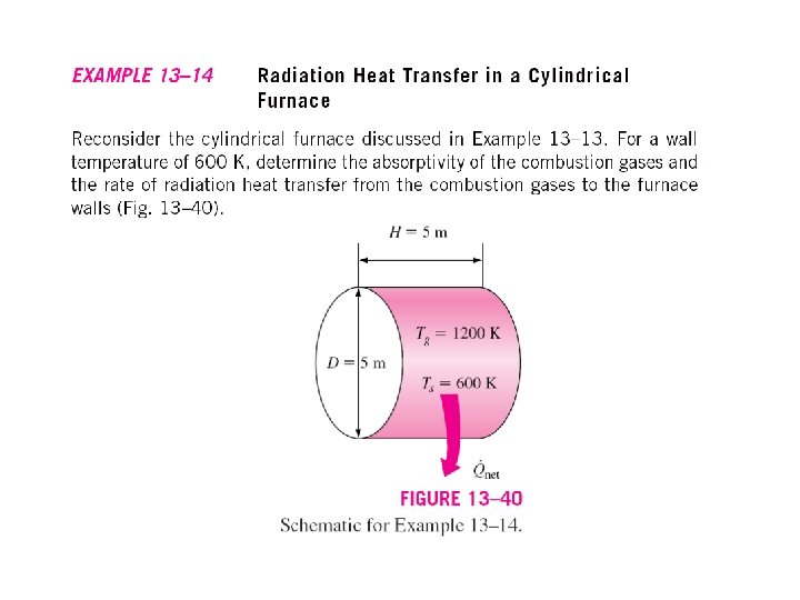
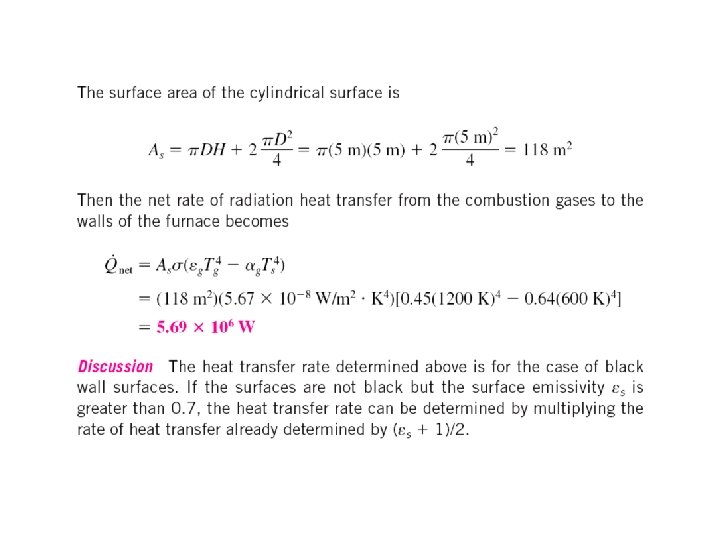
• The rate of radiation energy emitted by a gas to a bounding surface of area As (13 -57) • The net rate of radiation heat transfer between the gas and a black surface surrounding it becomes (13 -58) • For surfaces that are nearly black with an emissivity es>0. 7 (Hottel) (13 -59)