Chapter 13 POTENTIOMETRIC ELECTRODES AND POTENTIOMETRY POTENTIOMETRIC ELECTRODES


right − (half-reaction)left (to give a positive Ecell and the")


 q The term “saturated” refers to the concentration of potassium")


 electrode")


 It is apparent that the glass electrode will undergo a 2. 303")


 Ecell = Eleft− Eright b) Ecell =Eref −")
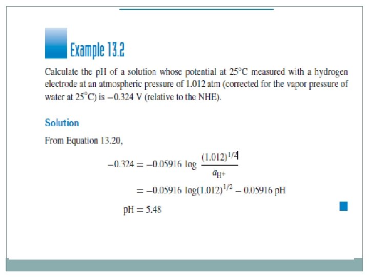
 p. H= 2. 41 b) p. H=5. 48 c) p. H=10. 1")

,")
- Slides: 103
Chapter 13 POTENTIOMETRIC ELECTRODES AND POTENTIOMETRY
POTENTIOMETRIC ELECTRODES AND POTENTIOMETRY Ch. 13 In this chapter Understand the concept of the various types of electrodes that can be used for measuring solution potentials. How to select the proper one for measuring a given analyte. The apparatus for making potentiometric measurements is described along with limitations and accuracies of potentiometric measurements. The important glass p. H electrode is described, as well as standard buffers required for its calibration. The various kinds of ion-selective electrodes are discussed.
Type of electrodes: 13. 1 Metal Electrodes for Measuring the Metal Cation 1 - An electrode of this type is a metal in contact with a solution containing the cation of the same metal. example : a silver metal electrode dipping in a solution of silver nitrate. For all electrode systems, an electrode half-reaction can be written: Mn+ + ne− = M Ag+ + e− = Ag The electrode system can be represented by M/Mn+, in which the line represents an electrode–solution interface. For the silver Electrode: Ag|Ag+
The potential of the electrode is described by the Nernst equation: An electrode of this type is a metal in contact with a solution containing the cation of the same metal. (13. 3) where a. Ag+ represents the activity of the silver ion The potential calculated from. Equation 13. 3 is the potential relative to the normal hydrogen electrode (NHE).
The potential becomes increasingly positive with increasing Ag+ (the case for any electrode measuring a cation). That is, in a cell measurement using the NHE as the second half-cell, . the voltage is Emeasd. = Ecell = Eind vs. NHE = Eind − ENHE The indicator electrode is the one where Eind is the potential of the indicator electrode (the one that responds to the test that responds to the analyte. solution, Ag+ ions in this case). ENHE is zero, Ecell = Eind corresponds to writing the cells as: Eref | solution |Eind
and Ecell = Eright − Eleft = Eind − Eref = Eind – constant Where Eref is the potential of the reference electrode, whose potential is constant. Ecell (or Eind) may be positive or negative, depending on the activity of the silver ion or the relative potentials of the two electrodes. In potentiometric measurements, measure the potential at zero current, at the indicating electrode surface. The potential of the test electrode (indicating electrode) changes with analyte concentration, as measured against some constant reference electrode. The activity of silver metal above, as with other pure substances, is taken as unity.
So an electrode of this kind can be used to monitor the activity of a metal ion in solution. There are few reliable electrodes of this type because many metals tend to form an oxide coating that changes the potential. Any pure substance does not numerically appear in the Nernst equation (e. g. , Cu, H 2 O); their activities are taken as unity.
13. 2 Metal–Metal Salt Electrodes for Measuring the Salt Anion 1 - The general form of this type of electrode is M|MX|Xn−, where MX is a slightly soluble salt. An example is the silver–silver chloride electrode: Ag|Ag. Cl(s)|Cl− The (s) indicates a solid, (g) is used to indicate a gas, and (l) is used to indicate a pure liquid. A vertical line denotes a phase boundary between two different solids or a solid and a solution. The half-reaction is Ag. Cl(s) + e− = Ag(s) + Cl−
Where n = 1 1 -This electrode, then, can be used to measure the activity of chloride ion in solution. 2 -The activity of chloride increases, the potential decreases. This is true of any electrode measuring an anion—the opposite for a cation electrode. 3 -A silver wire is coated with silver chloride precipitate. 4 -A silver wire is dipped in a chloride solution, a thin layer of silver chloride. 5 -This electrode can be used to monitor either a. Cl− or a. Ag+. It really senses only silver ion, and the activity of this is determined by the solubility of the slightly soluble Ag. Cl. Since a. Cl− = Ksp/a. Ag+,
The Equation can be rewritten: Since a. Cl− = Ksp/a. Ag+,
13. 3 Redox Electrodes—Inert Metals 1 -An inert metal is in contact with a solution containing the soluble oxidized and reduced forms of the redox half-reaction. 2 -The inert metal used is usually platinum. 3 - The potential of such an inert electrode is determined by the ratio at the electrode surface of the reduced and oxidized species in the halfreaction: Ma+ + ne− = M(a-n)+
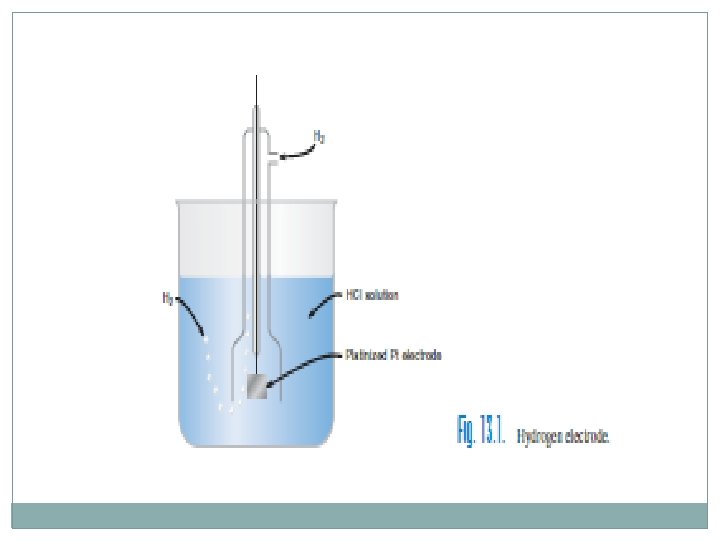
The p. H is usually held constant, and so the ratio a. Mn 2+/a. Mn. O 4− is measured, as in a redox titration. A very important example of this type of electrode is the hydrogen electrode, Pt|H 2, H+: H+ + e− =1/2 H 2
1 - The construction of the hydrogen electrode is shown in Figure 13. 1. 2 - The platinum black provides a larger surface area for adsorption of hydrogen molecules and catalyzes their oxidation. 3 - platinum black can adsorb traces of other substances such as organic molecules or H 2 S, causing erratic behavior of the electrode. 4 - The pressure of gases, in atmospheres, is used in place of activities. 5 - If the hydrogen pressure is held at 1 atm, then, since E 0 for Equation 13. 19 is defined as zero,
While the hydrogen electrode is very important for specific applications (e. g. , establishing standard potentials or the p. H of standard buffers), its use for routine p. H measurements is limited: 1 - It is inconvenient to prepare and use. 2 - The partial pressure of hydrogen must be established at the measurement temperature. 3 - The solution should not contain other oxidizing or reducing agents since these will alter the potential of the electrode
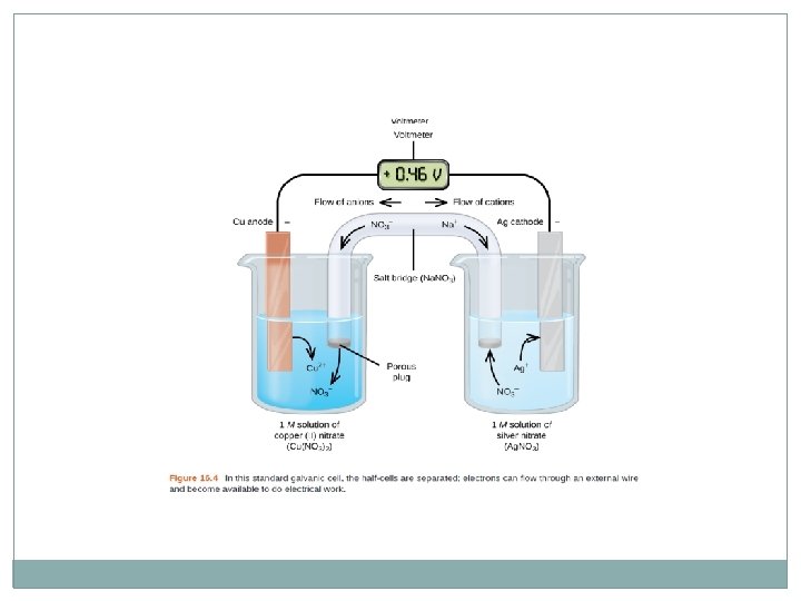
13. 4 Voltaic Cells without Liquid Junction—For Maximum Accuracy 1 -To make potential measurements, a complete cell consisting of two half-cells must be set up. 2 - One half-cell usually is comprised of the test solution and an electrode whose potential is determined by the analyte, This electrode is the indicator electrode. 3 - The other half-cell whose potential is not dependent on the analyte. This half-cell electrode is the reference electrode. Its potential is constant. 4 -The measured cell voltage reflects the indicator electrode potential relative to that of the reference electrode. Since the reference electrode potential is constant, any changes in potential of the indicator electrode will be reflected by an equal change in the cell voltage.
There are two basic ways a cell: without or with a salt bridge The first is called a cell without liquid junction. Example of a cell of this type: Pt|H 2(g), HCl(solution)|Ag. Cl(s)|Ag The solid line represents an electrode–solution interface, voltaic cell, spontaneous cell reaction, (positive Ecell). The hydrogen electrode is the anode, since its potential is the more negative.
The potential of the left electrode would be given by Equation H+ + e− =1/2 H 2 the right electrode would be given by Equation : Ag. Cl(s) + e− = Ag(s) + Cl−
The cell voltage would be equal to the difference in these two potentials:
The cell reaction = (half-reaction)right − (half-reaction)left (to give a positive Ecell and the spontaneous reaction), or Ag. Cl + e− = Ag + Cl− H+ + e− =1/2 H 2 __________ Ag. Cl + 1/2 H 2 = Ag + Cl− + H+ The voltage would decrease with increasing chloride ion. If we were to use the hydrogen electrode as the indicating electrode to measure hydrogen ion activity or p. H, we would reverse the cell and the voltage (and indicator electrode potential) would increase with increasing acidity or decreasing p. H Cells without liquid junction are always used for the most accurate measurements.
13. 5 Voltaic Cells with Liquid Junction An example of this type of cell is: Hg|Hg 2 Cl 2(s)|KCl(saturated)||HCl(solution), H 2(g)|Pt 1 - The double line represents the liquid junction between two dissimilar solutions and is usually in the form of a salt bridge. 2 -The purpose of this is to prevent mixing of the two solutions. In this way, the potential of one of the electrodes will be constant. 3 -The electrode on the left of cell is the saturated calomel electrode, which is a commonly used reference electrode. 4 -The cell is set up using the hydrogen electrode as the indicating electrode to measure p. H.
LIQUID-JUNCTION POTENTIAL——WE CAN’T IGNORE THIS The presence of a liquid-junction potential limits the accuracy of potentiometric measurements. There is a potential associated with the liquid junction, called the liquid-junction potential. Ecell = (Eright − Eleft) + Ej where Ej is the liquid-junction potential; Ej may be positive or negative. The liquid junction potential results from the unequal diffusion of the ions on each side of the boundary. A careful choice of salt bridge can minimize the liquidjunction.
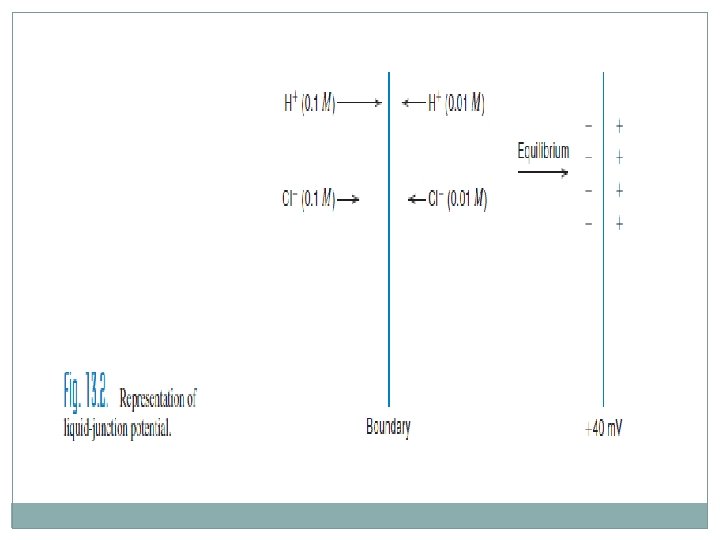
1 - A typical boundary might be a fine-porosity sintered -glass frit with two different solutions on either side of it. 2 - The frit prevents appreciable mixing of the two solutions. 3 - The simplest type of liquid junction occurs between two solutions containing the same electrolyte at different concentrations. An example is HCl (0. 1 M)||HCl (0. 01 M), illustrated in Figure 13. 2.
4 - Both hydrogen ions and chloride ions will migrate across the boundary in both directions, but the net migration will be from the more concentrated to the less concentrated side of the boundary, the driving force for this migration being proportional to the concentration difference. 5 - Hydrogen ions migrate about five times faster than chloride ions. 6 -A net positive charge is built up on the right side of the boundary, leaving a net negative charge on the left side; that is, there is a separation of charge, and this represents a potential.
7 - A steady state is rapidly achieved by the action of this buildup positive charge in inhibiting the further migration of hydrogen ions; the converse applies to the negative charge on the left-hand side. 8 - A constant potential difference is quickly attained between the two solutions. 9 - The Ej for this junction is +40 m. V, and Ecell = (Eright − Eleft) + 40 m. V. This Ej is very large, owing to the rapid mobility of the hydrogen ion. As the concentration of HCl on the left side of the boundary is decreased, the net charge built up will be less, and the liquid-junction potential will be decreased until, at equal concentration, it will be zero, because equal amounts of HCl diffuse in each direction.
A second example of this type of liquid junction is 0. 1 M KCl/0. 01 M KCl. This situation is completely analogous to that above, except that in this case the K+ and Cl− ions migrate at nearly the same rate, with the chloride ion moving only about 4% faster. So a net negative charge is built up on the right side of the junction, but it will be relatively small. Thus, Ej will be negative and is equal to − 1. 0. We minimize the liquid-junction potential by using a high concentration of a salt whose ions have nearly equal mobility, for example, KCl.
HOW DO WE MINIMIZE THE LIQUID-JUNCTION POTENTIAL? 1 -The nearly equal migration of potassium and chloride ions makes it possible to significantly decrease the liquid-junction potential. 2 -Very rarely can the liquid-junction potential be considered to be negligible 3 -A potassium chloride salt bridge, at or near saturation, is usually employed, except when these ions may interfere in a determination. Ammonium chloride or potassium nitrate may be used if the potassium or chloride ion interferes. 4 -Various types of electrolyte junctions or salt bridges, such as a groundglass joint, a porous glass or ceramic plug, or a fine capillary tip.
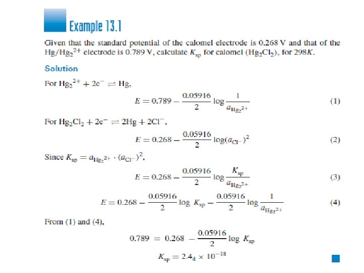
13. 6 Reference Electrodes: The Saturated Calomel Electrode 1 - Arequirement of a reference electrode is that its potential be fixed and stable, unaffected by the passage of small amounts of current required in making potentiometric measurements. 2 -Reference electrode are usually metal–metal salt. The two most common are the Hg/Hg 2 Cl 2 (calomel) and the Ag/Ag. Cl 3 -A commonly used reference electrode is the saturated calomel electrode (SCE):
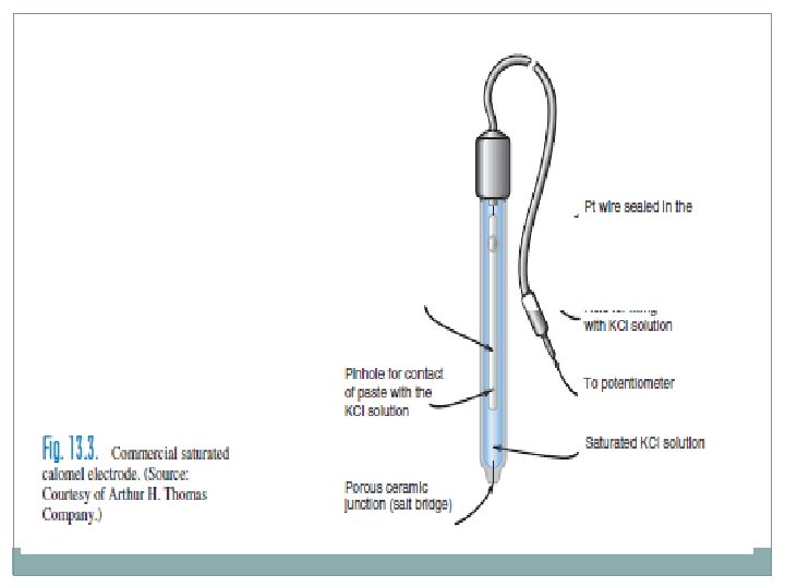
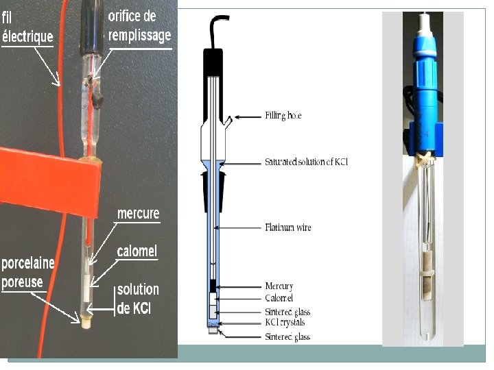
saturated calomel electrode (SCE) q The term “saturated” refers to the concentration of potassium chloride; and at 25◦C, q The potential of the SCE is 0. 242 V versus NHE. q An SCE consists of a small amount of mercury mixed with some solid Hg 2 Cl 2 (calomel), solid KCl, and enough saturated KCl solution to moisten the mixture. q This is contacted with a saturated KCl solution containing some solid KCl to maintain saturation. q A platinum electrode is immersed in the paste to make contact with the small mercury pool formed, and the connecting wire from that goes to one terminal of the potential measuring device.
q. A salt bridge serves as the contact between the KCl solution and the test solution and is usually a fiber or porous glass frit wetted with the saturated KCl solution. q. A commercial probe-type SCE is shown in Figure 13. 3. This contains a porou fiber or frit as the salt bridge in the tip that allows very slow leakage of the saturated potassium chloride solution. It has a small mercury pool area and so the current it can pass without its potential being affected is limited.
13. 7 Measurement of Potential We create a voltaic cell with the indicator and reference electrodes. We measure the voltage of the cell, giving a reading of the indicator electrode potential relative to the reference electrode. We can relate this to the analyte activity or concentration using the Nernst equation.
THE p. H METER 1 -p. H measurements with a glass (or other) electrode involve the measurement of potentials. 2 -The p. H meter is a voltmeter that converts the unknown voltage to current and read out. 3 -The p. H meter is a voltage measuring device designed for use with high-resistance glass electrodes and can be used to measure potential in both low- and highresistance circuits. 4 -A p. H meter is a high-input impedance voltmeter that senses the cell voltage, provides a digital readout (either in terms of voltage or p. H).
5 -Because very little current is drawn, chemical equilibrium is not perceptibly disturbed. 6 -and it is best suited for irreversible reactions. 7 -The resistance of a typical glass p. H electrode is of the order of 108 ohm. 8 -Sufficiently sensitive p. H meters are available that will measure the potential with a resolution of 0. 1 m. V. These are well suited for direct potentiometric measurements with both p. H electrodes and other ion -selective electrodes.
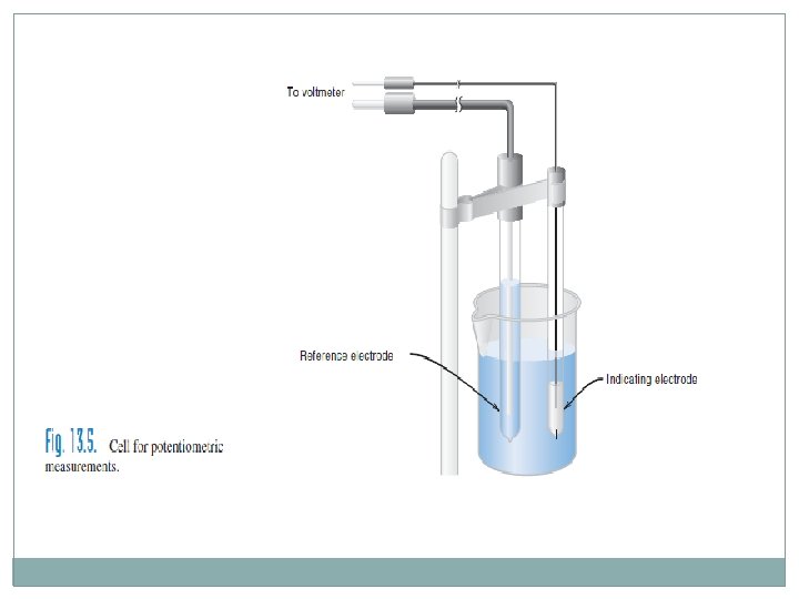
THE CELL FOR POTENTIAL MEASUREMENTS In potentiometric measurements, a cell of the type shown in Figure 13. 5 is set up. For direct potentiometric measurements in which the activity of one ion is to be calculated from the potential of the indicating electrode, the potential of the reference electrode will have to be known or determined. The voltage of the cell is described by Equation 13. 7, (Ecell = Eright − Eleft = Eind − Eref = Eind – constant) and when a salt bridge is employed, the liquid-junction potential must be included. Then, Ecell = (Eind − Eref) + Ej ( 13. 30)
The Ej can be combined with the other constants in Equation 13. 30 into a single constant, assuming that the liquid-junction potential does not differ significantly from one solution to the next. We are forced to accept this assumption since Ej cannot be evaluated under most circumstances. Eref , Ej, and E 0 ind are a constant k: k = E 0 ind − Eref + Ej The constant k is determined by measuring the potential of a standard solution in which the activities are known.
13. 8 Determination of Concentrations from Potential Measurements § we are interested in determining the concentration of a test substance rather than its activity. § If the ionic strength is maintained constant, activity coefficients are constant and can be included in k (to be called a new constant, k'). So concentrations can be determined from measured cell potentials. So, We can then write for the log term in the Nernst equation:
It is best to construct a calibration curve of potential versus log concentration; �The slope is ± 2. 303 RT/n. F or ± 0. 059/n, �The intercept of the plot is the constant, k', which includes the standard potential, reference electrode potential, liquid junction potential, and the activity coefficient.
13. 9 Residual Liquid-Junction Potential We have assumed above in Equations 13. 32 and 13. 34 that k or k' is the same in measurements of both standards and samples. This is so only if the liquid-junction potential at the reference electrode is the same in both solutions. But the test solution will usually have a somewhat different composition from the standard solution, and the magnitude of the liquid-junction potential will vary. The difference in the two liquid-junction potentials is called the residual liquid-junction potential, and it will remain unknown. The difference can be kept to a minimum by keeping the ionic strength of both solutions as close as possible, and especially by keeping the p. H of the test solution and the p. H of the standard solution as close as possible.
13. 11 Glass p. H Electrode 1 -The glass electrode, because of its convenience, is used almost universally for p. H measurements today. 2 -Its potential is essentially not affected by the presence of oxidizing or reducing agents, and it is operative over a wide p. H range. 3 -It is fast responding. No other p. H-measuring electrode possesses all these properties.
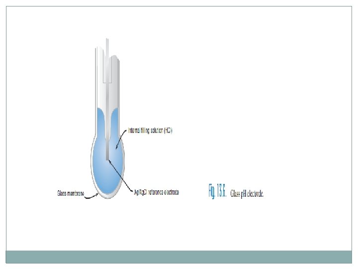
PRINCIPLE OF THE GLASS ELECTRODE A typical construction of a p. H glass electrode is shown in Figure 13. 6. 1 - For measurement, only the bulb need be submerged. 2 -There is an internal reference electrode and electrolyte (Ag|Ag. Cl|Cl−) for making electrical contact with the glass membrane; its potential is necessarily constant and is set by the concentration of HCl. A complete cell, then, can be represented by
1 -The double line represents the salt bridge of the reference electrode. 2 -The glass electrode is attached to the indicating electrode terminal of the p. H meter while the external reference electrode (e. g. , SCE) is attached to the reference terminal. 3 -potential of the glass membrane is given by
13. 38 where k is a constant that includes the potentials of the two reference electrodes, the liquid-junction potential, a potential at the glass membrane due to H+ (internal), and a term known as the asymmetry potential.
The asymmetry potential is a small potential across the membrane that is present even when the solutions on both sides of the membrane are identical. It is associated with factors such as nonuniform composition of the membrane, strains within the membrane, mechanical and chemical attack of the external surface, and the degree of hydration of the membrane. It slowly changes with time, especially if the membrane is allowed to dry out, and is unknown. For this reason, a glass p. H electrode must be calibrated at least once a day. The asymmetry potential will vary from one electrode to another, owing to differences in construction of the membrane. Since p. H = −log a. H+, Equation 13. 38 can be rewritten 1
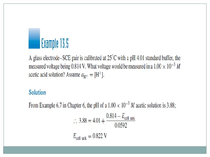
(13. 39) It is apparent that the glass electrode will undergo a 2. 303 RT/F-volt response for each change of 1 p. H unit (10 -fold change in a. H+); k must be determined by calibration with a standard buffer of known p. H: (13. 41)
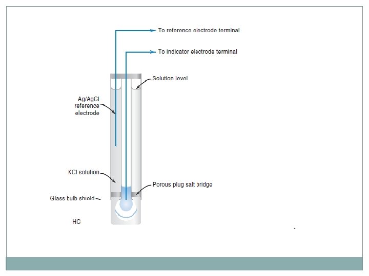
COMBINATION p. H ELECTRODES 1 - Both an indicating and a reference electrode (with salt bridge) are required to make a complete cell so that potentiometric measurements can be made. 2 - It is convenient to combine the two electrodes into a single probe, so that only small volumes are needed for measurements. 3 - A typical construction of a combination p. H–reference electrode is shown in Figure 13. 7. 4 -It consists of a tube within a tube, the inner one housing the p. H indicator electrode and the outer one housing the reference electrode (e. g. , a Ag/Ag. Cl electrode) and its salt bridge. There is one lead from the combination electrode, but it is split into two connectors at the end, one (the larger) going to the p. H electrode terminal and the other going to the reference electrode terminal. It is important that the salt bridge be immersed in the test solution in order to complete the cell. The salt bridge is often a small plug in the outer ring rather than a complete ring as illustrated here. Combination electrodes are convenient, and therefore the most commonly used.
WHAT DETERMINES THE GLASS MEMBRANE POTENTIAL? 1 - The p. H glass electrode functions as a result of ion exchange on the surface of a hydrated layer. 2 - The membrane of a p. H glass electrode consists of chemically bonded Na 2 O and −Si. O 2. The surface of a new glass electrode contains fixed silicate groups associated with sodium ions, −Si. O−Na+. 3 - For the electrode to work properly, it must first be soaked in water. During this process, the outer surface of the membrane becomes hydrated. 5 - The inner surface is already hydrated. 6 - glass membrane is usually 30 to 100 μm thick, and the hydrated layers are 10 to 100 nm thick.
WHAT DETERMINES THE GLASS MEMBRANE POTENTIAL? 7 - When the outer layer becomes hydrated, the sodium ions are exchanged for protons in the solution: −Si. O−Na+ + H+ ===== −Si. O−H+ + Na+ (13. 43) solid solution 8 - Other ions in the solution can exchange for the Na+ (or H+) ions, but the equilibrium constant for the above exchange is very large because of the affinity of the glass for protons. Thus, the surface of the glass is made up almost entirely of silicic acid, except in very alkaline solution, where the proton concentration is small. The −Si. O− sites are fixed, but the protons are free to move and exchange with other ions.
The potential of the membrane 1 - The potential of the membrane consists of two components of: The boundary potential and the diffusion potential. 2 - The former is almost the sole hydrogen ion activity determining potential. 3 - The boundary potential resides at the surface of the glass membrane, that is, at the interface between the hydrated gel layer and the external solution. When the electrode is dipped in an aqueous solution, a boundary potential is built up, which is determined by the activity of hydrogen ions in the external solution and the activity of hydrogen ions on the surface of the gel. One explanation of the potential is that the ions will tend to migrate in the direction of lesser activity, much as at a liquid junction. The result is a microscopic layer of charge built up on the surface of the membrane, which represents a potential. 4 - Hence, as the solution becomes more acidic (the p. H decreases), protons migrate to the surface of the gel, building up a positive charge, and the potential of the electrode increases, as indicated by Equations 13. 37 and 13. 38. The reverse is true as the solution becomes more alkaline.
The potential of the membrane 5 - The diffusion potential results from a tendency of the protons in the inner part of the gel layer to diffuse toward the dry membrane, which contains −Si. O−Na+, and a tendency of the sodium ions in the dry membrane to diffuse to the hydrated layer. 6 - The ions migrate at a different rate, creating a type of liquidjunction potential. But a similar phenomenon occurs on the other side of the membrane, only in the opposite direction. 7 - These in effect cancel each other, and so the net diffusion potential is very small, and the potential of the membrane is determined largely by the boundary potential. (Small differences in diffusion potentials may occur due to differences in the glass across the membrane—these represent a part of the asymmetry potential. )
The type of the error 1 - Two types of error occur that result in non-Nernstian behavior 2 - The first is called the alkaline error. Such error is due to the capability of the membrane for responding to other cations besides the hydrogen ion. As the hydrogen ion activity becomes very small. 3 - Sodium ions will exchange with the protons in the layer when the hydrogen ion activity in the external solution is very low (reverse of Equation 13. 43).
The alkaline error 4 - The error is negligible at p. H less than about 9; but at p. H values above this, the H+ concentration is very small relative to that of other ions. 5 - The electrode response to the other ions such as Na+, K+ and the p. H reading is too low. 6 - The magnitude of this negative error is illustrated in Figure 13. 8. Sodium ion causes the largest errors. 7 -Commercial general-purpose glass electrodes are usually supplied with a graphically represented alkaline error correction values, and if the sodium ion concentration is known, these electrodes are useful up to p. H about 11.
Tthe alkaline error 8 - By a change in the composition of the glass, the affinity of the glass for sodium ion can be reduced. 9 - If the Na 2 O in the glass membrane is largely replaced by Li 2 O, then the error due to sodium ions is markedly decreased. This is the so-called lithium glass electrode, high-p. H electrode, or full-range electrode (0 to 14 p. H range). 10 -Most p. H electrodes in use today have glass membranes formulated to be capable of measurement up to p. H 13. 5 with reasonable accuracy if sodium error is corrected for.
The Acid error ACID ERROR 1 - At very low p. H values (p. H<1), the gel layer of the p. H-sensitive glass membrane absorbs acid molecules. This absorption decreases the activity of hydrogen ions and results in a lower potential at the outer membrane phase boundary. 2 - The p. H measurement therefore shows a higher p. H value than the actual p. H value of the sample solution. 3 - A second and possibly greater contributor to the acid error is more aptly described as the water activity error, is the second type causing non-Nernstian response. Such error occurs because the potential of the membrane depends on the activity of the water with which it is in contact. If the activity is unity, the response is Nernstian.
4 - In very acidic solutions, the activity of water is less than unity and a positive error in the p. H reading results. 5 - A similar type of error will result if the activity of the water is decreased by a high concentration of dissolved salt or by addition of nonaqueous solvent such as ethanol. In these cases, a large liquid-junction potential may also be introduced another error will thereby result, although this is not very large with small amounts of ethanol. 6 - Similiar to specially formulated electrodes for use at strongly alkaline p. H, specialized electrodes are available for use in strongly acid solutions that exhibit considerably less acid error. Acid error, in general, is smaller than alkaline error.
13. 12 Standard Buffers—Reference for p. H Measurements 1 - The National Institute of Standards and Technology (NIST) developed a series of certified standard buffers for use in calibrating p. H measurements. 2 - The p. H values of the buffers were determined by measuring their p. H using a hydrogen-indicating electrode in a cell without liquid Junction (similar to the cell given by Equation 13. 22). 3 - A silver/silver chloride reference electrode was used.
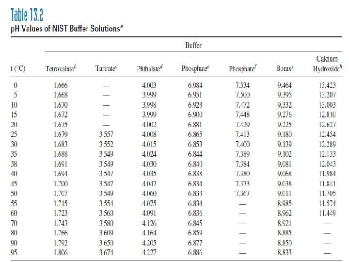
13. 12 Standard Buffers—Reference for p. H Measurements 4 -The compositions and p. H of NIST standard buffers are given in Table 13. 2. 5 -when accurate p. H measurement is necessary, the p. H meter is calibrated with two standard buffers. 6 - The p. H of the buffers is temperature dependent because of the dependence of the ionization constants of the parent acids Kaor bases Kb on temperature. 7 -The KH 2 PO 4 − Na 2 HPO 4 buffer (p. H 7. 384 at 38◦C) is particularly suited for calibration for blood p. H measurements. Many blood p. H measurements are made a 38◦C, which is near body temperature; thus, the p. H of the blood in the body is Indicated.
13. 13 Accuracy of p. H Measurements 1 - The residual liquid-junction potential limits the accuracy of p. H measurement. Always calibrate at a p. H close to that of the test solution. 2 - We have mentioned that this residual liquid-junction potential is minimized by keeping the p. H and compositions of the solutions as near as possible.
13. 14 Using the p. H Meter—How Does It Work? 1 - If voltage is measured directly, Equation 13. 40 or 13. 42 is applied to calculate the p. H. 2 - The value of 2. 303 RT/F at 298. 16 K (25◦C) is 0. 05916; if a different temperature is used, this value should be corrected in direct proportion to the absolute temperature.
3 -A digital p. H meter is shown in Figure 13. 10.
4 - The potential scale is calibrated in p. H units, with each p. H unit equal to 59. 16 m. V at 25◦C (Equation 13. 39). 5 -The p. H meter is adjusted to indicate the p. H of the standard buffer or the calibration function will cause it to calibrate itself with the known p. H of the calibrant buffer. 6 - Then, the standard buffer is replaced by the unknown solution and the p. H is read. 7 - This procedure, in effect, sets the constant k in Equation 13. 40 and adjusts for the asymmetry potential as well as the other constants included in k.
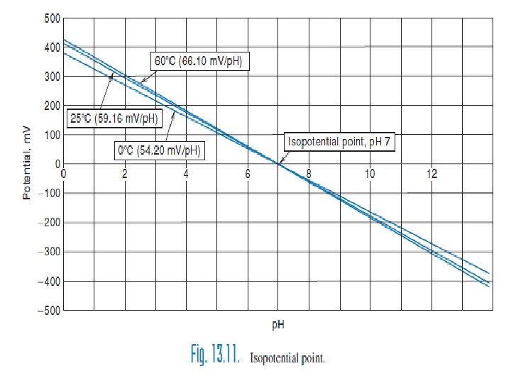
8 - Most p. H meters contain a temperature adjustment dial, which changes the sensitivity response (m. V/p. H) so that it will be equal to 2. 303 RT/F. For example, it is 54. 1 m. V at 0◦C and 66. 0 m. V at 60◦C The temperature setting on the p. H meter adjusts T in the RT/n. F value, which determines the slope of the potential versus p. H buffers. 9 - Electrodes and meters are designed to have a point in calibrations lines, in the midrange of activity measurements, where the potential essentially has no variation with temperature.
10 - For p. H glass electrodes, this is set at p. H 7 (Figure 13. 11). 11 - This is called the isopotential point, and the potential is zero. (p. H meters actually measure potential which is converted to p. H reading, and potentials can be recorded directly. ) 11 - Any potential reading different from 0 m. V for a p. H 7. 0 standard buffer is called the offset of that electrode. 12 - When the temperature is changed, the calibration slope changes, and the intersection of the curves establishes the actual isopotential point.
13. 15 p. H Measurement of Blood—Temperature Is Important 1 -The p. H measurement of blood samples must be made at body temperature to be meaningful. 2 - Blood samples must be kept anaerobically to prevent loss or absorption of CO 2. 3 - To prevent coating of the electrode, flush the sample from the electrode with saline solution after each measurement. A residual blood film can be removed by dipping for only a few minutes in 0. 1 M Na. OH, followed by 0. 1 M HCl and water or saline.
13. 16 p. H Measurements in Nonaqueous Solvents Measurement of p. H in a nonaqueous solvent when the electrode is standardized with an aqueous solution has little significance in terms of possible hydrogen ion activity because of the unknown liquid-junction potential, which can be rather large, depending on the solvent.
13. 17 Ion-Selective Electrodes 1 - Various types of membrane electrodes have been developed in which the membrane potential is selective toward a given ion or ions, just as the potential of the glass membrane of a conventional glass electrode is selective toward hydrogen ions. 2 - These electrodes are important in the measurement of ions, especially in small concentrations. 3 -. None of these electrodes is specific for a given ion, but each will possess a certain selectivity toward a given ion or ions. So they are properly referred to as ion selective electrodes (ISEs)
Type of ISEs There are three type based on the kind of membrene type: 1 - GLASS MEMBRANE ELECTRODES 2 - SOLID-STATE ELECTRODES 3 - LIQUID—LIQUID ELECTRODES
GLASS MEMBRANE ELECTRODES 1 - These are similar in construction to the p. H glass electrode. 2 -Varying the composition of the glass membrane can cause the hydrated glass to acquire an increased affinity for various monovalent cations, with a much lower affinity for protons than the p. H glass electrode has. 3 - The membrane potential becomes dependent on these cations, probably through an ion exchange mechanism similar to that presented for the glass p. H elctrode; that is, a boundary potential is produced, determineed by the relative activities of the cations on the surface of the gel and in the external solution. 4 - Increased cation activity results in increased positive charge on the membrane and a positive increase in electrode potential.
SOLID-STATE ELECTRODES 1 - The construction of these electrodes is shown in Figure 13. 12.
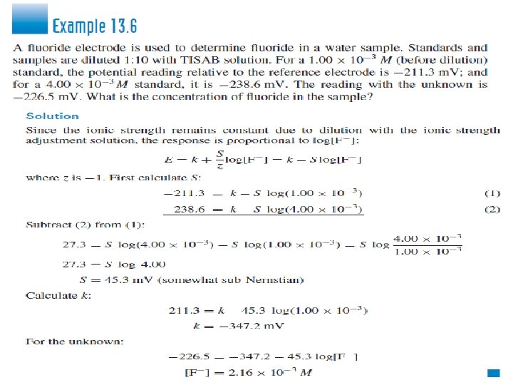
SOLID-STATE ELECTRODES 2 -The most successful example is the fluoride electrode. 3 - The membrane consists of a single crystal of lanthanum fluoride doped with some europium(II) fluoride to increase the conductivity of the crystal. 4 - Lanthanum fluoride is very insoluble, and this electrode exhibits Nerstian response to fluoride down to 10− 5 M and non -Nerstian response down to 10− 6 M 5 - This electrode has at least a 1000 -fold selectivity for fluoride ion over chloride, bromide, iodide, nitrate, sulfate, monohydrogen phosphate, and bicarbonate anions and a 10 fold selectivity over hydroxide ion. 6 - Hydroxide ion appears to be the only serious interference. The p. H range is limited by the formation of hydrofluoric acid at the acid end and by hydroxide ion response at the alkaline end; the useful p. H range is 4 to 9.
7 - Auseful solution for minimizing interferences with the fluoride electrode consists of a mixture of an acetate buffer at p. H 5. 0 to 5. 5, 1 M Na. Cl, and cyclohexylenedinitrilotetraacetic acid (CDTA) or TISAB. 8 - TISAB serves to adjust the ionic strength and the p. H, and to prevent Al 3+, Fe 3+, and Si 4+ from complexing the fluoride ion strength adjustment buffer). 9 - The buffer provides a p. H at which fluoride is almost entirely present as F− and hydroxide concentration is very low.
LIQUID—LIQUID ELECTRODES The basic construction of these electrodes is shown in Figure 13.
LIQUID—LIQUID ELECTRODES 1 - the potential- determining “membrane” is a layer of a waterimmiscible liquid ion exchanger held in place by an inert, porous membrane. 2 - The porous membrane allows contact between the test solution and the ion exchanger but minimizes mixing. It is either a synthetic flexible membrane or a porous glass frit, depending on the manufacturer. 3 - The internal filling solution contains the ion for which the ion exchanger is specific plus a halide ion for the internal reference electrode. 4 - An example : The calcium-selective electrode: The sensitivity of the electrode is governed by the solubility of the ion exchanger in the test solution. A Nernstian response is obtained down to about 5 × 10− 5 M. The selectivity of this electrode is about 3000 for calcium over sodium or potassium, 200 over magnesium, and 70 over strontium.
LIQUID—LIQUID ELECTRODES 5 - It can be used over the p. H range of 5. 5 to 11. 6 - Above p. H 11, calcium hydroxide precipitates. 7 - A phosphate buffer should not be used for calcium measurements because the calcium activity will be lowered by complexation or precipitation. 8 - These and other liquid-membrane electrodes are often subject to fouling, for example by protein adsoption in biological fluids.
PLASTIC MEMBRANE—IONOPHORE ELECTRODES 1 - It is type of electrode is that in which a neutral lipophilic (organic loving) ionophore that selectively complexes with the ion of interest is dissolved in a soft plastic membrane. 2 - The ionophore should be lipophilic (as opposed to hydrophilic) so that it is not leached from the membrane upon exposur to aqueous solutions. 3 - The plastic membrane is usually polyvinylchloride (PVC) based and consists of about 33% PVC; about 65% plasticizer, about 1. 5% ionophore. 4 - A solution of these components is prepared in a solvent such as tetrahydrofuran (THF) and then is poured onto a glass plate to allow the THF to evaporate. The pliable membrane that results can then be mounted at the end of an electrode body.
SELECTIVITY COEFFICIENT The potential of an ion-selective electrode in the presence of a single ion follows an equation similar to Equation 13. 38 for the p. H glass membrane electrode 13. 38 13. 44 where S represents the slope (theoretically 2. 303 RT/F=0. 059) z is the ion charge, including sign. Often, the slope is less than Nernstian; but for monovalent ion electrodes, it is usually close. The constant k depends on the nature of the internal reference electrode, the filling solution, and the construction of the membrane. It is determined by measuring the potential of a solution of the ion of known activity. Don’t forget the sign of z. log aion
SELECTIVITY COEFFICIENT 1 - If the electrode is in a solution containing amixture of cations (or anions, if it is an anion-responsive electrode), it may respond to the other cations (or anions). 2 - Example, we have a mixture of sodium and potassium ions and an electrode that responds to both. The Nernst equation must include an additive term for the potassium activity: ENa. K = k. Na + S log(a. Na+ + KNa. K+) The constant k. Na corresponds to that in the Nernst equation for the primary ion, sodium, alone. ENa. K is the potential of the electrode in a mixture of sodium and potassium. KNa. K is the selectivity coefficient of the electrode for potassium over sodium. KNa. K = 1/KKNa
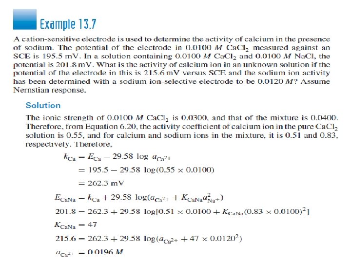
SELECTIVITY COEFFICIENT 3 - A general equation, called the Nikolsky equation, can be written for mixtures of two ions of different charges: where z. A is the charge on ion A and z. B is the charge on ion B. Thus, measurement of sodium in the presence of calcium using a sodium ion electrode would follow the expression:
SELECTIVITY COEFFICIENT 4 - Since all electrodes respond more or less to hydrogen ions, the practice is to keep the activity of the hydrogen ion low enough that the product in the Nikolsky equation is negligible. 5 -One problem with selectivity coefficients is that they often vary with the relative concentrations of ions and are not constant. For this reason, it is difficult to use them in calculations involving mixtures of ions. Selectivity coefficients are generally not sufficiently constant to use in quantitative calculations.
EXPERIMENTAL METHODS FOR DETERMINING SELECTIVITY COEFFICIENTS There are various methods to determine selectivity coefficients. These include the separate solution method, the fixed interference method, and the matched potential method.
MEASUREMENT WITH ION-SELECTIVE ELECTRODES 1 - As with p. H glass electrodes, most ion-selective electrodes have high resistance, and the measurement equipment must have high input impedance. 2 - A high resolution p. H meter is generally used. It is often necessary to pretreat ion-selective electrodes by soaking in a solution of the ion to be determined. 3 - The problems and accuracy limitations discussed under p. H and other direct potentiometric measurements apply also to ion-selective electrodes. 4 - A calibration curve of potential versus log activity is usually prepared.
Which one is correct answaer a) Ecell = Eleft− Eright b) Ecell =Eref − Eind c) Ecell = Eind − constant
a) p. H= 2. 41 b) p. H=5. 48 c) p. H=10. 1
Calculate the Ecell of reaction: H 2 O 2 + 2 e- = 2 OH- Eº= 0. 88 v Ce 4+ + e- = Ce 3+ Eº= 1. 61 v a)2. 49 b) 0. 73 v c)0. 022
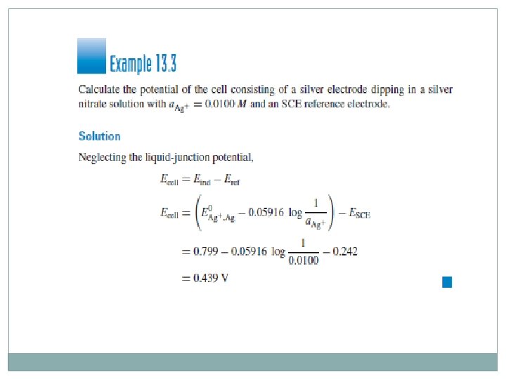
Calculate the Ecell contain (silver electrode and SCE =0. 242 v as reference electrode), the a. Ag+ = 0. 01 v a) 0. 439 v b) 1. 34 v c) 3. 22 v