Chapter 13 Lateral Earth Pressure Curved Failure Surface


 -")
 4.")
 Soil")
 Soil")
 Fig.")
 - Proposed the curved failure surface")


 FIGURE 13. 6")
 FIGURE 13. 7")

 - Two Types of Braced Cuts Soldier beam,")


- Slides: 32
Chapter 13 Lateral Earth Pressure – Curved Failure Surface 연세대학교 지반공학연구실 Soil Substructure Interaction Lab.
13. 1 Retaining Walls with Friction - In reality, retaining walls are rough shear forces develop bet/the face of the wall & the backfill - For practicality loose granular backfill dense granular backfill Soil Substructure Interaction Lab.
13. 1 Retaining Walls with Friction Soil Substructure Interaction Lab.
13. 1 Retaining Walls with Friction Soil Substructure Interaction Lab.
13. 1 Retaining Walls with Friction Soil Substructure Interaction Lab.
13. 1 Retaining Walls with Friction Figure 13. 1 Effect of wall friction on failure surface Soil Substructure Interaction Lab.
13. 2 Properties of a Logarithmic Spiral logarithmic spiral의 성질 Location of centroid Fig 13. 2 General parameters of a logarithmic spiral Soil Substructure Interaction Lab.
13. 3 Procedure for Determination of Passive Earth Pressure, Pp (Cohesionless Backfill ) - procedure of evaluating the passive resistance by trial wedges (Terzaghi & Peck. 1967) Steps 1. Draw retaining wall to a convinient scale 2. Draw line C 1 A (45 - /2) degrees with the surface of the backfill 3. Consider the stability of the soil mass ABC 1 C 1 for equilibrium) Rankine’s passive force F 1 = resultant of the shear and normal forces P 1 = passive force per unit length of the wall Soil Substructure Interaction Lab.
13. 3 Procedure for Determination of Passive Earth Pressure, Pp (Cohesionless Backfill ) 4. + 5. Trial passive force per unit length of the wall is repeated for several trial wedges 6. P 1 (trial wedge 1) P 2 (trial wedge 2) Plotted to a same scale P 3 (trial wedge n) • Find the low point of the smooth curve • That is actual passive force, Pp Soil Substructure Interaction Lab.
13. 3 Procedure for Determination of Passive Earth Pressure, Pp (Cohesionless Backfill ) Soil Substructure Interaction Lab.
13. 3 Procedure for Determination of Passive Earth Pressure, Pp (Cohesionless Backfill ) Soil Substructure Interaction Lab.
13. 3 Procedure for Determination of Passive Earth Pressure, Pp (Cohesionless Backfill ) Fig. 13. 3 Passive earth pressure against retaining wall with curved failure surface Soil Substructure Interaction Lab.
13. 4 Coeffi. of Passive Earth Pressure (Kp) - Proposed the curved failure surface like as arc. of a logarithmic spiral (Terzaghi & Peck, 1967 : Janbu, 1957) arc. of an ellipse (Caquot & Kerisel, 1948) ; Fig. 13. 4 , Table 13. 1 참조 arc. of a circle (Packshaw, 1969) Passive Presure by the Method of Slices by Shields and Tolunay (1973) Table 13. 2 참조 Example 13. 1 Soil Substructure Interaction Lab.
13. 5 Passive Force on Walls with Earthquake Forces FIGURE 13. 5 Logarithmic spiral failure surface for determination of Ppe Soil Substructure Interaction Lab.
13. 5 Passive Force on Walls with Earthquake Forces The passive force, Figure 13. 6 shows variation of with and for Mononobe-Okabe solution and for the logarithmic spiral Type of failure surface analysis. Soil Substructure Interaction Lab.
13. 5 Passive Force on Walls with Earthquake Forces ( ) FIGURE 13. 6 Variation of with and Soil Substructure Interaction Lab.
13. 5 Passive Force on Walls with Earthquake Forces ( ) FIGURE 13. 7 Variation of with and Soil Substructure Interaction Lab.
13. 5 Passive Force on Walls with Earthquake Forces As we can see from the figure, for a given value of the magnitude of , is always larger when the failure surface is assumed to be plane (Mononobe-Okabe solution) Soil Substructure Interaction Lab.
13. 6 Braced Cuts (버팀 굴착) - Two Types of Braced Cuts Soldier beam, wood lagging, wale, strut Sheetpile, wale, strut Figure 13. 8 Braced cut : (a) cross section ; (b) plan (section at X-X ) Soil Substructure Interaction Lab.
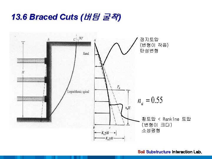
13. 7 Determination of Active Thrust on Bracing Systems of Open Cuts in Granular soil - Active thrust on the bracing system of open cuts : Terzaghi’s general wedge theory (1941) General Procedures 1. A point b 1 is selected. 2. From b 1, a line b 1 b 1 that makes an angle of with the ground surface is drawn. 3. The arc. of the logarithmic spiral, b 1 B is drawn with the center of the spiral (pt. O 1) 4. Consider the stability of the soil mass ABb 1 for equilibrium. W 1 = · area(ABb 1)·(1) P 1 = the active trust acting at a point na·H F 1 = the resultant of the shear and normal forces acting along with the trial failure surface. Soil Substructure Interaction Lab.
13. 7 Determination of Active Thrust on Bracing Systems of Open Cuts in Granular soil + 6. Trial active thrust is repeated for several trial wedges P 1 (trial wedge 1) P 2 (trial wedge 2) Plotted to a same scale Pn (trial wedge n) Find the maximum point of the smooth curve That is actual active force, Pa Soil Substructure Interaction Lab.
13. 7 Determination of Active Thrust on Bracing Systems of Open Cuts in Granular soil Substructure Interaction Lab.
13. 7 Determination of Active Thrust on Bracing Systems of Open Cuts in Granular soil Fig. 13. 12 Determination of active force on bracing system of open cut in cohesionless soil Substructure Interaction Lab.
13. 8 Determination of Active Thrust on Bracing Systems for Cuts in Cohesive Soil - Undrained condition, =0 The equation of the logarithmic spiral (circle) 1. Consider force for equilibrium of the wedge ABb 1 W 1 = · area(ABb 1)·(1) P 1 = the active trust acting at a height of na·H F 1 = the resultant acting along the surface of sliding cur 1 1 = force from cohesion acting along the surface of sliding ca. H = force from adhesion between the soil and the sheeting Soil Substructure Interaction Lab.
13. 8 Determination of Active Thrust on Bracing Systems for Cuts in Cohesive Soil 2. + 3. Trial active thrusts is obtained from several trial wedges P 1 (trial wedge 1) P 2 (trial wedge 2) Pn (trial wedge n) Plotted to a same scale the highest point of the smooth curve That is actual active thrust, Pa Soil Substructure Interaction Lab.
13. 8 Determination of Active Thrust on Bracing Systems for Cuts in Cohesive Soil Substructure Interaction Lab.
13. 8 Determination of Active Thrust on Bracing Systems for Cuts in Cohesive Soil Fig. (3 rd ed. ) Determination of active force on bracing system of open cut in cohesive soil( =0) Soil Substructure Interaction Lab.
13. 9 Pressure Variation for Design of Sheetings, Struts, and Wales - Calculation using general wedge theory does not explain the veriation of the earth PR with depth - Empirical lateral PR. diagrams (Peck, 1969) Fig. 13 Peck’s pressure diagrams for design of bracing systems Soil Substructure Interaction Lab.
13. 9 Pressure Variation for Design of Sheetings, Struts, and Wales - Limitation for Pressure Envelopes 1. PR. envelopes : apparent PR. envelopes 2. applied depth 20 ( 6 m) 3. W. T. : below the bottom of the cut 4. Sand : assumed th bd drained 5. Clay : assumed to be undrained and pwp is not considered Strut load determination - Soldier piles are assumed to be hinged at the strut level, except for the top & bottom ones - Strut loads Soil Substructure Interaction Lab.
13. 9 Pressure Variation for Design of Sheetings, Struts, and Wales Figure 13. 14 Determination of strut loads from empirical lateral pressure diagrams Example 13. 2 Soil Substructure Interaction Lab.
13. 10 Dynamic Earth Pressure Distribution Behind a Wall Rotating about the Top Figure 13. 17 Dynamic lateral earth pressure distribution behind a rigid model retaining wall rotating Soil Substructure Interaction Lab.