Chapter 13 Concrete Form Design Concrete Form Design


 for an elevated concrete")


 12 in. •")


 lumber • Joists: 2 x")
- Slides: 31
Chapter 13 Concrete Form Design
Concrete Form Design • SLAB FORM DESIGN Method • WALL AND COLUMN FORM DESIGN • DESIGN OF LATERAL BRACING
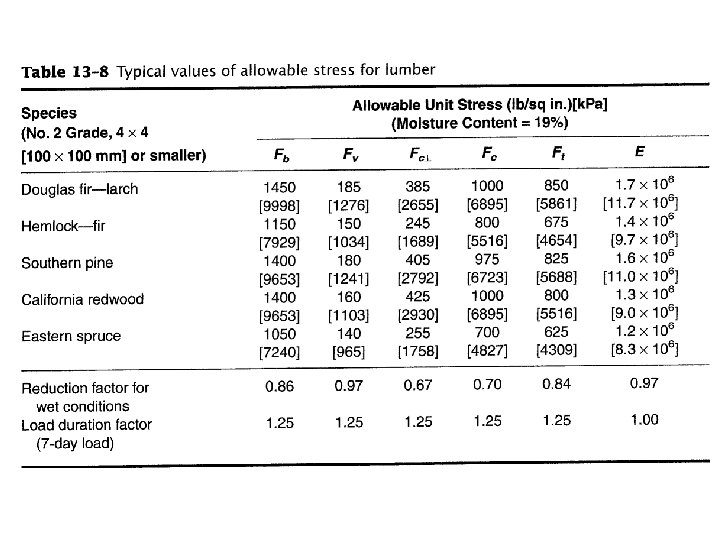
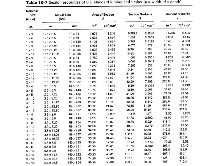
EXAMPLE 13 -1 • Design the formwork (Figure 13 -2) for an elevated concrete floor slab 6 in. (152 mm) thick. • Sheathing will be nominal I-in. (25 -mm) lumber while 2 x 8 in. (50 x 200 mm) lumber will be used for joists. • Stringers will be 4 x 8 in. (100 x 200 mm) lumber. • Assume that all members are continuous over three or more spans. • Commercial 4000 -lb (17. 8 -k. N) shores will be used. • It is estimated that the weight of the formwork will be 5 lb/sq ft • (0. 24 k. Pa). • The adjusted allowable stresses for the lumber being used are as follows:
EXAMPLE 13 -1 • Maximum deflection of form members will be limited to 11360. • Use the minimum value of live load permitted by ACI. • Determine joist spacing, stringer spacing, and shore spacing.
Solution
Figure 13 -2 Slab form
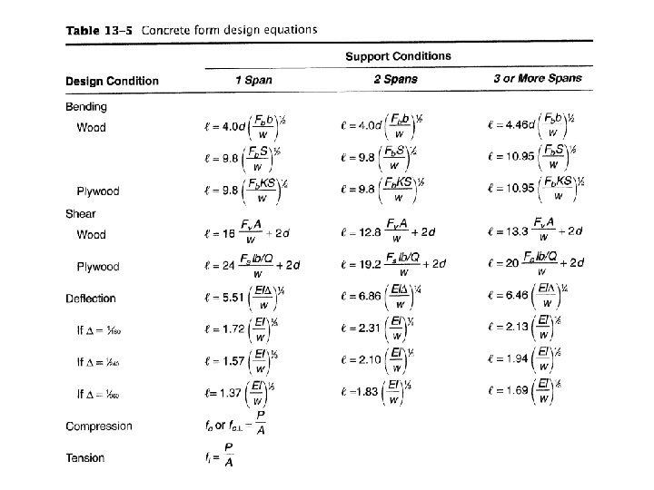
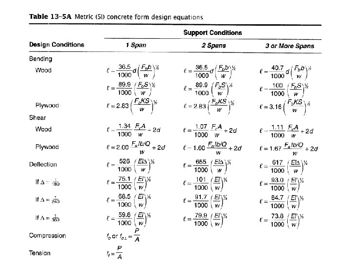
Deck Design • Consider a uniformly loaded strip of decking (sheathing) 12 in. • (or 1 m) wide placed perpendicular to the joists (Figure 13 -1 a) and analyze it as a beam. • Assume that the strip is continuous over three or more spans and use the appropriate equations of Table 13 -5 and 13 -5 A. • w =(1 sq ft/lin ft) x (130 lb/sq ft) = 130 lb/ft • [w =(1 m 2/m) x (6. 21 k. N/m 2) =6. 21 k. N/m]
Figure 13 -1 Design Analysis form member
Deck Design
Deck Design
Deck Design
• Deflection governs in this case and the maximum allowable span is 27. 7 in. (703 mm). • We will select a 24 -in. (610 -mm) joist spacing as a modular value for the design.
Joist design • Consider the joist as a uniformly loaded beam supporting a strip of design load 24 in. (610 mm) wide (same as joist spacing; see Figure 13 -1 b). • Joists are 2 x 8 in. (50 x 200 mm) lumber. • Assume that the joists are continuous over three spans. • w =(2 ft) x (130 lb/sq ft) =260 lb/ft • [ w =(0. 610 m) x (1) x (6. 22 k. Pa) = 3. 79 k. N/m]
Figure 13 -1 Design Analysis form member
Joist design
Joist design
Joist design
Joist design • Thus bending governs and the maximum joist span is 87 in. (2213 mm). • We will select a stringer spacing (joist span) of 84 in. (2134 mm).
Stringer Design • To analyze stringer design, consider a strip of design load 7 ft (2. 13 m) wide (equal to stringer spacing) as resting directly on the stringer (Figure 13 -1 c). • Assume the stringer to be continuous over three spans. • Stringers are 4 x 8 (100 x 200 mm) lumber. • Now analyze the stringer as a beam and determine the maximum allowable span. • w =(7) (130) =910 lb/ft • [w =(2. 13) (1) (6. 22) = 13. 25 k. N/m]
Figure 13 -1 Design Analysis form member
Stringer Design
Stringer Design
Stringer Design • Bending governs and the maximum span is 71. 1 in. (1808 mm).
Check Shore Strength • Now we must check shore strength before selecting the stringer span (shore spacing). • The maximum stringer span based on shore strength is equal to the shore strength divided by the load per unit length of stringer. • Thus the maximum stringer span is limited by shore strength to 52. 7 in. (1. 343 m). • We select a shore spacing of 4 ft (1. 22 m) as a modular value.
Check for Crushing • Before completing our design, we should check for crushing at the point where each joist rests on a stringer. • The load at this point is the load per unit length of joist multiplied by the joist span.
Final Design • Decking: nominal 1 -in. (25 -mm) lumber • Joists: 2 x 8's (50 x 200 -mm) at 24 -in. (610 mm) spacing • Stringers: 4 x 8's (100 x 200 -mm) at 84 -in. (2. 13 -m) spacing • Shore: 4000 -lb (17. 8 -k. N) commercial shores at 48 -in. (1. 22 -m) intervals