Chapter 11 Dimensioning Instructor M Yaqub There are

Chapter 11 Dimensioning Instructor: M. Yaqub

• There are certain rule to indicate dimension on drawing. This chapter about these rules. • Follow these rules when indicate dimension. • A drawing must contains all necessary dimension. Dimension should not repeat. • SI system is being used now a days. • ANSI American National Standard Institute • ISO International Standard Organization

Size Description • In addition to complete shape description of an object, a complete size description is also required for manufacturing. • The increasing need for precision manufacturing and the necessity of controlling sizes for interchange-ability has shifted responsibility for size control to the designing engineer and the drafter.

Scale of Drawing • Drawing should be made to scale, and the scale should be indicated in the title. • A heavy straight line should be drawn under any dimension that is not to scale, or the abbreviation NTS (not to scale) should be indicated.

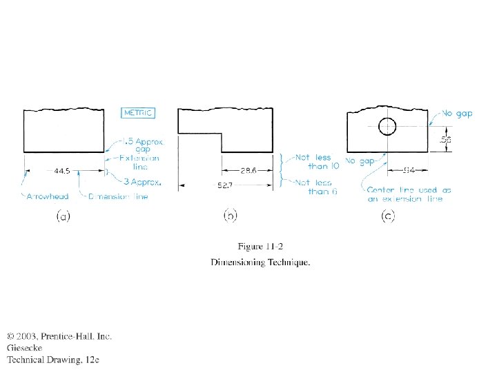
Learning to Dimension • • • Student must learn Technique of dimension Placement of dimension Choice of dimension Line use in dimensioning (Figure 11. 2)

Lines used in dimensioning • Dimension line is a thin dark solid line terminated by arrow heads which indicates the direction and extent of dimension. • Extension line is a thin dark solid line extends from a point on the drawing to which a dimension refers. • Center line is thin dark line has long and short dashes and represent axis. Always ends on a long dash.

Placement of dimension and extension line
 Dimension lines")
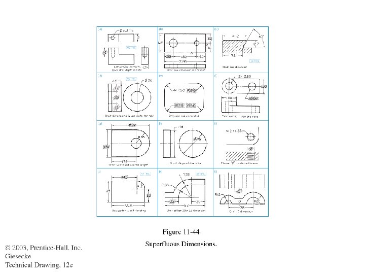
The shorter dimensions are nearest to the object outline. (11. 3 a) Dimension lines should not cross extension line. (11. 3 b)
")
Don’t make extension line short. It may cut another extension line (11. 3 c) A dimension line never coincide with or form a continuation of any line of drawing (11. 3 d)

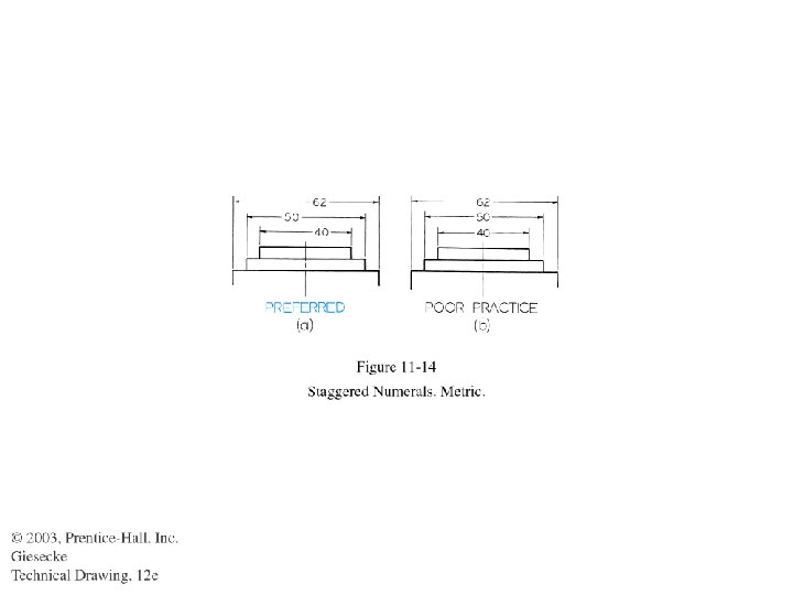
Dimension should be line up or group together

No gap when extension line or center line cross the visible line
")
Usually dimension line normal to extension line but exception as in (a)

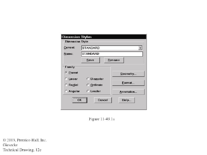
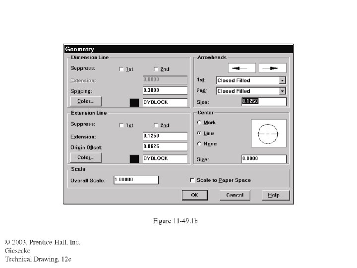
Arrow heads should be uniform in size and style through out the drawing Can select from the software

A leader is a thin solid line leading from a note or dimension and terminating in an arrowhead or a dot touching the part to which attention is directed. Leaders should cross few lines and never each other. In bend leaders, angle 30 – 60 degree.

Dual dimension Position method Drawing should indicate MILIMETER/INCH mm above and inch below or right and left.
![Dual Dimension Bracket Method mm dimension in [ ] and uniform on the drawing.](http://slidetodoc.com/presentation_image_h2/47582952572cc042a1de62a3916592e8/image-25.jpg "Dual Dimension Bracket Method mm dimension in [ ] and uniform on the drawing.")
Dual Dimension Bracket Method mm dimension in [ ] and uniform on the drawing. Include a note DIMENSIONS IN [ ] ARE IN MILIMETERS

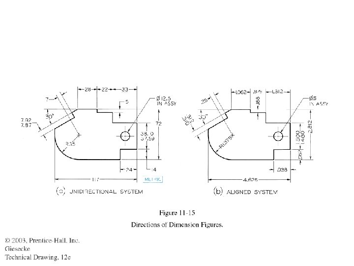
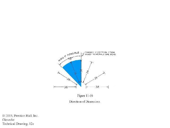
Direction of Dimension Figure • Two systems of reading direction for dimension figures are available. • Unidirectional System: All dimensions figures and notes are lettered horizontally on the sheet. • Aligned System: All dimensions figures are aligned with the dimension lines.
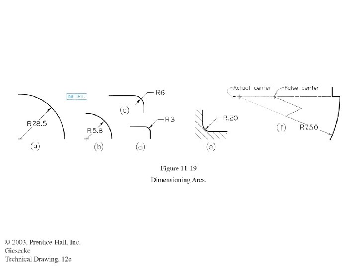
 more accurate")
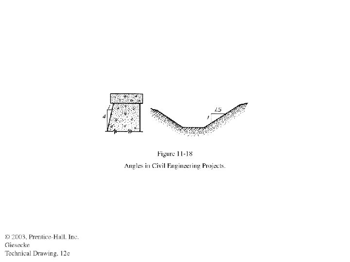
Dimensioning Angles Fig (b) more accurate

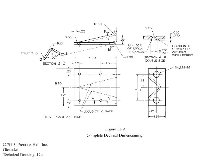
Fillet and Rounds • FILLET AND ROUNDS R 5 UNLESS OTHERWISE SPECIFIED. • ALL FILLET AND ROUNDS R 5

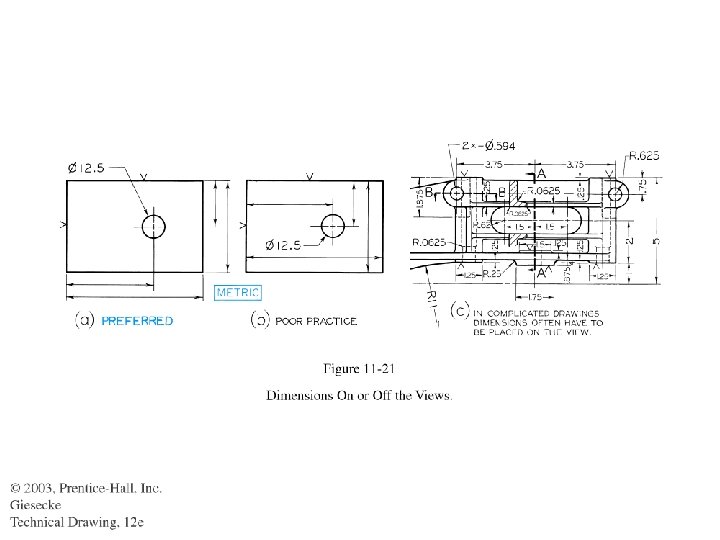
DIMENSIONS ON OR OFF VIEW • Dimensions should not place on the view Fig 11. 21 a. • Placement of dimensions on the view is a poor practice Fig 11. 21 b. • It does not mean that dimensions never be placed on the view Fig 11. 21 c. • Place dimensions outside of views, except where directness of application and clarity are gained by features dimensioned.

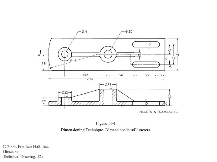
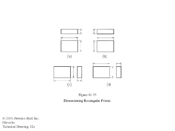
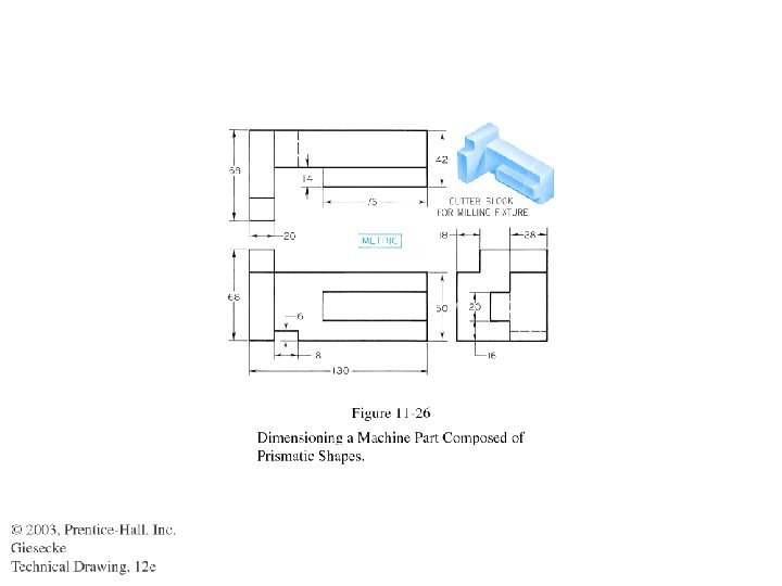
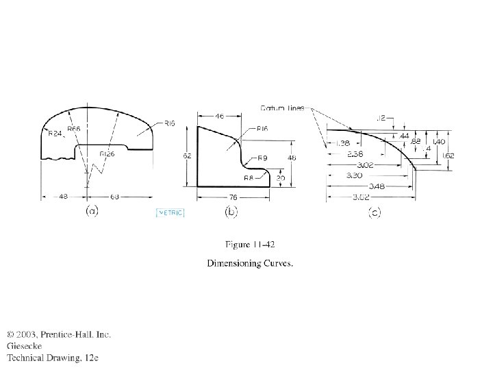
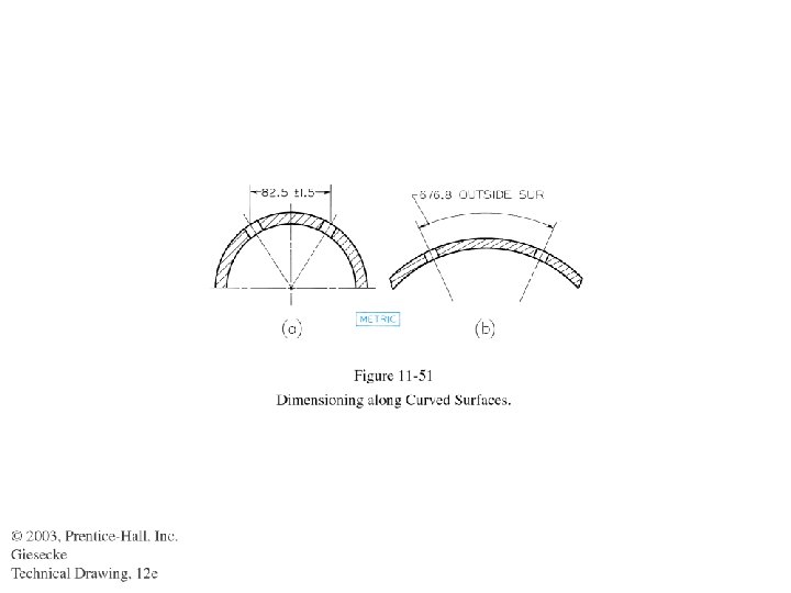
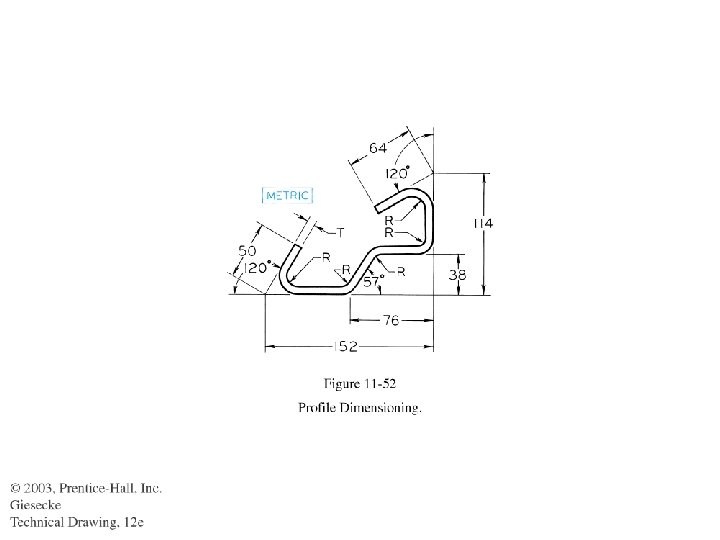
Contour dimension

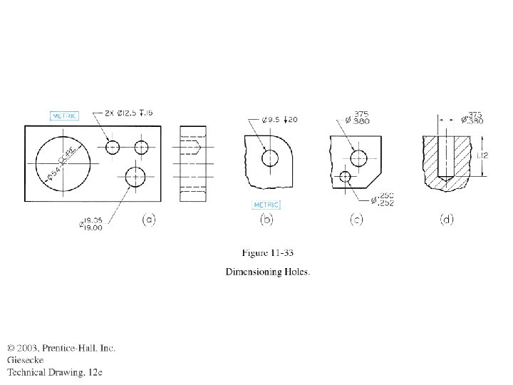
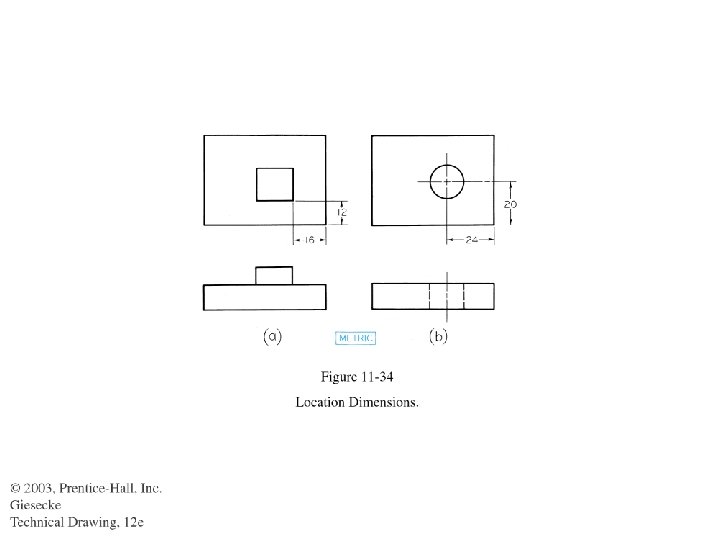
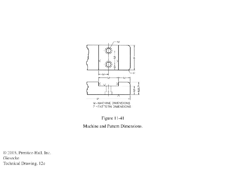
Size dimension: show size of the geometry. Location dimension: Give dimensions locating with respect to each other.
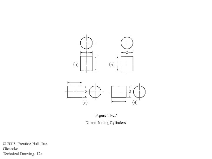

Use “Phi” for diameter dimension
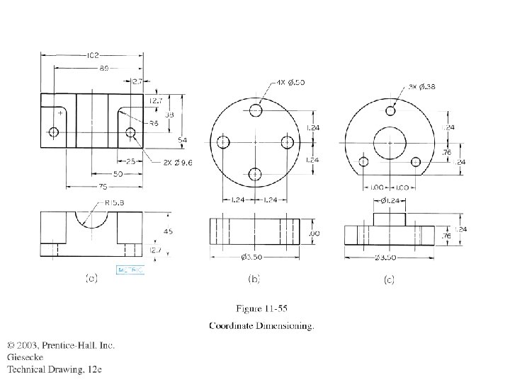
, bolt dia is a reference dimension")
In (C), bolt dia is a reference dimension

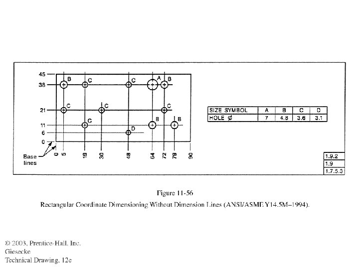
Coordinate dimension and linear dimension

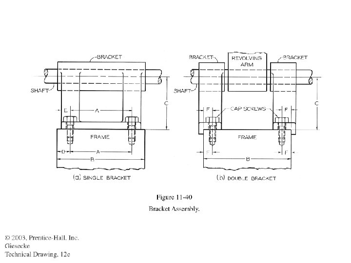
Mating dimension: common in both pats
 • Notes should be brief, lettered horizontally on the sheet and")
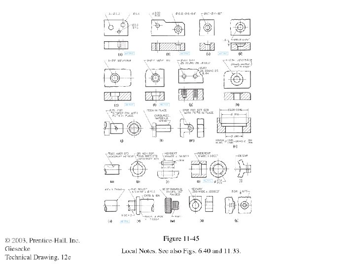
Notes (General Notes) • Notes should be brief, lettered horizontally on the sheet and systematic manner. • Don’t place at crowded places or in between the views if possible. • For example. FINISH ALL OVER (FAO) DIMENSIONS APPLY AFTER PLATING See page a 21 (Appendix for more detail)

Chamfer dimension
- Slides: 75