Chapter 10 Refrigeration Cycle References Reference Cengel Yunus


 can be used")


- Slides: 40
Chapter 10 Refrigeration Cycle References: • Reference: Cengel, Yunus A. and Michael A. Boles, Thermodynamics: An Engineering Approach, 5 th ed. , New York, Mc. Graw-Hill: 2006 • Sonntag R. E. , and Van Wylen G. J. , Introduction to Thermodynamics: Classical and Statistical, 3 rd Ed. , John Wiley & Sons, 1991 Westminster, London, UK Assoc. Prof. Sommai Priprem, Ph. D. Department of Mechanical Engineering Khon Kaen University
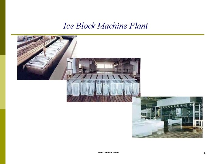
Introduction • Refrigeration Cycle is a kind of Heat Pump. • There are many type of refrigeration device, ie. : • Vapor Compression refrigeration • Gas refrigeration • Absorbtion refrigeration • Thermoelectric refrigeration • Vapor Compression Refrigeration is commonly used now a day • 1834 Jacob Perkins patented “ Ice Machine” • 1850 Alexander Twining commercial “Ice Machine” รศ. ดร. สมหมาย ปรเปรม 2
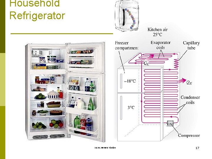
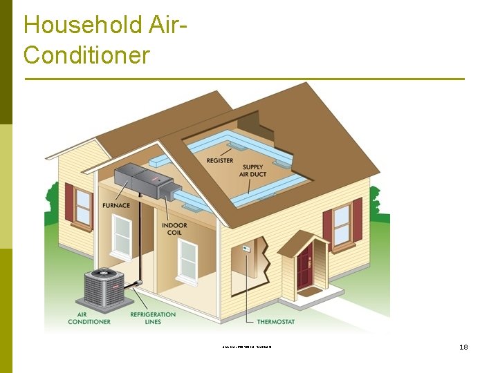
Application in domestic used A Freezer A Refrigerator An Ice Maker A Refrigerator with Freezer รศ. ดร. สมหมาย ปรเปรม 3
Chillers of a Central Air Conditioning System รศ. ดร. สมหมาย ปรเปรม 4
Automobiles Air Conditioning System รศ. ดร. สมหมาย ปรเปรม 5
Some Important Terms Air Conditioner, Refrigerator, Freezer, Ice Maker, Heat Pump p Refrigerants: CFCs: R-12, R-22, R-134 a, . . . NH 3, Hydrocarbons: propane, ethelene. . . CO 2 Air, Water p Coefficient of performance, COP. Energy Efficiency Ratio, EER (Btu/W-hr) p 1 Ton of Refrigeration = Qremove from 1 ton(2, 000 lb) of WATER p at 32 F to be ICE at 32 F in 24 hr 1 Ton = 12, 000 Btu/h = 3. 517 k. W รศ. ดร. สมหมาย ปรเปรม 7
Recall from chapter 5 The Second Law of Thermodynamics
Refrigerator and Heat Pump A Simple Vapor-Compression Refrigeration has 4 devices and performs 4 processes in a cycle: 1. Compressor: compress vapor to high Press. (HP) 2. Condenser: condense HP vapor to HP liq. 3. Expansion Valve: reduces pressure of HP liq. to LP 4. Evaporator: receive heat from low temp body LP liq. vaporizes to LP vap. รศ. ดร. สมหมาย ปรเปรม Environment QH Condenser Expansion Valve Win Compressor Evaporator QL Refrigerated Space 9
Refrigerator and Heat Pump 3 Condenser Expansion Valve 4 2 Compressor Evaporator รศ. ดร. สมหมาย ปรเปรม 1 10
House-heating using House-cooling using an air-conditioner a Heating at 20 o. C Environment 40 heat pump o. C QH 50 o. C Condenser 30 80 o. C Expansion Valve QH o. C Condenser Expansion Valve Win Compressor 10 Evaporator o. C 80 o. C Compressor 15 o. C Evaporator -20 o. C QL -10 o. C Out dooe space Air Conditioned, 25 o. C รศ. ดร. สมหมาย ปรเปรม 11
Coefficient of Performance COP = desired output = Quseful required input Win COPR = QL = Win QL = QH-QL 1. QH/QL- 1 COPHP = QH = Win QH = QH-QL 1. 1 -QL/QH รศ. ดร. สมหมาย ปรเปรม (5. 5) (5. 6) 12
The Second Law of Thermodynamics: Clausuis Statement It is impossible to construct a device that operates in a cycle and produces no effect other than the transfer of heat from a lower-temperature body to a higher-temperature body. High-Temp. Body, TH Q Low-Temp. Body, TL High-Temp. Body, TH meaning: W > 0 from COP = QH Q W No heat pump can have a COP of รศ. ดร. สมหมาย ปรเปรม Heat Pump W QL Low-Temp. Body, TL 13
Reverse Carnot Cycle = Carnot Heat Pump T-s Diagram WARM medium at TH 3 T QH P 2 2 Condenser Turbine QH 3 Compressor 2 P 1 Win 1 4 4 1 QL Evaporator s QL COLD medium at TL รศ. ดร. สมหมาย ปรเปรม 14
Vapor Compression Refrigeration Cycle The cycle widely used in the world for cooling, freezing, and heating
4 - Processes Process 1 -2 Isentropic Compression Process, s=const. : Compressor, sat. vap superheat vapor Process 2 -3 P = const. Heat Rejection Process: Process Condenser, superheat vapor sat. liquid Process 3 -4 Throttling Process, h=const. : Expansion Valve, sat. liquid mixture Process 4 -1 P = const. Heat Addition Process : Evaporator, Mixture sat. vapor Schematic Diagram T-s Diagram Environment T QH P 2 2 Condenser 2 3 3 Expansion Valve Compressor Win QH P 1 Win 4 1 Evaporator QL QL s Refrigerated Space รศ. ดร. สมหมาย ปรเปรม 16
Fan Coil Unit Evaporator Tube Condensing Unit รศ. ดร. สมหมาย ปรเปรม 19
P-h Diagram is more appropriate than P-v dia. T-s Diagram T P-h Diagram P P 2 2 3 Win QH QH 3 2 P 1 Win P 1 1 4 4 QL s h 4= h 1 รศ. ดร. สมหมาย ปรเปรม QL 1 h 2 h 20
Example 10 -1 A refrigerator uses refrigerant-12 as the working fluid and operates on an ideal vaporcompression refrigeration cycle between 0. 14 and 0. 8 MPa. The mass flow rate of the refrigerant is 0. 05 kg/sec. Show the cycle on a T-s diagram with respect to saturation lines. Determine (a) the rate of heat removal from the refrigerated space and the power input to the compressor, (b) the rate of heat rejection to the environment and (c) the coefficient of performance. T T-s Diagram Environment P 2 QH 3 Win 0. 8 MPa Condenser 2 3 P 1 Expansion Valve 0. 14 MPa 4 Evaporator 1 4 QL Compressor Win 1 QL mdot = 0. 05 kg/s Refrigerated Space s R-12 Property: Table A-11 – A-12 State 1 sat. vap. @ P 1 = 0. 14 MPa h 1 = hg@P 1 = 177. 87 k. J/kg, s 1 = sg = 0. 7102 k. J/kg-K State 2 P 2 = 0. 8 MPa and s 2 = s 1 = 0. 7102 k. J/kg-K, h 2 = 208. 65 k. J/kg (T 2 = 43. 5 C) 3 State 3 sat. liq. and P 3 = P 2= 0. 8 MPa, h 3 = hf@P 3 = 67. 3 k. J/kg State 4 h 4 = h 3 = 67. 3 k. J/kg (Throttling Process) รศ. ดร. สมหมาย ปรเปรม Expansion Valve 4 21
4 1 Evaporator QL 2 Compressor Win 1 QH 3 2 Condenser รศ. ดร. สมหมาย ปรเปรม 22
Example 10 -2 Refrigerant-12 enters the compressor of a refrigerator as superheated vapor at 0. 14 MPa and 50 o. C. The refrigerant is cooled in the condenser to 26 o. C and 0. 72 MPa, and is throttled to 0. 15 MPa. Disregarding any heat transfer and pressure drops in the connecting lines between the components, determine (a) the rate of heat removal from the refrigerated space and the power input to the compressor, (b) the adiabatic efficiency of the compressor, and (c) the coefficient of performance of the refrigerator. T-s Diagram 2 T 2 s P 3 = 0. 72 MPa T 3 = 26 o. C P 2 = 0. 8 MPa T 2 = 50 o. C QH Win 3 P 1 = 0. 14 MPa T 1 = -20 o. C P 4 = 0. 15 MPa 1 4 R-12 Property: Table A-11 – A-12 State 1 superheated. vap. P 1 = 0. 14 MPa and T 1 = -20 C h 1 = 179. 01 k. J/kg State 2 superheated. vap. P 2 = 0. 8 MPa and T 2 = 50 C h 2 = 213. 45 k. J/kg State 3 Compressed. liq. P 3 = 0. 72 MPa, and T 3 = 26 C h 3 = hf@26 C = 60. 68 k. J/kg State 4 h 4 = h 3 = 60. 68 k. J/kg (Throttling Process) QL s รศ. ดร. สมหมาย ปรเปรม 23
4 1 Evaporator QL 2 Compressor Win 1 รศ. ดร. สมหมาย ปรเปรม 24
Cascade Refrigeration Systems Some industrial applications require moderately low temperatures, and the temperature range they involve may be too large for a single vapor-compression refrigeration cycle to be practical. The solution is cascading. Cascading improves the COP of a refrigeration system. Some systems use three or four stages of cascading. A two-stage cascade refrigeration system รศ. ดร. สมหมาย ปรเปรม with the same refrigerant in both stages. 26
Multistage Compression Refrigeration Systems When the fluid used throughout the cascade refrigeration system is the same, the heat exchanger between the stages can be replaced by a mixing chamber (called a flash chamber) since it has better heat transfer characteristics. A two-stage compression refrigeration รศ. ดร. สมหมาย ปรเปรม a flash chamber. system with 27
Multipurpose Refrigeration Systems with a Single Compressor Some applications require refrigeration at more than one temperature. A practical and economical approach is to route all the exit streams from the evaporators to a single compressor and let it handle the compression process for the entire system. Schematic and T-s diagram for a refrigerator–freezer unit with one compressor. รศ. ดร. สมหมาย ปรเปรม 28
Liquefaction of Gases Many important scientific and engineering processes at cryogenic temperatures (below about 100°C) depend on liquefied gases including the separation of oxygen and nitrogen from air, preparation of liquid propellants for rockets, the study of material properties at low temperatures, and the study of superconductivity. The storage (i. e. , hydrogen) and transportation of some gases (i. e. , natural gas) are done after they are liquefied at very low temperatures. Several innovative cycles are used for the liquefaction of gases. Linde-Hampson system รศ. ดร. สมหมาย ปรเปรม for liquefying gases. 29
GAS REFRIGERATION CYCLES The reversed Brayton cycle (the gas refrigeration cycle) can be used for refrigeration. Simple gas refrigeration cycle. รศ. ดร. สมหมาย ปรเปรม 30
The gas refrigeration cycles have lower COPs relative to the vaporcompression refrigeration cycles or the reversed Carnot cycle. The reversed Carnot cycle consumes a fraction of the net work (area 1 A 3 B) but produces a greater amount of refrigeration (triangular area under B 1). An open-cycle aircraft cooling system. Despite their relatively low COPs, the gas refrigeration cycles involve simple, lighter components, which make them suitable for aircraft cooling, and they can incorporate regeneration รศ. ดร. สมหมาย ปรเปรม 31
Without regeneration, the lowest turbine inlet temperature is T 0, the temperature of the surroundings or any other cooling medium. With regeneration, the high-pressure gas is further cooled to T 4 before expanding in the turbine. Lowering the turbine inlet temperature automatically lowers the turbine exit temperature, which is the minimum temperature in the cycle. Extremely low temperatures can be achieved by repeating regeneration process. Gas refrigeration cycle with regeneration. รศ. ดร. สมหมาย ปรเปรม 32
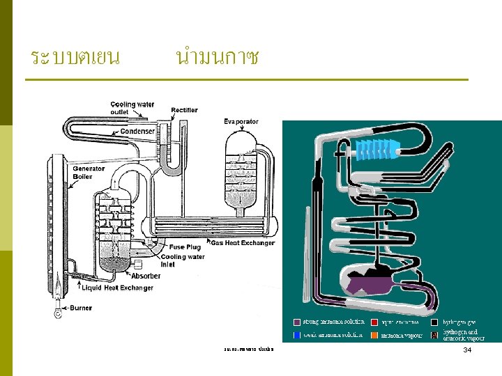
ABSORPTION REFRIGERATION SYSTEMS When there is a source of inexpensive thermal energy at a temperature of 100 to 200°C is absorption refrigeration. Some examples include geothermal energy, solar energy, and waste heat from cogeneration or process steam plants, and even natural gas when it is at a relatively low price. Ammonia absorption refrigeration cycle. รศ. ดร. สมหมาย ปรเปรม 33
Some Selected Problems
The Reverse Carnot Cycle 10 -5 Refrigerant-12 enters the condenser of a steady-flow Carnot refrigerator as a saturated vapor at 800 k. Pa and leaves with a quality of 0. 05. The heat absorption from the refrigerated space takes place at 140 k. Pa. Show the cycle on a T -s diagram relative to saturation lines, and determine (a) the coefficient of performance, (b) the quality at the beginning of the heat absorption process, and (c) the net work input. Answers: (a) 4. 59, (b) 0. 317, (c) 22. 7 k. J/kg Ideal and Actual Vapor-Compression Refrigeration Cycles 10 -6 C Does the ideal vapor-compression refrigeration cycle involve any internal irreversibilities? 10 -7 C Why is the throttling valve not replaced by an isentropic turbine in the ideal vapor-compression refrigeration cycle? 10 -8 C It is proposed to use water instead of refrigerant-12 as the working fluid in air conditioning applications, where the minimum temperature never falls below the freezing point. Would you support this proposal? Explain. 10 -9 C In a refrigeration system, would you recommend condensing the refrigerant-12 at a pressure of 0. 7 or 1. 0 MPa if heat is to be rejected to a cooling medium at 15°C? Why? รศ. ดร. สมหมาย ปรเปรม 36
10 -10 C Does the area enclosed by the cycle on a T-s diagram represent the net work input for the reversed Carnot cycle? How about for the ideal vaporcompression refrigeration cycle? 10 -11 C Consider two vapor-compression refrigeration cycles. The refrigerant enters the throttling valve as a saturated liquid at 30°C in one cycle and as sub cooled liquid at 30°C in the other one. The evaporator pressure for both cycles is the same. Which cycle do you think will have a higher COP? 10 -l 2 C The COP of vapor-compression refrigeration cycles improves when the refrigerant is subcooled before it enters the throttling valve. Can the refrigerant be subcooled indefinitely to maximize this effect, or is there a lower limit? Explain. 10 -13 A refrigerator uses refrigerant-12 as the working fluid and operates on an ideal vapor-compression refrigeration cycle between 0. 12 and 0. 7 MPa. The mass flow rate of the refrigerant is 0. 05 kg/sec Show the cycle on a T-s diagram with respect to saturation lines. Determine (a) the rate of heat removal from the refrigerated space and the power input to the compressor, (b) the rate of heat rejection to the environment and (c) the coefficient of performance. answer: (0) 5. 68 k. W, 1. 55 k. W; (b) 7. 24 k. W; (c) 3. 67 รศ. ดร. สมหมาย ปรเปรม 37
10 -14 If the throttling valve in Prob. 10 -13 is replaced by an isentropic turbine. determine the percentage increase in the COP and in the rate of heat removal from the refrigerated space. answers: , 4. 6 percent 10 -15 Consider a 300 k. J/min refrigeration system which operates on an ideal vapor-compression refrigeration cycle with refrigerant-12 as the working fluid. The refrigerant enters the compressor as saturated vapor at 140 k. Pa and is compressed to 800 k. Pa. Show the cycle on a T-s diagram with respect to saturation lines, and determine (a) the quality of the refrigerant at the end of the throttling process, (b) the coefficient of performance, and (c) the power input to the compressor. 10 -16 Repeat Prob. 10 -15 assuming an adiabatic efficiency of 85 percent for the compressor. Also determine the irreversibility rate associated with the compression process in this case. Take To = 298 K. รศ. ดร. สมหมาย ปรเปรม 38
10 -17 Refrigerant-12 enters the compressor of a refrigerator as superheated vapor at 0. 14 MPa and -20°C at a rate of 0. 04 kg/s, and it leaves at 0. 7 MPa and 50°C. The refrigerant is cooled in the condenser to 24°C and 0. 65 MPa, and it is throttled to 0. 15 MPa. Disregarding any heat transfer and pressure drops in the connecting lines between the components. show the cycle on a T-s diagram with respect to saturation lines, and determine (a) the rate of heat removal from the refrigerated space and the power input to the compressor, (b) the adiabatic efficiency of the compressor. and (c) the COP of the refrigerator. Answer: (a) 4. 81 k. W, 1. 44 k. W; (b) 79. 4 percent; (c) 3. 34 10 -18 An ice-making machine operates on the ideal vapor-compression cycle using refrigerant-12. The refrigerant enters the compressor as saturated vapor at 160 k. Pa and leaves the condenser as saturated liquid at 700 k. Pa. Water enters the ice machine at 15°C and leaves as ice at -5°C. For an ice production rate of 12 kg/h, determine the power input to the ice maker (384 k. J of heat needs to be removed from each kilogram of water at 15°C to turn it into ice at -5°C). Answer: 0. 284 k. W รศ. ดร. สมหมาย ปรเปรม 39
End of Chapter 10 ขอใหทกคนทำได ดด ในการสอบไล Wall Street, New York, USA End of Thermodynamics 1