Chapter 10 Establishing Frame Relay Connections v Frame

Chapter 10 Establishing Frame Relay Connections v Frame Relay Overview v Configuring Frame Relay 1
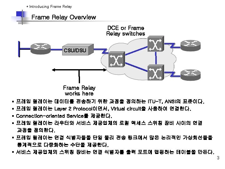

* Frame Relay Stack Layered Support Frame Relay Stack OSI Reference Model Frame Relay Application Presentation Session Transport Network IP/IPX/Apple. Talk, etc. Data Link Frame Relay Physical EIA/TIA-232, EIA/TIA-449, V. 35, X. 21, EIA/TIA-530 § Frame Relay 는 Data Link Layer에서 작동한다. § Frame Relay 는 Multiple Upper-Layer Protocol을 지원한다. § OSI 스택의 상위 계층에서부터 오는 정보를 캡슐화한다. 4
 Address :")
Frame Relay Format § § § opening flags (0 x 7 E) Address : 10 bits circuit identifier, 6 bits congestion management Data : encapsulated upper-layer data FCS (frame check sequence) : 에러 check 기능 closing flags (0 x 7 E) 5

* Frame Relay Terminology PVC Router A DLCI: 100 Router B DLCI: 200 LMI 100 = Active 400 = Active Branch Central Local Access Loop = 64 Kbps DLCI: 400 Local Access Loop = T 1 PVC DLCI: 500 Branch Local Access Loop = 64 Kbps Router C 6
 Ø 프레임 릴레이 용어 § Be(Excess Burst) : CIR을")
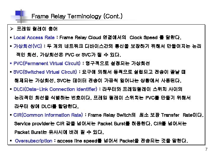
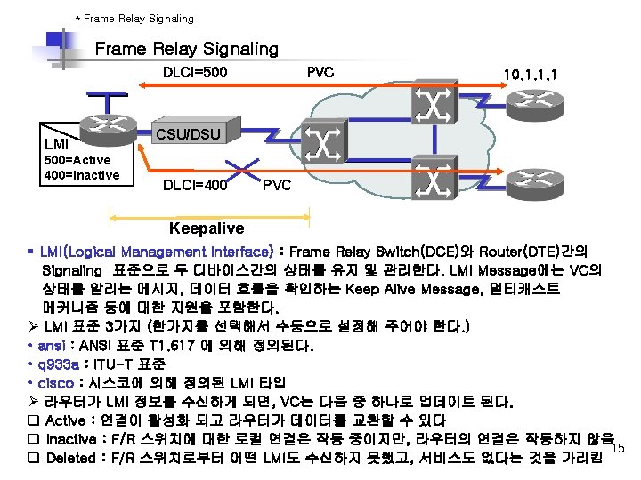
Frame Relay Terminology (Cont. ) Ø 프레임 릴레이 용어 § Be(Excess Burst) : CIR을 넘어서 Frame Relay Switch가 Transfer하는 Rate이다. § Bc(Committed Burst) : Frame Relay Switch 가 Transfer 해 줄 수 있는 최대 Transfer Rate이다 § DE(Discard Eligibility) : Router가 CIR을 넘어서는 Traffic에 대해서 설정하는 bit로 , Network Congestion의 경우, FR Switch는 DE bit가 설정된 Packet을 먼저 drop 시킨다. § IARP(Inverse Address Resolution Protocol) : 네트워크 계층 주소를 DLCI와 동적으로 연관시키는 방법이다. 이것은 라우터가 VC와 연관된 디바이스의 네트워크 계층 주소를 발견하도록 한다. § LMI(Local Management Interface) : 라우터 와 F/R Switch간의 연결과 유지 상태를 관리하는 책임을 가지는 F/R간의 시그널링 표준이다. § FECN(Forward Explicit Congestion Notification) : frame relay switch가 congestion을 인지한 경우, Destination Device에 보내는 Message이다. § BECN(Backward Explicit Congestion Notification) : frame relay switch가 congestion을 인지한 경우, Source Router에 보내는 Message이다. 8

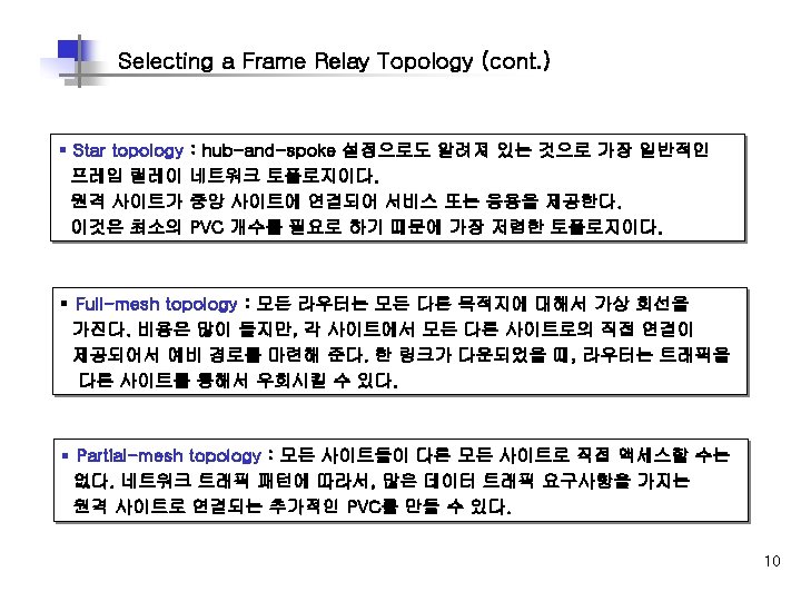
* Frame Relay Topologies Selecting a Frame Relay Topology Full mesh Partial mesh Star (hub and spoke) 9

* Resolving Reachability Issues in Frame Relay Reachability Issues with Routing Updates Routing update A 1 2 Circuit #21 B B Circuit #22 10. 16. 0. 2 CC 10. 16. 0. 1 3 Circuit #23 10. 16. 0. 3 D D 10. 16. 0. 4 § Frame Relay issues ü Broadcast traffic은 모든 Active connection에 복제 되어야 한다. ü 프레임 릴레이가 단일 인터페이스에서 여러 PVC를 작동시키고 있다면, 주된 문제는 Split horizon이다 11
 § Frame Relay Network 은 Nonbroadcast Mulitaccess")
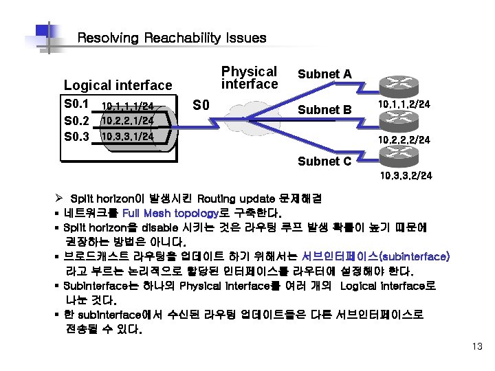
Reachability Issues with Routing Updates (cont. ) § Frame Relay Network 은 Nonbroadcast Mulitaccess (NBMA) network이다. - 프레임 릴레이 스위치는 단일 DLCI로 부터 들어오는 브로드캐스트 패킷을 모든 DLCI 로 복제하지 않기 때문에 nonbroadcast라고 부른다. § Frame Relay Interface는 Multipoint Connection을 지원한다. PVC간에 Broadcast가 되지 않는 관계로 Multiple PVC가 하나의 Interface에 연결되는 경우는 라우터간에 발생하는 Routing Update에 문제가 생긴다. 하나의 Interface에 하나의 PVC만을 사용 하는 경우에는 문제가 없다. § Split horizon은 한 인터페이스에서 수신된 라우팅 업데이트가 동일한 인터페이스 포워드 되지 않게 함으로써 라우팅 루프를 줄이게 된다. § Full Mesh Topology가 아닌 Frame Relay network에서는 Split Horizon으로 발생하는 Routing Update 문제에 대한 조치를 하여야 한다. § Split Horizon에 대한 Solution은 Frame Relay network에 연결된 Physical Interface를 logical subinterface로 나누는 것이다. § Physical Interface는 여러 개의 Logical Interface로 나누어 질 수 있다. 12

* Frame Relay Address Mapping PVC 10. 1. 1. 1 DLCI=500 CSU/DSU Inverse ARP or Frame Relay map Frame Destination Relay DLCI (500) § § § IP (10. 1. 1. 1) Frame Relay Provider로부터 DLCI 번호를 할당 받는다. 라우터가 원격지에 도착하기 위해서는 각 VC에 연관된 주소를 알아야 한다. DLCI는 각 VC를 식별한다. Network Addresses를 DLCI번호와 Mapping한다. Inverse ARP는 local DLCI와 remote 라우터의 IP 주소와 자동으로 맵핑한다. 14
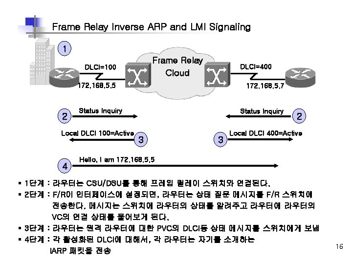

Stages of Inverse ARP and LMI Operation DLCI=100 Frame Relay Cloud 172. 168. 5. 5 DLCI=400 172. 168. 5. 7 Frame Relay Map 172. 168. 5. 5 Hello, I am 172. 168. 5. 7 5 6 7 DLCI 400 Active 5 4 Frame Relay Map 172. 168. 5. 7 DLCI 100 Active Hello, I am 172. 168. 5. 5 Keepalives 7 § 5단계 : 라우터가 IARP 메시지를 수신할 때, 로컬 DLCI와 원격지 IP로 맵 테이블을 만든다. § 6단계 : 매 60초마다 라우터는 모든 활성화된 DLCI를 역 ARPA 메시지에 전송한다. § 7단계 : 매 10초마다 라우터는 스위치와 LMI 정보를 교환한다. (Keepalive) 17 라우터는 F/R 스위치의 응답에 기초해서 각 DLCI 상태를 바꾼다.

* How Service Providers Map Frame Relay Dl. CIs How Service Providers Map Frame Relay DLCIs : Service Provider Network Sydney SYD 9. 4. 7=KYO 5. 3. 2 TOK 1. 3. 4=MEL 1. 2. 9 Branch Tokyo MEL 1. 2. 9=TOK 1. 3. 4 Melbourne KYO 5. 3. 2=SYD 9. 4. 7 Kyoto § 스위치는 inbound DLCI 값을 확인한다. § 스위치는 로컬 DLCI 값과 대비되는 원격지 DLCI의 값을 확인한다. § 스위치는 이두 DLCI 값을 F/R header에 포함해서, 적당한 switch. slot. port로 프레임을 전송한다. 18

How Service Providers Map Frame Relay DLCIs : Enterprise Sydney DLCI 112 Service Provider Network DLCI 411 Branch Tokyo DLCI 114 Melbourne DLCI 211 Kyoto § 위 그림은 원격 라우터에 일치하는 DLCI 값을 얻기 위해 역DLCI 값을 사용하는 것을 보여 준다. § Melbourne은 단순하게 DLCI 411을 사용하는 Tokyo로 부터 프레임이 도착 했다는 것을 알 수 있다. 19

Service Provider Frame Relay-to-ATM Interworking DLCI VPI/NCI DLCI 192 0/96 107 FRF. 5 Internetworking Function ATM PVC FRF. 5 Internetworking Function ATM Network DLCI = 192 DLCI = 107 Frame Relay PVC Frame Relay End Station § Frame Relay-to-ATM은 Frame Relay 와 ATM네트워크의 연속성을 제공한다. § 현재의 Frame Relay 사용자를 위해 명시적으로 개발된 두 이행 동의는 Network Interworking (FRF. 5)과 Service Interworking이다. (FRF. 8). § FRF. 5는 Frame Relay가 FRF. 5를 지원하는 중간의 ATM 네트워크 위로 통신하는 사용자를 허락하는 네트워크 interworking 기능성을 제공한다. § Multiprotocol 캡슐로 봉하기와 다른 higher-layer 과정은 ATM 네트워크 위로 투명하게 20 수송된다.

FRF. 8 Service Interworking Frame Relay End Station Frame Relay PVC FRF. 8 Internetworking Function ATM PVC ATM End Station § FRF. 8 은 Frame Relay 사용자와 ATM 사용자 사이의 통신을 허용한다. § FRF 8 은 서로 다른 Frame Relay와 ATM 설비 사이에 전송되는 트래픽의 변환을 담당한다. § Frame Relay-to-ATM을 설정할 때에는 인터페이스에 Frame Relay로 설정한다. 21

* Configuring a Basic Frame Relay Network Configuring Basic Frame Relay Cisco IOS Release 12. 0 Router HQ Interface serial 1 ip address 10. 16. 0. 1 255. 0 encapsulation frame-relay bandwidth 64 frame-relay lmi-type ansi Cisco IOS Release Prior to 11. 2 Branch Interface serial 1 ip address 10. 16. 0. 2 255. 0 encapsulation frame-relay bandwidth 64 frame-relay lmi-type ansi 23
 Step Action Notes 1단계 인터페이스를 선택하고, 설정모드로 들어간다.")
Configuring Basic Frame Relay (cont. ) Step Action Notes 1단계 인터페이스를 선택하고, 설정모드로 들어간다. Router(config)#interface serial 1 Router(config-if) 2단계 IP 주소와 같은 네트워크 주소를 설정한다. Router(config-if)#ip address 10. 16. 0. 1 255. 0 3단계 F/R 캡슐화 타입을 선택한다. Router(config-if)#encapsulation Frame-relay [ cisco |ietf ] Cisco : 다른 시스코 장비와 연결할 때 사용. Default ietf : 다른 라우터와 연결, IETF표준이다. 4단계 F/R LMI 타입을 선택한다. Router(config-if)#frame-relay lmi-type { ansi | cisco | q 933 a } Default LMI : cisco IOS 11. 2 이후버전에서는 자동감지 된다. 5단계 링크 대역폭 설정 Router(config-if)#bandwidth kilobits Bandwidth는 IGRP, EIGRP, OSPF 라우팅에 영향을 줌 6단계 Inverse ARP를 enable 시킨다. Router(config-if)#frame-relay inverse-arp [ protocol ] [ dlci ] Protocol : IP, IPX, Appletalk, DECnet DLCI 값 : 16 ~ 1007 24

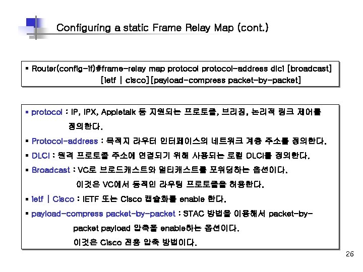
* Configuring a Static Frame Relay Map Configuring a static Frame Relay Map DLCI=110 IP Address=10. 16. 0. 1/24 HQ Branch DLCI=100 IP Address=10. 16. 0. 2/24 Interface serial 1 ip address 10. 16. 0. 1 255. 0 encapsulation frame-relay bandwidth 64 frame-relay map ip 10. 16. 0. 2 110 broadcast 25
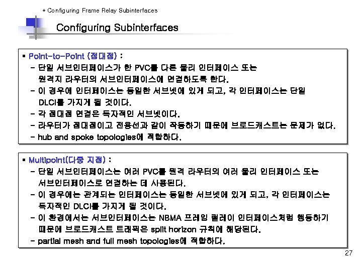

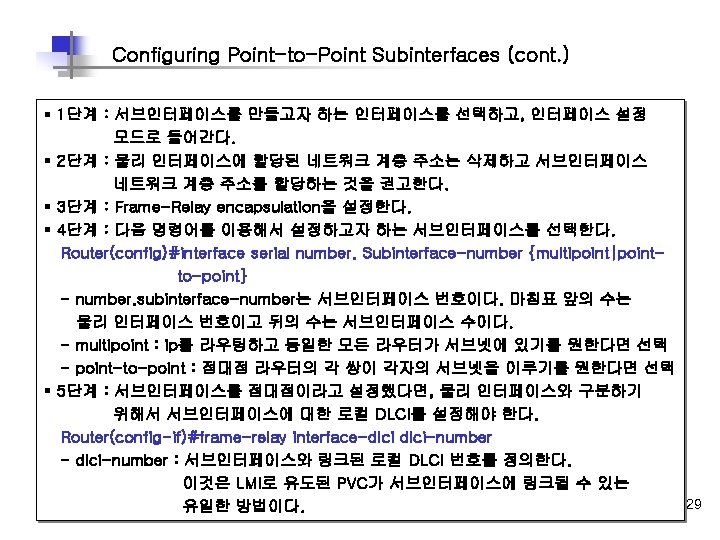
Configuring Point-to-Point Subinterfaces 10. 17. 0. 1 s 0. 2 A DLCI=110 10. 17. 0. 2 DL s 0. 3 C 10. 18. 0. 1 I=1 B 20 interface Serial 0 no ip address encapsulation frame-relay ! interface Serial 0. 2 point-to-point ip address 10. 17. 0. 1 255. 0 bandwidth 64 frame-relay interface-dlci 110 ! interface Serial 0. 3 point-to-point ip address 10. 18. 0. 1 255. 0 bandwidth 64 frame-relay interface-dlci 120 10. 18. 0. 2 C § 각각의 Subinterface에 대하여 해당 dlci값을 반드시 할당한다. § 각각의 point-to-point connection은 각각의 subnet을 필요로 한다. § 각 서브인터페이스는 독립된 물리 인터페이스처럼 처리되어 split horizon에 영향을 받지 않는다. 28

Multipoint Subinterface Configuration Example s 2. 2=10. 17. 0. 1/24 20 1 DLCI=130 RTR 1 DLCI= 140 interface Serial 2 no ip address encapsulation frame-relay ! interface Serial 2. 2 multipoint ip address 10. 17. 0. 1 255. 0 bandwidth 64 frame-relay map ip 10. 17. 0. 2 120 broadcast frame-relay map ip 10. 17. 0. 3 130 broadcast frame-relay map ip 10. 17. 0. 4 140 broadcast B s 2. 1=10. 17. 0. 2/24 RTR 3 s 2. 1=10. 17. 0. 3/24 RTR 4 s 2. 1=10. 17. 0. 4/24 § 하나의 Multipoint Subinterface를사용하므로 IP Address와 DLCI Map을 설정해 준다. § 하나의 subnet을 필요로 한다. NBMA이고 split-horizon 작동에 영향을 받을 수 있다. § Split-horizon은 기본적으로 F/R multipoint main interface에서는 disabled 되고 subinterface에서는 enable 된다. 30

* Verifying Basic Frame Relay Operations Verifying Frame Realy Operation Router#show frame-relay traffic § Frame-relay traffic 상태를 보여준다. Router#clear frame-relay-inarp § inverse arp를 사용하여 동적으로 생성된, Frame-relay 맵을 초기화 한다. Router#show interface type number § Frame-relay DLCI와 LMI 정보를 보여준다. Router#show frame-relay lmi [type number] § Frame-relay LMI 상태를 보여준다. Router#show frame-relay map § Frame-relay map 테이블을 보여준다. Router#show frame-relay PVC [ type number] § Frame-relay PVC 상태를 보여준다. 31

Show interfaces Example Router#show interface serial 0 Serial 0 is up, line protocol is up Hardware is CD 2430 in sync mode MTU 1500 bytes, BW 128 Kbit, DLY 20000 usec, rely 255/255, load 1/255 Encapsulation FRAME-RELAY, loopback not set, keepalive set (10 sec) LMI enq sent 112971, LMI stat recvd 112971, LMI upd recvd 0, DTE LMI up LMI enq recvd 0, LMI stat sent 0, LMI upd sent 0 LMI DLCI 1023 LMI type is CISCO frame relay DTE FR SVC disabled, LAPF state down Broadcast queue 0/64, broadcasts sent/dropped 32776/0, interface broadcasts 14 Last input 00: 00, output 00: 03, output hang never Last clearing of "show interface" counters never Input queue: 0/75/0 (size/max/drops); Total output drops: 0 Queueing strategy: weighted fair <Output Omitted> § Show interface 명령어는 Layer 1, 2의 상태에 관한 정보를 보여준다. § 또한 LMI type, LMI DLCI, DTE/DCE type, 등을 보여준다. § Cisco Router는 Frame relay switch로 사용 가능하다. 이러한 경우에는 DCE가 된다. ( 뒷면 LAB Test (1) 참조) 32

Show frame-relay lmi Example Router#show frame-relay lmi LMI Statistics for interface Serial 0 (Frame Relay DTE) LMI TYPE = CISCO Invalid Unnumbered info 0 Invalid Prot Disc 0 Invalid dummy Call Ref 0 Invalid Msg Type 0 Invalid Status Message 0 Invalid Lock Shift 0 Invalid Information ID 0 Invalid Report IE Len 0 Invalid Report Request 0 Invalid Keep IE Len 0 Num Status Enq. Sent 113100 Num Status msgs Rcvd 113100 Num Update Status Rcvd 0 Num Status Timeouts 0 § show frame-relay lmi 명령어는 LMI 트래픽 통계를 보여준다. § 로컬 라우터와 프레임 릴레이 스위치간에 교환되는 상태 메시지의 개수를 보여준다. 33

Show frame-relay PVC Example Router# show frame-relay pvc 100 PVC Statistics for interface Serial 0 (Frame Relay DTE) DLCI = 100, DLCI USAGE = LOCAL, PVC STATUS = ACTIVE, INTERFACE = Serial 0 input pkts 14055 output pkts 32795 in bytes 1096228 out bytes 6216155 dropped pkts 0 in FECN pkts 0 in BECN pkts 0 out FECN pkts 0 out BECN pkts 0 in DE pkts 0 out bcast pkts 32795 out bcast bytes 6216155 PVC create time 00; 03; 46 last time PVC status changed 00; 03; 47 § Frame Relay operation과 Remote Router와의 연결 상태를 보여준다. § PVC traffic 통계를 보여준다. § 라우터에 수신된 BECN, FECN 패킷을 보는 데에도 유용하다. Ø PVC Status • Active state : 라우터간에 정보를 교환할 수 있는 정상적인 상태이다. • Inactive state : Local 라우터에서 스위치 오피스까지 에는 이상이 없으나 Remote 라우터가 응답이 없는 상태이다. • Deleted state : Local Router와 스위치간에 LMI Information이 없는 경우이다. 34
: ip 10. 140.")
Show frame-relay map Example Router# show frame-relay map Serial 0 (up): ip 10. 140. 2. 1 dlci 100(0 x 64, 0 x 1840), dynamic, broadcast, , status defined, active § show frame-relay map은 연결에 대한 현재의 map 엔트리와 정보를 보여준다. § 역 ARP 엔트리를 학습했는지 뿐만 아니라 설정된 정적 맵 엔트리를 보여준다. - 100 : 10진수의 DLCI 번호이다. - 0 x 64 : 16진수 표현이다. (0 x 64 = 십진수 100) - 0 x 1840 : Frame relay address field에 나타나는 DLCI 값 - 10. 140. 1. 1 : 원격 라우터 IP 주소(IARP에 의해 동적으로 배운 주소이다. ) - Broadcast/multicast는 PVC 상에서 enabled 되어 있다. - PVC 상태는 active 이다. Router# sh frame map Serial 0 (up): ip 10. 140. 2. 1 dlci 100(0 x 64, 0 x 1840), dynamic, broadcast, , status defined, active Router#clear frame-relay-inarp : 동적으로 생성된 F/R 맵을 초기화 한다. Router#sh frame map Router# 35

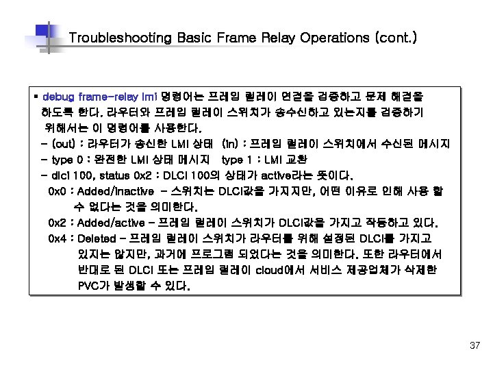
Troubleshooting Basic Frame Relay Operations Router#debug frame-relay lmi Frame Relay LMI debugging is on Displaying all Frame Relay LMI data Router# 1 w 2 d: Serial 0(out) : St. Eng, myseq 140, yourseen 139, DTE UP 1 w 2 d: datagramstart = 0 x. E 008 EC, datagramsize = 13 1 w 2 d: FR encap = 0 x. FCF 10309 1 w 2 d: 00 75 01 01 01 03 02 8 C 8 B 1 w 2 d: Serial 0(in): Status, myseq 140 1 w 2 d: RT IE 1, length 1, type 1 1 w 2 d: KA IE 3, length 2, yourseq 140, mseq 140 1 w 2 d: Serial 0(out) : St. Eng, myseq 141, yourseen 140, DTE UP 1 w 2 d: datagramstart = 0 x. E 008 EC, datagramsize = 13 1 w 2 d: FR encap = 0 x. FCF 10309 1 w 2 d: 00 75 01 01 01 03 02 8 D 8 C 1 w 2 d: Serial 0(in): Status, myseq 142 1 w 2 d: RT IE 1, length 1, type 0 1 w 2 d: KA IE 3, length 2, yourseq 142, mseq 142 1 w 2 d: PVC IE 0 x 7, length 0 x 6, dlci 100, status 0 x 2, bw 0 36
 v Frame Relay Switch Configuration Example E 0: 172. 16. 1.")
LAB Test (1) v Frame Relay Switch Configuration Example E 0: 172. 16. 1. 1 S 0: 10. 1. 1. 1 172. 16. 1. 21 Router_A DLCI 16 S 0: 10. 1. 1. 2 S 0 E 0: 192. 168. 1. 1 S 1 Router_C DLCI 33 192. 168. 1. 2 FR(config)# frame-relay switching FR(config)# interface Serial 0 FR(config-if)# no ip address FR(config-if)# encapsulation frame-relay FR(config-if)# clockrate 64000 FR(config-if)# frame-relay intf-type dce FR(config-if)# frame-relay route 16 interface Serial 1 33 FR(config-if)# FR(config-if)# interface Serial 1 no ip address encapsulation frame-relay clockrate 64000 frame-relay intf-type dce frame-relay route 33 interface Serial 0 16 38
 v Frame-relay Point-to-point LAB E 0: 172. 16. 1. 1 172.")
LAB Test (2) v Frame-relay Point-to-point LAB E 0: 172. 16. 1. 1 172. 16. 1. 21 E 0: 192. 168. 1. 1 S 0: 10. 1. 1. 1 Router_A S 0: 10. 1. 1. 2 DLCI 16 Router_C 192. 168. 1. 21 DLCI 33 Router_A(config)# interface Serial 0 Router_A(config-if)# no ip address Router_A(config-if)# encapsulation frame-relay Router_A(config-if)# interface Serial 0. 1 point-to-point Router_A(config-subif)# ip address 10. 1. 1. 1 255. 0 Router_A(config-subif)# frame-relay interface-dlci 16 Router_C(config)# interface Serial 0 Router_C(config-if)# ip address 10. 1. 1. 2 255. 0 Router_C(config-if)# encapsulation frame-relay Router_C(config-if)# frame-relay interface-dlci 33 39
 v Frame-relay Multipoint LAB E 0: 172. 16. 1. 1 172.")
LAB Test (3) v Frame-relay Multipoint LAB E 0: 172. 16. 1. 1 172. 16. 1. 21 S 0: 10. 1. 1. 1 E 0: 192. 168. 1. 1 S 0: 10. 1. 1. 2 Router_C Router_A DLCI 16 DLCI 33 192. 168. 1. 21 Router_A(config)# interface Serial 0 Router_A(config-if)# no ip address Router_A(config-if)# encapsulation frame-relay Router_A(config-if)# interface Serial 0. 2 multipoint Router_A(config-subif)# ip address 10. 1. 1. 1 255. 0 Router_A(config-subif)# frame-relay map ip 10. 1. 1. 2 16 broadcast Router_C(config)# interface Serial 0 Router_C(config-if)# no ip address Router_C(config-if)# encapsulation frame-relay Router_C(config-if)# interface Serial 0. 2 multipoint ip address 10. 1. 1. 2 255. 0 encapsulation frame-relay 40 frame-relay map ip 10. 1. 1. 1 33 broadcast
 v 확인 명령어 § show running-config - 현재 설정상태를 보여준다. §")
LAB Test (4) v 확인 명령어 § show running-config - 현재 설정상태를 보여준다. § show interface serial 0. 1 - 서브인터페이스의 상태를 보여준다. § show frame-relay pvc 16 - DLCI 16에 대한 PVC 값을 보여준다. § show frame-relay lmi - LMI 상태를 보여준다. § show frame-relay traffic - traffic 상태를 보여준다. § show frame-relay map - F/R 맵핑 상태를 보여준다. § debug frame-relay lmi - F/R의 연결을 검증하고 문제해결에 도움을 준다. 41
- Slides: 41