CHAPTER 1 REVIEW OF BASIC POWER SYSTEM PRINCIPLE

CHAPTER 1: REVIEW OF BASIC POWER SYSTEM PRINCIPLE AND CALCULATION PER- UNIT AND SINGLE LINE DIAGRAM

Per-Unit Method • The per-unit system is a widely system of normalization. Being familiar with it is essential to functioning in the world of electric power engineering. • What is per-unit o The per-unit system is a way to transform the numerical quantities (voltages, currents, powers, and impedances) to gain certain advantages while maintaining the basic relations between them (Ohm’s laws). o The per unit system is very similar to the percent system, except that when percentage quantities are to be multiplied or divided additional factors of 100 must be brought in which are not in the original equations. 2

Per-Unit Method • Some Of Advantages Of Per-unit System o It gives a clear idea of relative magnitudes of various quantities such as voltage, current, power and impedance. o The per unit impedance of equipment of the same general type based on their own rating of the equipment. Whereas their impedance in ohms vary greatly with the rating. o The factors of √ 3 and 3 are eliminated in the per unit system thus the circuit laws are valid in per unit systems. 3

Per-Unit Method • Some Of Advantages Of Per-unit System o The per unit value of impedance, voltage and current of a transformer are the same regardless of whether they are referred to the primary or the secondary side. This is greatly advantage since the different voltage level disappear and the entire system reduces to a system of simple impedance. o The per unit systems are ideal for the computerized analysis and simulation of complex power system problem. 4

Per-Unit Method • The basic per-unit scaling equation is • S, V , I and Z are expressed as a fraction of the actual or base value 5

Per-Unit Method • Calculation for Single Phase Systems o If SB and VB are the selected base quantities of power (complex, active or reactive) and voltage, then o Base current o Base Impedance 6

Per-Unit Method • Calculation for Single Phase Systems o Voltages and power are usually expressed in k. V and MVA, thus it is usual to select a MVAB and k. VB and to express o Base current in k. A o Base Impedance in Ω • In these expressions, all the quantities are single phase quantities. 7

Per-Unit Method • Calculation for Single Phase Systems o The extension to other related variables is routine. For example, o In case of impedance, 8

Per-Unit Method • Calculations for Three Phase Systems o In three phase systems the line voltage and the total power are more important than the per phase quantities. It is thus usual to express base quantities in terms of these. o If S 3φB and VLLB are three phase base power and line to line voltage respectively, o Base current o Base Impedance 9

Per-Unit Method • Calculations for Three Phase Systems o In terms of MVA 3φB and k. VLLB o Base current in k. A o Base Impedance in Ω 10

Per-Unit Method • Calculations for Three Phase Systems o Thus in three phase, the calculations of per unit quantities becomes 11

Per-Unit Method • Calculations for Three Phase Systems o P and Q have the same base as S, so that o Similarly, R and X have the same base as Z, so that o The power factor remains unchanged in per unit. 12
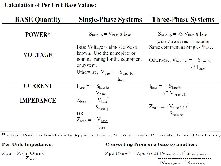

Per-Unit Method • Conversions From One Base To Another o It is usual to give data in per unit to its own rating. o As different components can have different ratings, it is necessary to convert all quantities to a common base to do arithmetic operations. o Additions, subtractions, multiplications and divisions will give meaningful results only if they are to the same base. This can be done for three phase systems as follows. 14

Per-Unit Method • Conversions From One Base To Another o The conversion from one base to another can be done for three phase systems as follows * LLB : line to line base 15

Per-Unit Method • Per Unit Quantities Across Transformer o Although the power rating on either side of a transformer remains the same, the voltage rating changes, and so does the base voltage across a transformer o This is like saying that full or 100% (or 1 pu) voltage on the primary of a 220/33 k. V transformer corresponds to 220 k. V while on the secondary it corresponds to 33 k. V. 16

Per-Unit Method • Per Unit Quantities Across Transformer o While a common S 3φB can be selected for a power system, a common VLLB must be chosen corresponding to a particular location and changes in proportion to the nominal voltage ratio whenever a transformer is encountered. o Assuming Ideal transformer, a is define as turns ratio o The current base changes inversely as the ratio. 17

Per-Unit Method • Per Unit Quantities Across Transformer • For a transformer with turns ratio NP: NS, base quantities change as follows. Primary Base Secondary Base Power (S, P and Q) SB SB Voltage (V) V 1 B∙(NS/NP)=V 2 B Current (I) SB/√ 3 V 1 B∙(NP/NS)=SB/√ 3 V 2 B V 1 B 2/SB∙(NS/NP)2=V 2 B 2/SB Quantity Impedance (Z, R and X) 18

Per-Unit Method • Draw a Single Line Diagram for the power system (Generators, Motors, Transformers & Lines). o 1. Identify the Appropriate Symbols Common power symbols used in single line diagrams 19

Three-phase power system represented by single line diagram

o identify the grounding connection, or whether the device is wye- or deltaconnected. Identification for wye-connected generator or motor. (a) Solidly grounded. (b) Grounded through an inductance. (c) The transformer is identified as being delta-wye, with the wye side solidly grounded.

Single line diagram of electric-power system supplying motor loads. Specifications are given in above table.
 Circuit with elements in SI")
Per-Unit Method : Example 1 • Figure 1 (a) Circuit with elements in SI units. • Figure 1 (b) Circuit with elements in per-unit. Figure 1 23
 Solve for Z, I, and S at")
Per-Unit Method : Example 1 • (a) Solve for Z, I, and S at Port ab in Figure 1 (a) • (b) Repeat (a) in per-unit on bases of VB=100 V and SB=1000 V. Draw the corresponding per unit circuit. 24
 Solution for Z, I, and S at Port")
Per-Unit Method: Example 1 Solution (a) Solution for Z, I, and S at Port ab in Figure 1 (a) 25
 Answer in per-unit on bases of VB=100 V")
Per-Unit Method: Example 1 Solution (b) Answer in per-unit on bases of VB=100 V and SB=1000 V 26
 Answer in per-unit on bases of VB=100")
Per-Unit Method : Example 1 Solution (b) Answer in per-unit on bases of VB=100 V and SB=1000 V 27
 Converting result in (b) into SI unit")
Per-Unit Method: Example 1 Solution • (b) Converting result in (b) into SI unit • It shows that the results of (a) and (b) are identical. 28

Per-Unit Method: Example 2 • A 200 MVA, 13. 8 k. V generator has a reactance of 0. 85 pu and is generating 1. 15 pu voltage. • Determine: - (a) the actual values of the line voltage, phase voltage and reactance, and (b) the corresponding quantities to a new base of 500 MVA, 13. 5 k. V. 29
 Line voltage Phase voltage Reactance = pu voltage")
Per-Unit Method: Example 2 Solution (a) Line voltage Phase voltage Reactance = pu voltage x Base line voltage = 1. 15 x 13. 8 k. V = 15. 87 k. V = pu voltage x Base phase voltage =1. 15 x(13. 8 k. V/√ 3) = 9. 16 k. V = pu reactance x( Base line voltage 2/ MVA) =0. 85 x ( 13. 8 k. V 2/200 MVA ) = 0. 809 Ω 30
 Line voltage pu (2) Phase voltage pu")
Per-Unit Method : Example 2 Solution (b) Line voltage pu (2) Phase voltage pu (2) Reactance pu (2) = Vpu. LL(1) x (VBLL(1) / VBLL(2)) = 1. 15 x (13. 8 k. V /13. 5 k. V) = 1. 176 pu = Vpu. LL(1) x (VBφ(1) / VBφ(2)) =1. 15 x (13. 8 k. V /√ 3) / (13. 5 k. V/√ 3) = 1. 176 pu = Xpu(1) x (VLLB(1)/VLLB(2))2 x(SB(2)/SB(1)) =0. 85 x (13. 8 k. V/13. 5 k. V)2(500 MVA/200 MVA) = 2. 22 pu 31

Per-Unit Method : Example 3 • Draw an impedance in per unit diagram for the system whose one-line diagram is shown in Figure below: 32

Per-Unit Method : Example 3 Data for the system is: o o o o o G 1: 50 MVA, 13. 8 k. V, X=0. 15 pu G 2: 20 MVA, 14. 4 k. V, X=0. 15 pu M : 20 MVA, 14. 4 k. V, X=0. 15 pu T 1 : 60 MVA, 13. 2 k. V/161 k. V, X=0. 10 pu T 2 : 25 MVA, 13. 1 k. V/161 k. V, X=0. 10 pu T 3 : 25 MVA, 13. 2 k. V/160 k. V, X=0. 10 pu (I changed voltage rating on LV side of T 2 and HV side of T 3) Line 1: 20+j 80 ohms Line 2: 10+j 40 ohms Line 3: 10+j 40 ohms Load: 20+j 15 MVA at 12. 63 k. V 33

Per-Unit Method : Example 3 Solution • We begin by choosing the system power base as S 3φB=100 MVA. • We must also choose the voltage base in one section of the system. We will select 161 k. V in Section D. • Now we compute the voltage bases in the other three sections of the system. o Section A: o Section B: o Section C: 34

Per-Unit Method : Example 3 Solution • Next convert the given per-unit impedances for G 1, G 2, M, T 1, T 2, and T 3 into per-unit impedances on new bases. • G 1: • G 2: • M: 35

Per-Unit Method : Example 3 Solution • Next convert the given per-unit impedances for G 1, G 2, M, T 1, T 2, and T 3 into per-unit impedances on new bases. • T 1: • T 2: • T 3: 36

Per-Unit Method : Example 3 Solution • Note that the last calculation (for T 3) could have been done as follows: • T 3: • Next, let’s per-unitize the lines. The line impedances are all in ohms, we need to find the impedance base for Section D 37

Per-Unit Method : Example 3 Solution Then, per-unitize the lines L 1, L 2 and L 3 38

Per-Unit Method • Finally, we need to compute the load, assume it use a series combination. • Next, compute ZB at section C, 39

Per-Unit Method • Compute the per unit impedance as • Per-Unit impedance diagram 40

General Layout of the System 41

General Layout of the System • One/Single line diagram 42

General Layout of the System Large Generation Stations Overview Of The Electricity Infrastructure Bulk Transmission 230 -750 k. V Sub transmission 69 -169 k. V Primary Distribution 4 -36 k. V Secondary Distribution 120/240/415 V 43

Example 5 • Determine the new normalized per unit impedance for the system if the system wide base, Sbase of 100 MVA

Solution: Example 5 • Resistive impedance for most components have been ignored • Capacitive effects between lines-ground are being neglected • Rotating machines have been replaced with a voltage source behind their internal reactance

Solution: Example 5 • Step 1: Identify the voltage base The system base, S base = 100 MVA, The voltage base is determined by the transformer

Solution: Example 5 • Step 2: Calculate the base impedance For T-line 1, T-line 2 and 3 -phase load • Step 4: Calculate the per unit impedance For T-line 1, T-line 2, 3 -phase load, Xgen, XT 1 (new), XT 2 new, XT 3 new

END OF CHAPTER 1
- Slides: 48