Chapter 1 Introduction to Microprocessor and the Computer


 • TPA holds the DOS (Disk Operating System) and other")


 Base 2:")


of a 10111000, add the")


 Data • BCD information is stored in either packed or")


- Slides: 38
Chapter 1 Introduction to Microprocessor and the Computer Asst. Prof. Dr. Gazi Erkan BOSTANCI Slides are mainly based on The Intel Microprocessors by Barry B. Brey, 2008
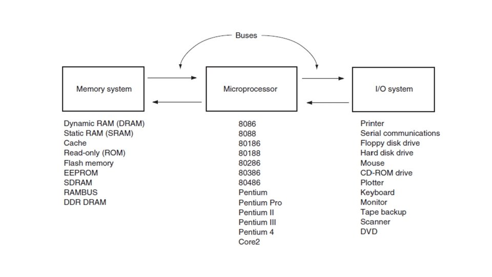
The Microprocessor based Computer System • Computer systems have undergone many changes recently. Machines that once filled large areas have been reduced to small desktop computer system because of the microprocessor. • Here we are going to examine the structure of the MP-based personal computer system.
• Above is the diagram of the personal computer. There are three blocks connected by buses. A bus is a set of common connections that carry the same type of information. • For instance, the address bus constains 20 or more connections, conveys the memory address to the memory.
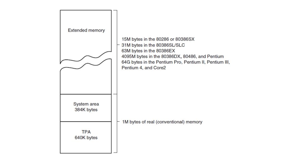
The Memory and the I/O System • The memory system is divided into three main parts. • TPA (Transient Program Area) • System Area • XMS (Extended Memory System)
TPA (Transient Program Area) • TPA holds the DOS (Disk Operating System) and other programs that control the computer system. This is a DOS concept not really applicable to Windows. • TPA also stores active and inactive DOS application programs.
• Note the hexadecimal memory address or memory locations. These are used to number each byte of the memory system. • 1234 H or 0 x 1234 • The interrupt vectors access various features of DOS, BIOS and applications. • The IO. SYS is the program that allows DOS to use the keyboard, video display, printers. • Drivers are programs that control installable I/O devices such as mouse, disk or CDROM. • Command. com controls the operation of the computer from the keyboard when operated in DOS mode. • Never erase the command. com, IO. sys or msdos. sys to make room for other software or your computer will not function.
The System Area • The system area contains programs on either a read only memory (ROM) or flash memory and arease of read/write (RAM) memory for data storage. • The first area of the system space contains video display RAM and video control programs on ROM or flash memory. This area starts at location A 0000 H and extends to location C 7 FFFH. • The size and amount of memory used depends on the type of video display adapter attached to the system.
• The area at locations C 8000 H–DFFFFH is often open or free. This area is used for the expanded memory system (EMS) in a PC. • Memory locations E 0000 H–EFFFFH contain the cassette BASIC language on ROM found in early IBM personal computer systems. This area is often open or free in newer computer systems. • Finally, the system BIOS ROM is located in the top 64 K bytes of the system area (F 0000 H–FFFFFH). This ROM controls the operation of the basic I/O devices connected to the computer system. It does not control the operation of the video system, which has its own BIOS ROM at location C 0000 H. The first part of the system BIOS (F 0000 H–F 7 FFFH) often contains programs that set up the computer; the second part contains procedures that control the basic I/O system.
Windows Systems • Note that the Tpa starts with memory address 0000 H does not mean that any program written for Windows will begin at this physical address. • The processes use page tables. The tables define where in the physical memory each 4 K-byte page of the process is located. • In this way, applications can use up to 2 Gbyte memory even the computer has less memory. • The system (OS) uses the harddisk drive in case the physical memory is not sufficent. (Virtual memory)
I/O Space • The I/O space extends from I/O port 0000 H to port FFFFH. An I/O port address is similar to a memory address, but instead of addressing memory, it addresses an I/O device. • You can check the Device Manager to see the list of I/O devices connected to your computer.
• Many I/O devices are not directly addressed. Instead, the system BIOS ROM addresses these basic devices which can vary in location and function from one computer to another. • Access to most I/O devices should always be made through Windows, DOS or BIOS function calls to maintain compatibility from one computer system to another.
The Microprocessor • The MP is the controlling element in a computer system. It is also referred to as CPU (Central Processing Unit). It controls memory and I/O through a series of connections called buses. • The buses select an I/O or memory device, transfer data between the I/O device or memory and the MP control the I/O and memory system. • Memory and I/O are controlled through instructions that are stored in the memory and executed by the MP.
• The MP performs three main tasks: 1. Data transfer between itself and the memory or I/O system. 2. Simple arithmetic and logic instructions 3. Program flow via simple decisions. • The power of MP is its capability to execute billions of millions (MIPS, FLOPS) of instructions per second from a program (software, a group of instructions) stored in the memory system.
Arithmetic and Logic Operations • These operations are very basic but using them, very complex problems are solved. Data are operated upon from the memory system or internal registers. • Addition, subtraction, multiplication, division, AND, OR, NOT, NEG, shift, rotate • Data widths may vary: • Byte: 8 bits • Word: 16 bits • Double Word: 32 bits
Decisions • Simple decisions are used to control the program flow which allows making decisions through numeric facts. • • • Zero (Test a number for zero or not zero) Sign (Test a number for positive or negative) Carry (Test for carry after addition or borrow after subtraction) Parity (Test a number for an even or odd number of ones) Overflow (Test for overflow which indicates an invalid result after signed addition or subtraction)
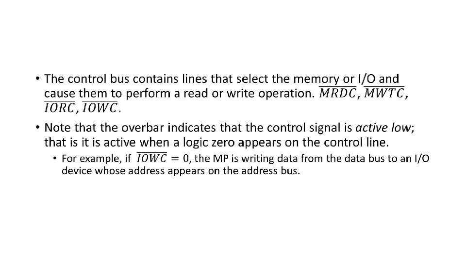
Buses • A bus is a common group of wires that interconnect components in a computer system. They transfer address, data or control information between the MP and its memory and I/O systems.
• When addressing I/O, the 16 bit I/O address can select one of the 64 I/O devices from 0000 H to FFFFH. • On the other hand, when addressing memory, 20 bit addresses are used from 00000 F to FFFFFH in order to address 1 Mbyte of memory. • The data bus transfers information between MP and its memory and I/O system. Data transfer vary in size from 8 bits wide to 64 bits wide. 8086 can transfer 16 bits of data through their buses, Core 2 can transfer 64 bits.
Number Systems • Digits: • • Base 10 : 0 -9 (decimal) Base 2: 0 -1 (binary) Base 8: 0 -7 (octal) Base 16: 0 -15 (hexadecimal) A=10, B=11, C=12, D=13, E=14, F=15 • Positional Notation • Positions to the left of the radix (number base) point -> positive power • Positions to the rightof the radix (number base) point -> negative power
• Ex 1. Conversion from binary to decimal • Ex 2. Conversion from base 6 to decimal
• Ex 3. Conversion from hexadecimal to decimal • Ex 4. Conversion from decimal (whole number)
• Ex 5. Conversion from decimal to octal • Ex 6. Conversion from decimal to hexadecimal
Converting from a decimal fraction • Algorithm 1. Multiply the decimal fraction by the radix (base). 2. Save the whole number portion of the result as a digit (event it is a zero). Note that the first result is immediately to the right of the radix point. 3. Repeat steps 1 and 2, us, ing the fractional part of step 2 until the fractional part of step 2 is zero.
• Ex 7. Conversion to binary 0. 125 = X 2 0. 125 * 2 = 0. 25 digit is 0 0. 25 * 2 = 0. 5 digit is 0 0. 5 * 2 = 1. 0 digit is 1 Result is 0. 0012 • Ex 8. Conversion to octal 0. 125 = X 8 0. 125 * 8 = 1. 0 digit is 1 Result is 0. 18 • Ex 8. Conversion to hexadecimal 0. 46875 = X 16 0. 46875 * 16 = 0. 75 digit is 0 0. 75 * 16 = 12. 0 digit is C Result is 0. 0 C 16
Binary Coded Hexadecimal • BCH is used to represent hexadecimal data in binary code. • Ex 10. 2 AC = 0010 1100 • Ex 11. 1000 0011 1101. 1110 = 83 D. E
Complements • Sometimes data are stored in complement fomr to represent negative numbers. There are two systems to represent negative data: • Radix complement • Radix-1 complement • Ex 12. Represent 8 bit binary number 01001100 in one’s complement to show it as a negative value. 1 1 1 1 0 1 0 1 1 0 0 1 1
• Ex 13. 5 CD in radix-1 complement 15 15 15 5 C D A 3 2
• Radix-1 complement is not used by itself; it is used as a step for finding radix complement which is used to represent negative numbers in modern computer systems. • To find radix complement, first find radix-1 complement then add 1 to the result. • Note that the problem with radix-1 complement is that a negative or positive zero exists; in the radix complement system only a positive zero can exist.
• Ex 14. 1 1 1 1 0 1 0 0 0 1 1’s complement 1 1 0 1 1 1 0 0 0 2’s complement • Ex 15. 15 15 15 3 4 5 C B A 1 C B B 15’s complement 16’s complement
• To prove that 01001000 is the inverse (negative)of a 10111000, add the two together to form an 8 -digit result. The ninth digit is dropped and the result is zero.
Computer Data Formats • Successful programming requires precise understanding of data formats.
ASCII and Unicode Data • 7 bit code with the eight and most significant bit used to hold parity (in old systems). • If used with a printer, most significant 0 for alphanumeric printing, 1 for graphics printing. • Since Windows, Unicode is used to store alphanumeric data (each character is 16 bit).
BCD (Binary Coded Decimal) Data • BCD information is stored in either packed or unpacked forms. Packed BCD data are stored as two digits per byte and unpacked BCD data are stored as one digit per byte. • The range of a BCD digit extends from 00002 to 10012 or 0 -9 for decimal. • Unpacked BCD data are returned from a keypad or keyboard. • Packed BCD data are used for some of the instructions included for BCD addition and subtraction in the instruction set of the MP.
Decimal Packed Unpacked 12 0001 0010 0001 0000 0010 623 0000 0110 0011 0000 0110 0000 0011 • Ex 16. ; Unpacked BCD data (least-significant data first) NUMB 1 DB 3, 4, 5 ; defines number 543 ; packed BCD NUMB 2 DB 3, 45 H; defines number 4503 ; DB is define bytes
• Byte sized data • Byte-sized data are stored as unsigned and signed integers. 128 64 32 16 8 4 2 1 Unsigned byte -128 64 32 16 Signed byte 8
• Whenever a number is two’s complement, its sign changes from negative to positive or positive to negative. +8 0 0 1 0 0 0 1 1 1 1’s complement 1 -8 1 1 1 0 0 0 2’s complement