Chapter 04 Digital Transmission ANALOGTODIGITAL CONVERSION A digital


 2. Delta Modulation")
 is")


 �PCM is a very complex technique. �Delta modulation techniques have been developed")
")


- Slides: 30
Chapter 04 Digital Transmission
ANALOG-TO-DIGITAL CONVERSION �A digital signal is superior to an analog signal because it is more robust to noise and can easily be recovered, corrected and amplified. �For this reason, the tendency today is to change an analog signal to digital data.
ANALOG-TO-DIGITAL CONVERSION �Two Techniques: 1. Pulse code modulation (PCM) 2. Delta Modulation
Pulse Code Modulation �Technique to change an analog signal to digital data (digitization) is called pulse code modulation (PCM).
Components of PMC encoder
Pulse Code Modulation �The analog signal is sampled. �The sampled signal is quantized. �The quantized values are encoded as streams of bits.
Sampling �The first step in PCM is sampling. �The analog signal is sampled every Ts s, where Ts is the sample interval or period. �The inverse of the sampling interval is called the sampling rate or sampling frequency and denoted by fs, where fs = I/Ts
Sampling �According to nyquist theorem, the sampling rate must be at least 2 times the highest frequency contained in the signal.
Sampling
Quantization Levels �The midpoint of each zone is assigned a value from 0 to L-1 (resulting in L values) �Each sample falling in a zone is then approximated to the value of the midpoint. 4. 10
Quantization �Sampling results in a series of pulses of varying amplitude values ranging between two limits: a min and a max. �The amplitude values are infinite between the two limits. �We need to map the infinite amplitude values onto a finite set of known values. �This is achieved by dividing the distance between min and max into L zones, each of height = (max - min)/L 4. 11
Quantization Zones �Assume we have a voltage signal with amplitudes Vmin=-20 V and Vmax=+20 V. �We want to use L=8 quantization levels. �Zone width = (20 - -20)/8 = 5 �The 8 zones are: -20 to -15, -15 to -10, -10 to -5, -5 to 0, 0 to +5, +5 to +10, +10 to +15, +15 to +20 �The midpoints are: -17. 5, -12. 5, -7. 5, -2. 5, 7. 5, 12. 5, 17. 5 4. 12
Assigning Codes to Zones �Each zone is then assigned a binary code. �The number of bits required to encode the zones, or the number of bits per sample as it is commonly referred to, is obtained as follows: nb = log 2 L �Given our example, nb = 3 �The 8 zone (or level) codes are therefore: 000, 001, 010, 011, 100, 101, 110, and 111 �Assigning codes to zones: � 000 will refer to zone -20 to -15 � 001 to zone -15 to -10, etc. 4. 13
Figure 4. 26 Quantization and encoding of a sampled signal 4. 14
Encoding �The last step in PCM is encoding. �After each sample is quantized and the number of �bits per sample is decided, each sample can be changed to an nb-bit code word. �the number of bits for each sample is determined from the number of quantization levels. �If the number of quantization levels is L, the number of bits is nb =log 2 L. Bit rate = sampling rate x number of bits per sample
Delta Modulation(DM) �PCM is a very complex technique. �Delta modulation techniques have been developed to reduce the complexity of PCM. �PCM finds the value of the signal amplitude for each sample. �DM finds the change from the previous sample. �Note that in figure there are no code words here; bits are sent one after another.
Delta Modulation(DM)
Delta Modulator
Delta Demodulator
TRANSMISSION MODES The transmission of binary data across a link can be accomplished in either parallel or serial mode. In parallel mode, multiple bits are sent with each clock tick. In serial mode, 1 bit is sent with each clock tick. While there is only one way to send parallel data, there are three subclasses of serial transmission: asynchronous, and isochronous. Parallel Transmission Serial Transmission 4. 20
Data transmission and modes 4. 21
Parallel transmission 4. 22
Serial transmission 4. 23
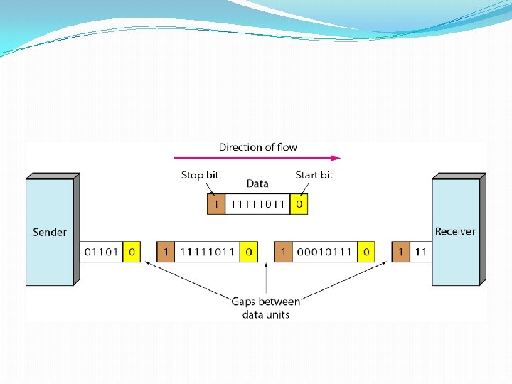
Asynchronous Transmission �Asynchronous transmission is so named because the timing of a signal is unimportant. �To alert the receiver to the arrival of a new group, 0 bit is added to the beginning of each byte, which is called the start bit. �To let the receiver know that the byte is finished, 1 or more additional bits are appended to the end of the byte. �These bits, usually 1 s, are called stop bits. �By this method, each byte is increased in size to at least 10 bits, of which 8 bits is information and 2 bits or more are signals to the receiver.
Asynchronous Transmission �But within each byte, the receiver must still be synchronized with the incoming bit stream. �That is, some synchronization is required, but only for the duration of a single byte. �The receiving device resynchronizes at the onset of each new byte. �When the receiver detects a start bit, it sets a timer and begins counting bits as they come in. �After n bits, the receiver looks for a stop bit. �As soon as it detects the stop bit, it waits until it detects the next start bit.
Asynchronous Advantages �It is cheap and effective for low-speed communication. �For example, the connection of a keyboard to a computer is a asynchronous transmission. �A user types only one character at a time, types extremely slowly in data processing terms, and leaves unpredictable gaps of time between each character.
Synchronous Transmission �In synchronous transmission, the bit stream is combined into longer "frames, " which may contain multiple bytes. �Each byte, however, is introduced onto the transmission link without a gap between it and the next one. �It is left to the receiver to separate the bit stream into bytes for decoding purposes. �In other words, data are transmitted as an unbroken string of 1 s and 0 s, and the receiver separates that string into the bytes, or characters, it needs to reconstruct the information. �Timing becomes very important because the accuracy of the received information is completely dependent on the ability of the receiving device to keep an accurate count of the bits as they come in. �The advantage of synchronous transmission is speed.
Synchronous Transmission
Synchronous Transmission