
Chandra Xray Observatory Overview Roger Brissenden Smithsonian Astrophysical
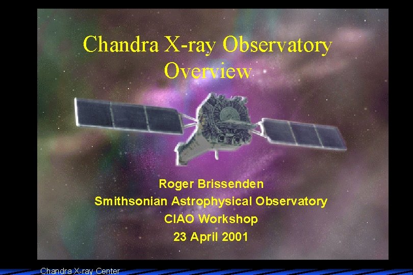
Chandra X-ray Observatory Overview Roger Brissenden Smithsonian Astrophysical Observatory CIAO Workshop 23 April 2001 Chandra X-ray Center
Overview 1. Mission Summary, Launch and Architecture 2. Mission and Observatory Description 3. Spacecraft Subsystems 4. High Resolution Mirror Assembly 5. Science Instruments 6. Chandra X-ray Center Architecture Chandra X-ray Center
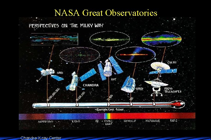
NASA Great Observatories CHANDRA Chandra X-ray Center
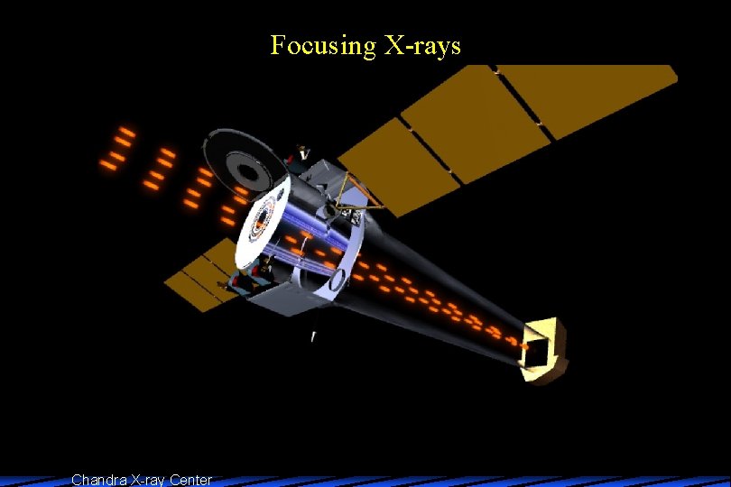
1. Chandra Mission Summary u Launch July 23, 1999 – STS-93/ Inertial Upper Stage / Integral Propulsion System – 10, 000 km x 140, 000 km, 28. 4 o Inclined Orbit u u Design Lifetime > 5 Years 10 -m Focal Length Wolter -1 Mirror: 4 nested Mirror Pairs Energy Range: 0. 1 -10 Ke. V 2 Imaging Focal Plane Science Instruments – ACIS (Advanced CCD Imaging Spectrometer) – HRC (High Resolution Camera) u 2 Objective Transmission Gratings for Dispersive Spectroscopy – LETG (Low-Energy Transmission Grating) – HETG (High-Energy Transmission Grating) Chandra X-ray Center
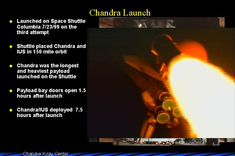
Chandra Launch u Launched on Space Shuttle Columbia 7/23/99 on the third attempt u Shuttle placed Chandra and IUS in 150 mile orbit u Chandra was the longest and heaviest payload launched on the Shuttle u Payload bay doors open 1. 5 hours after launch u Chandra/IUS deployed 7. 5 hours after launch Chandra X-ray Center
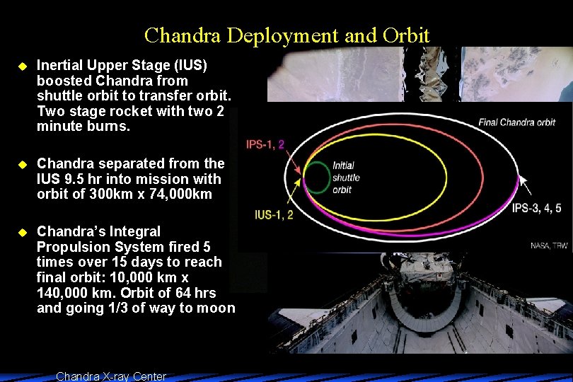
Chandra Deployment and Orbit u Inertial Upper Stage (IUS) boosted Chandra from shuttle orbit to transfer orbit. Two stage rocket with two 2 minute burns. u Chandra separated from the IUS 9. 5 hr into mission with orbit of 300 km x 74, 000 km u Chandra’s Integral Propulsion System fired 5 times over 15 days to reach final orbit: 10, 000 km x 140, 000 km. Orbit of 64 hrs and going 1/3 of way to moon Chandra X-ray Center

Chandra Operations u u u Mission science plan converted to command loads and uplinked to Chandra X-ray events collected and stored on Solid-State Recorders (SSR) Ground contact established every ~8 hours through Deep Space Network – SSR data downlinked – new command load uplinked (up to 72 hours of stored commands) u Data transferred to OCC through JPL for science processing Chandra X-ray Center ssssssssssss CXO CXC OCC
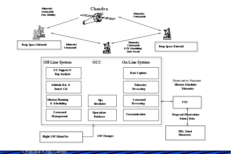
Chandra Telemetry Commands (Via Shuttle) Deep Space Network Telemetry Commands DSN Scheduling State Vector Telemetry Commands Off-Line System OCC S/C Support & Eng Analysis On-Line System Data Capture Attitude Det. & Sensor Cal Telemetry Processing Mission Planning & Scheduling Ops Simulator Command Processing Command Management Operations Database Communication Flight S/W Maint Fac Chandra X-ray Center Deep Space Network S/W Changes Observation Request Mission Schedules Telemetry CXC Proposed Observation Science Data IPIs, Guest Observers
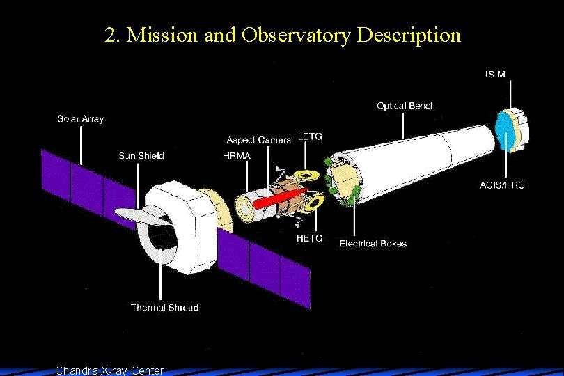
2. Mission and Observatory Description Chandra X-ray Center
Focusing X-rays Chandra X-ray Center
Chandra X-ray Center
Chandra X-ray Center
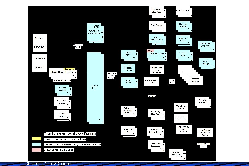
3. Spacecraft Systems u Command, Control and Data Management – 2 low gain antennas, 2 S-band transponders – Two solid state recorders, each 1. 8 GB – Redundant 16 -bit On Board Computers (OBC), interface units, command telemetry units, remote command telemetry units – 32 kbps telemetry with usual 24 kbps science and 8 kbps engineering u Electrical Power – Generates, stores and distributes electrical power to the spacecraft – 2 solar wings provide 2112 watts – 3 Ni Hydride batteries capacity 120 Amp hours for eclipses u Thermal Control – Passive elements include multi-layer insulation and radiators – Active elements include thermostats and sensors – OBC controls HRMA at 70 +/- 2. 5 deg with active elements Chandra X-ray Center
Spacecraft Subsystems u Propulsion – Integral propulsion system used for transfer orbit, deactivated – Momentum unloading propulsion system for unloading momentum from reaction wheels u Pointing Control and Attitude Determination – Sensors and control hardware to point, slew, solar array positioning and momentum unloading – Pointing requirements a modest ~30” due to photon counting nature of the science instruments – Pointing direction determined from aspect camera tracking 5 -8 stars and gyroscopes – Photon positions are reconstructed using aspect camera data during ground processing – Performance of aspect system gives ~3” absolute pointing, 0. 3” image reconstruction and 0. 6” celestial location – System includes 6 reaction wheels for attitude control, coarse and fine sun sensors for pointing without aspect camera – Spacecraft dithered during observations with ~16 arcsec Lissajous Chandra X-ray Center
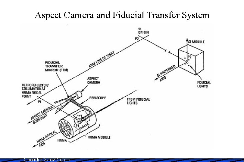
Aspect Camera and Fiducial Transfer System Chandra X-ray Center
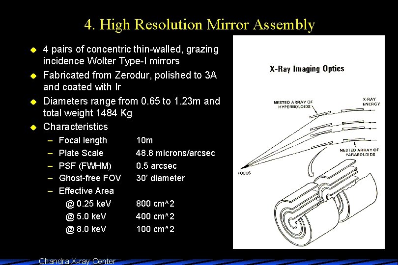
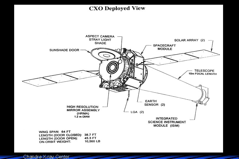
4. High Resolution Mirror Assembly u u 4 pairs of concentric thin-walled, grazing incidence Wolter Type-I mirrors Fabricated from Zerodur, polished to 3 A and coated with Ir Diameters range from 0. 65 to 1. 23 m and total weight 1484 Kg Characteristics – – – Focal length Plate Scale PSF (FWHM) Ghost-free FOV Effective Area @ 0. 25 ke. V @ 5. 0 ke. V @ 8. 0 ke. V Chandra X-ray Center 10 m 48. 8 microns/arcsec 0. 5 arcsec 30’ diameter 800 cm^2 400 cm^2 100 cm^2
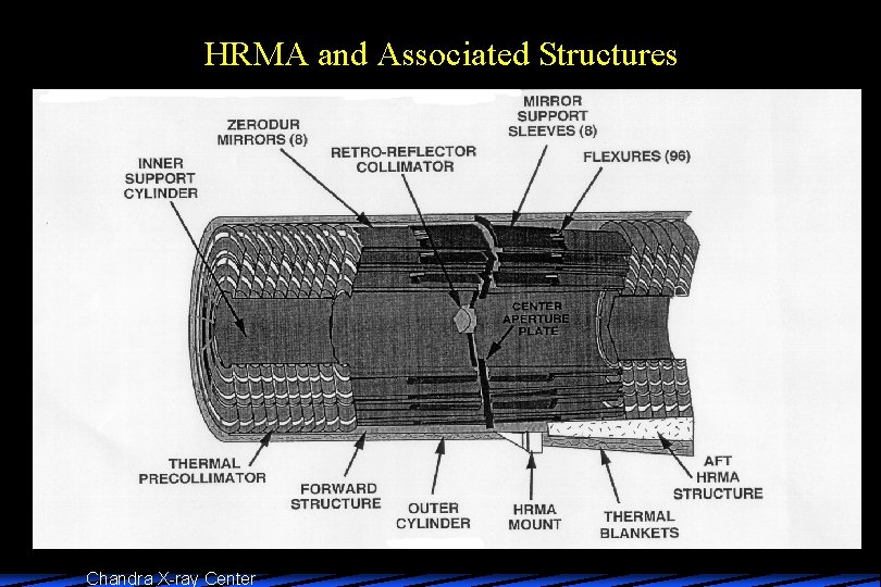
HRMA and Associated Structures Chandra X-ray Center
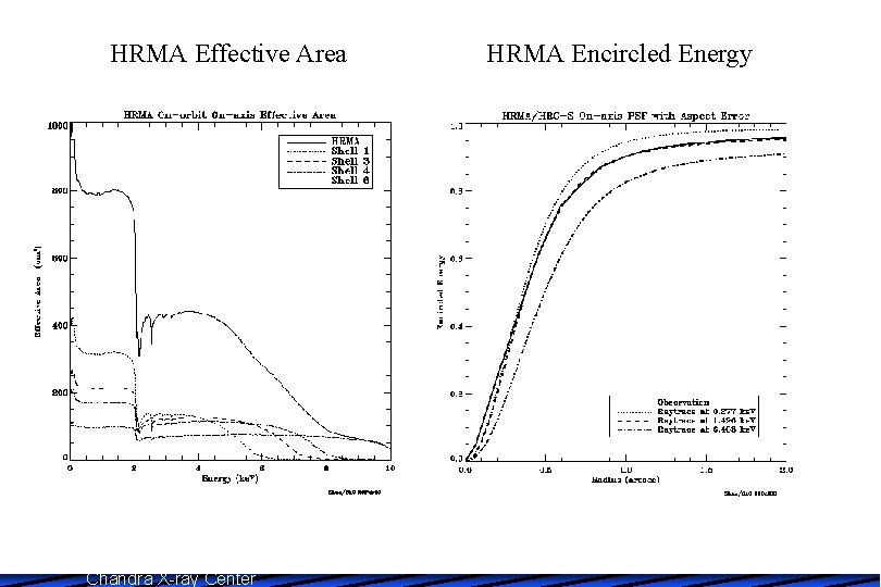
HRMA Effective Area Chandra X-ray Center HRMA Encircled Energy
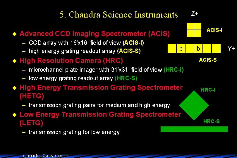
5. Chandra Science Instruments u ACIS-I Advanced CCD Imaging Spectrometer (ACIS) – CCD array with 16’x 16’ field of view (ACIS-I) – high energy grating readout array (ACIS-S) u Z+ b High Resolution Camera (HRC) b Y+ ACIS-S – microchannel plate imager with 31’x 31’ field of view (HRC-I) – low energy grating readout array (HRC-S) u High Energy Transmission Grating Spectrometer (HETG) HRC-I – transmission grating pairs for medium and high energy u Low Energy Transmission Grating Spectrometer (LETG) – transmission grating for low energy Chandra X-ray Center HRC-S
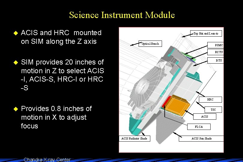
Science Instrument Module u ACIS and HRC mounted on SIM along the Z axis Top Hat and Lean-to Optical Bench PSMC RCTU u SIM provides 20 inches of motion in Z to select ACIS -I, ACIS-S, HRC-I or HRC -S BTU HRC u Provides 0. 8 inches of motion in X to adjust focus TSC ACIS FLCA ACIS Radiator Shade Chandra X-ray Center ACIS Sun Shade
Advanced CCD Imaging Spectrometer (ACIS) u Ten 1024 x 1024 pixel CCDs – – – u 2 x 2 array for imaging: ACIS-I labeled I 0 -I 3 1 x 6 array for imaging or spectroscopy: ACIS-S labeled S 0 -S 5 6 chips can be operated simultaneously Array Size 16. 9 x 16. 9 arcmin (ACIS-I), 8. 3 x 50. 6 arcmin (ACIS-S) Pixel Size 0. 49 arcsec 8 Front-illuminated and 2 back-illuminated chips – BI chips are S 1 and S 3 – BI response extends lower that FI – Average energy resolution of BI chips better than FI Chandra X-ray Center
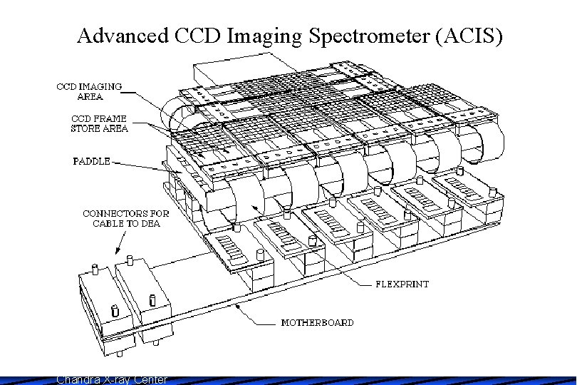
Advanced CCD Imaging Spectrometer (ACIS) Chandra X-ray Center
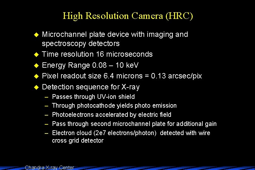
High Resolution Camera (HRC) u u u Microchannel plate device with imaging and spectroscopy detectors Time resolution 16 microseconds Energy Range 0. 08 – 10 ke. V Pixel readout size 6. 4 microns = 0. 13 arcsec/pix Detection sequence for X-ray – – – Passes through UV-ion shield Through photocathode yields photo emission Photoelectrons accelerated by electric field Pass through second microchannel plate for additional gain Electron cloud (2 e 7 electrons/photon) detected with wire cross grid detector Chandra X-ray Center
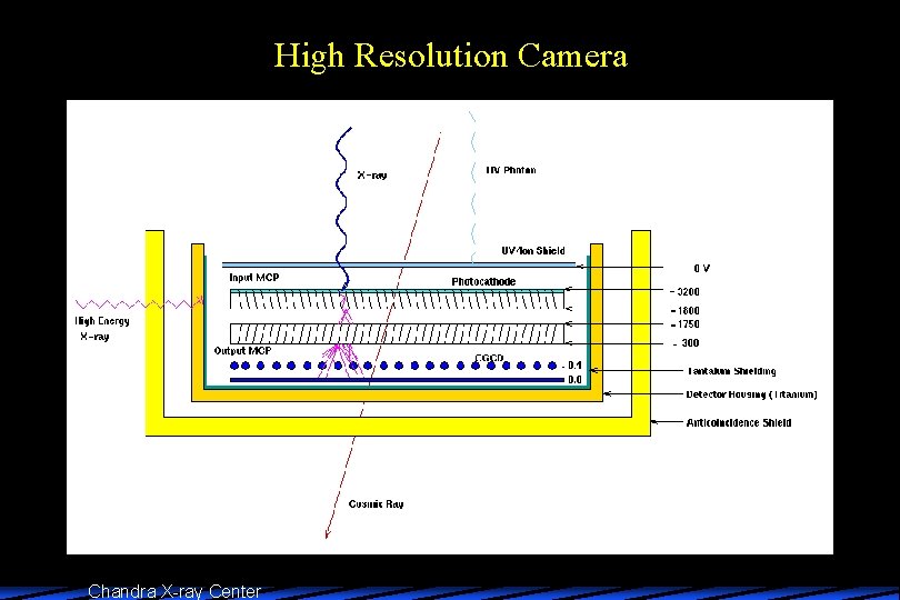
High Resolution Camera Chandra X-ray Center
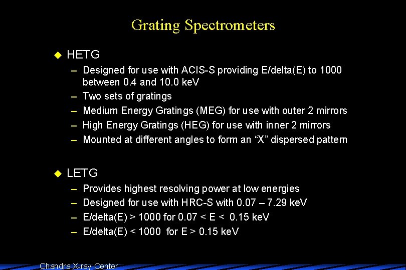
Grating Spectrometers u HETG – Designed for use with ACIS-S providing E/delta(E) to 1000 between 0. 4 and 10. 0 ke. V – Two sets of gratings – Medium Energy Gratings (MEG) for use with outer 2 mirrors – High Energy Gratings (HEG) for use with inner 2 mirrors – Mounted at different angles to form an “X” dispersed pattern u LETG – – Provides highest resolving power at low energies Designed for use with HRC-S with 0. 07 – 7. 29 ke. V E/delta(E) > 1000 for 0. 07 < E < 0. 15 ke. V E/delta(E) < 1000 for E > 0. 15 ke. V Chandra X-ray Center
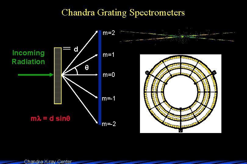
Chandra Grating Spectrometers m=2 Incoming Radiation d m=1 m=0 m=-1 m = d sin Chandra X-ray Center m=-2
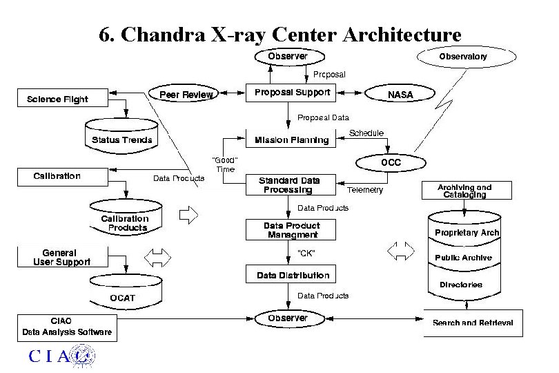
6. Chandra X-ray Center Architecture
Chandra X-ray Center
- Slides: 28