
CH 07 InputOutput External Devices IO Modules Programmed

- Slides: 60
CH 07 Input/Output • • External Devices I/O Modules Programmed I/O Interrupt-Driven I/O Direct Memory Access I/O Channels and Processor The External Interface: SCSI and Fire. Wire TECH CH 06 Computer Science
Input/Output Problems • Wide variety of peripherals Q Delivering different amounts of data Q At different speeds Q In different formats • All slower than CPU and RAM • Need I/O modules
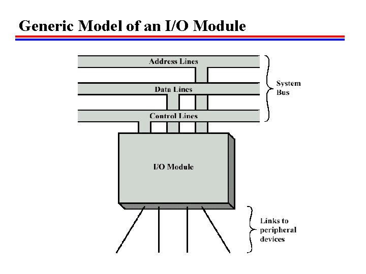
Input/Output Module • Interface to CPU and Memory • Interface to one or more peripherals • GENERIC MODEL OF I/O DIAGRAM 6. 1
Generic Model of an I/O Module
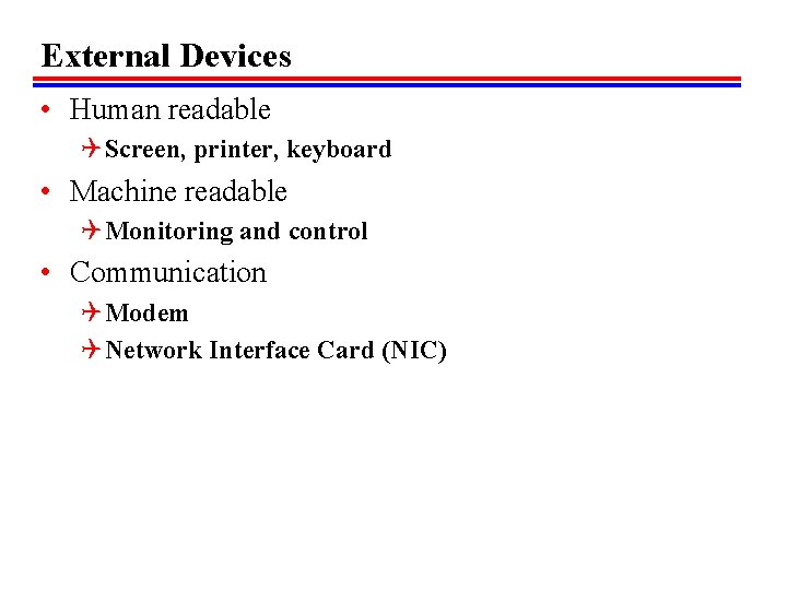
External Devices • Human readable Q Screen, printer, keyboard • Machine readable Q Monitoring and control • Communication Q Modem Q Network Interface Card (NIC)
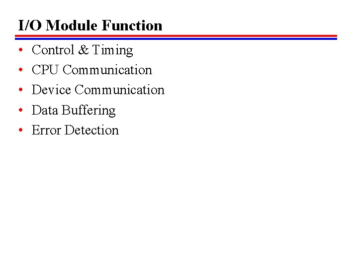
I/O Module Function • • • Control & Timing CPU Communication Device Communication Data Buffering Error Detection
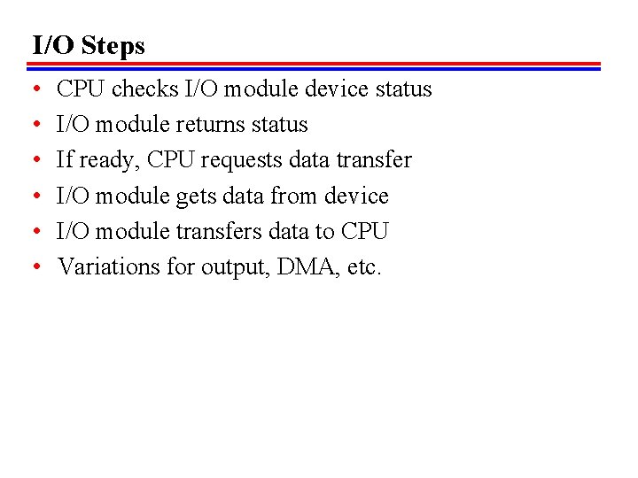
I/O Steps • • • CPU checks I/O module device status I/O module returns status If ready, CPU requests data transfer I/O module gets data from device I/O module transfers data to CPU Variations for output, DMA, etc.
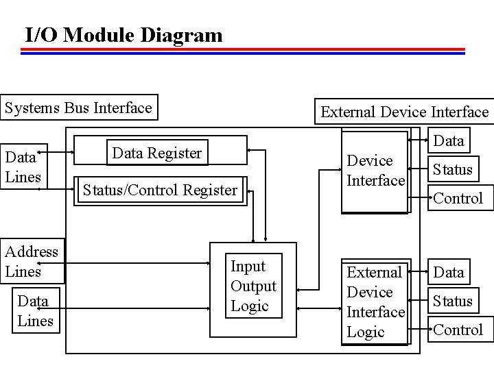
I/O Module Diagram Systems Bus Interface Data Lines Address Lines Data Lines External Device Interface Data Register Status/Control Register Input Output Logic External Device Interface Logic Data Status Control
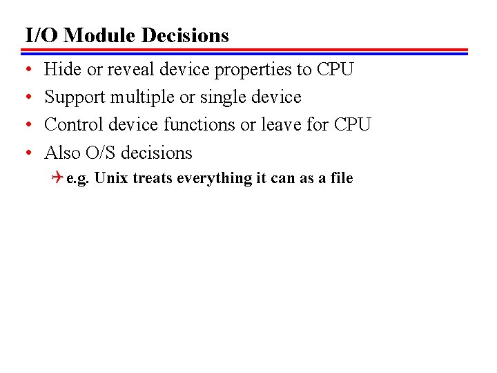
I/O Module Decisions • • Hide or reveal device properties to CPU Support multiple or single device Control device functions or leave for CPU Also O/S decisions Q e. g. Unix treats everything it can as a file
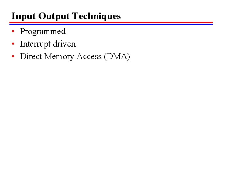
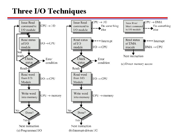
Input Output Techniques • Programmed • Interrupt driven • Direct Memory Access (DMA)
Three I/O Techniques
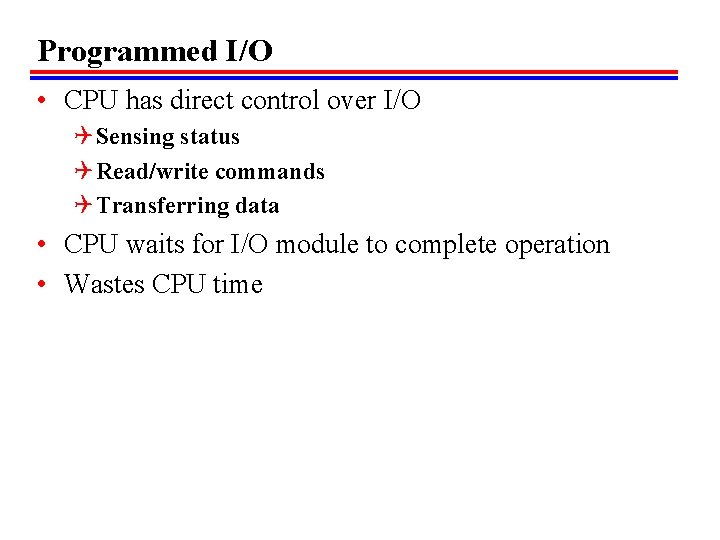
Programmed I/O • CPU has direct control over I/O Q Sensing status Q Read/write commands Q Transferring data • CPU waits for I/O module to complete operation • Wastes CPU time
Programmed I/O - detail • • CPU requests I/O operation I/O module performs operation I/O module sets status bits CPU checks status bits periodically I/O module does not inform CPU directly I/O module does not interrupt CPU may wait or come back later
I/O Commands • CPU issues address Q Identifies module (& device if >1 per module) • CPU issues command Q Control - telling module what to do fe. g. spin up disk Q Test - check status fe. g. power? Error? Q Read/Write f. Module transfers data via buffer from/to device
Addressing I/O Devices • Under programmed I/O data transfer is very like memory access (CPU viewpoint) • Each device given unique identifier • CPU commands contain identifier (address)
I/O Mapping • Memory mapped I/O Q Devices and memory share an address space Q I/O looks just like memory read/write Q No special commands for I/O f. Large selection of memory access commands available • Isolated I/O Q Separate address spaces Q Need I/O or memory select lines Q Special commands for I/O f. Limited set
Interrupt Driven I/O • Overcomes CPU waiting • No repeated CPU checking of device • I/O module interrupts when ready
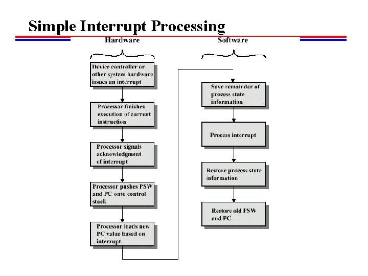
Simple Interrupt Processing
Interrupt Driven I/O Basic Operation • CPU issues read command • I/O module gets data from peripheral whilst CPU does other work • I/O module interrupts CPU • CPU requests data • I/O module transfers data
CPU Viewpoint • • Issue read command Do other work Check for interrupt at end of each instruction cycle If interrupted: Q Save context (registers) Q Process interrupt f. Fetch data & store • See Operating Systems notes
Design Issues // • How do you identify the module issuing the interrupt? • How do you deal with multiple interrupts? Q i. e. an interrupt handler being interrupted
Identifying Interrupting Module (1) • Different line for each module Q PC Q Limits number of devices • Software poll Q CPU asks each module in turn Q Slow
Identifying Interrupting Module (2) • Daisy Chain or Hardware poll Q Interrupt Acknowledge sent down a chain Q Module responsible places vector on bus Q CPU uses vector to identify handler routine • Bus Master Q Module must claim the bus before it can raise interrupt Q e. g. PCI & SCSI
Multiple Interrupts • Each interrupt line has a priority • Higher priority lines can interrupt lower priority lines • If bus mastering only current master can interrupt
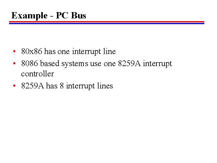
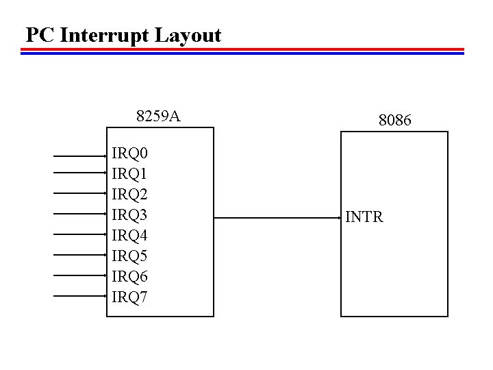
Example - PC Bus • 80 x 86 has one interrupt line • 8086 based systems use one 8259 A interrupt controller • 8259 A has 8 interrupt lines
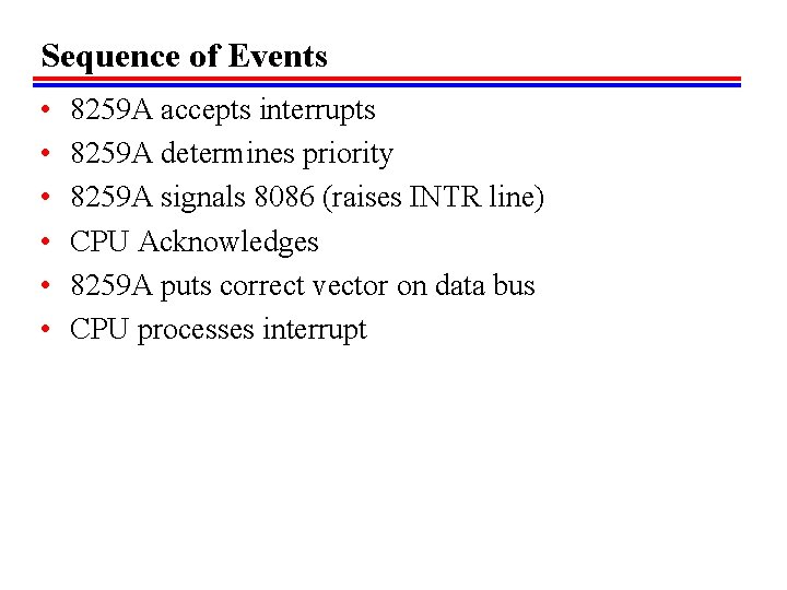
Sequence of Events • • • 8259 A accepts interrupts 8259 A determines priority 8259 A signals 8086 (raises INTR line) CPU Acknowledges 8259 A puts correct vector on data bus CPU processes interrupt
PC Interrupt Layout 8259 A IRQ 0 IRQ 1 IRQ 2 IRQ 3 IRQ 4 IRQ 5 IRQ 6 IRQ 7 I/O Module 8086 CPU INTR
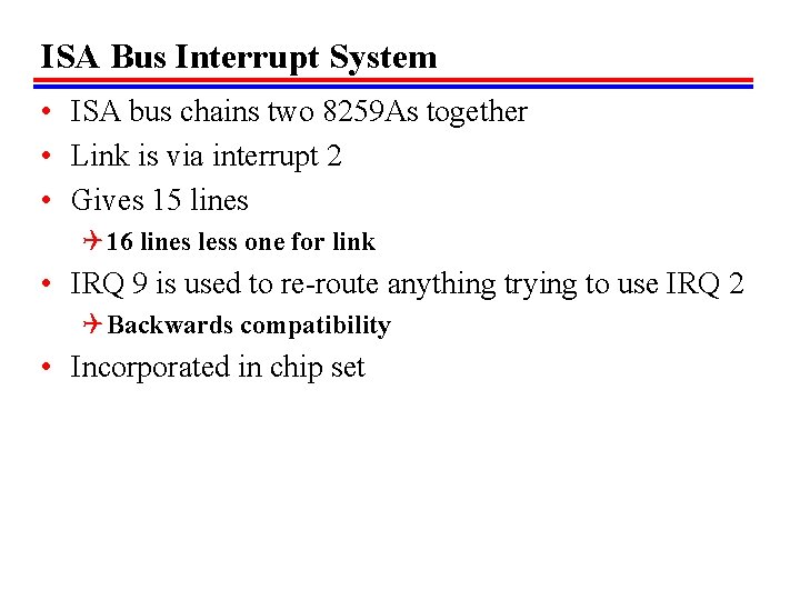
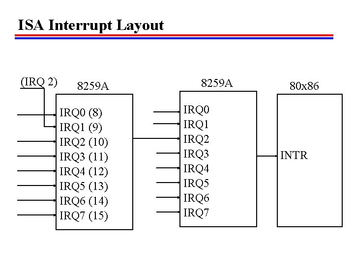
ISA Bus Interrupt System • ISA bus chains two 8259 As together • Link is via interrupt 2 • Gives 15 lines Q 16 lines less one for link • IRQ 9 is used to re-route anything trying to use IRQ 2 Q Backwards compatibility • Incorporated in chip set
ISA Interrupt Layout (IRQ 2) 8259 A IRQ 0 (8) IRQ 1 (9) IRQ 2 (10) IRQ 3 (11) IRQ 4 (12) IRQ 5 (13) IRQ 6 (14) IRQ 7 (15) 8259 A IRQ 0 IRQ 1 IRQ 2 IRQ 3 IRQ 4 IRQ 5 IRQ 6 IRQ 7 80 x 86 INTR
Foreground Reading // • http: //www. pcguide. com/ref/mbsys/res/irq/func. htm • In fact look at http: //www. pcguide. com/
Direct Memory Access • Interrupt driven and programmed I/O require active CPU intervention Q Transfer rate is limited Q CPU is tied up • DMA is the answer
DMA Function • Additional Module (hardware) on bus • DMA controller takes over from CPU for I/O
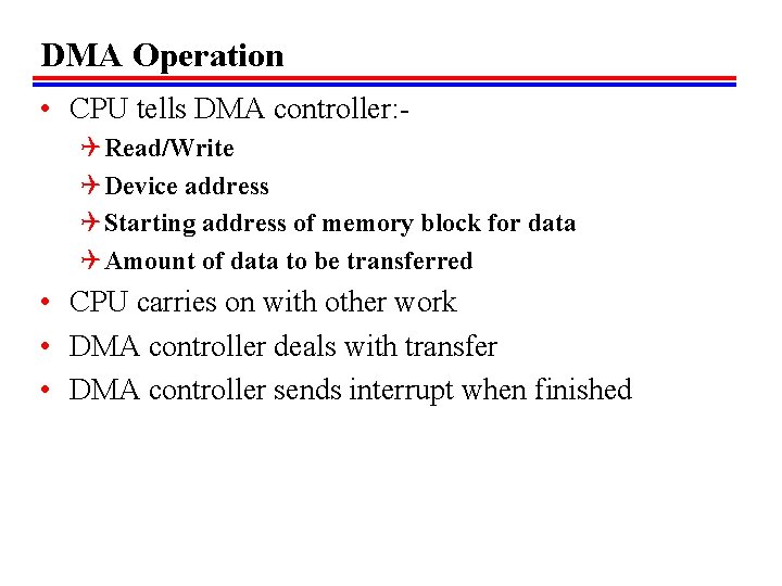
DMA Operation • CPU tells DMA controller: Q Read/Write Q Device address Q Starting address of memory block for data Q Amount of data to be transferred • CPU carries on with other work • DMA controller deals with transfer • DMA controller sends interrupt when finished
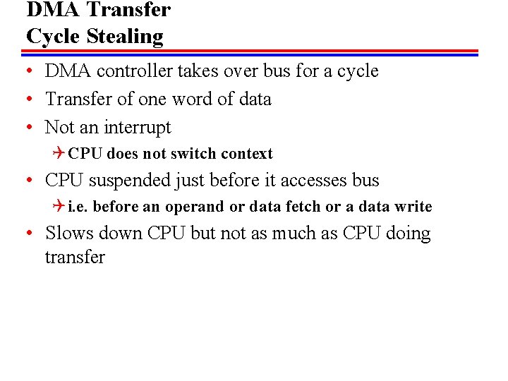
DMA Transfer Cycle Stealing • DMA controller takes over bus for a cycle • Transfer of one word of data • Not an interrupt Q CPU does not switch context • CPU suspended just before it accesses bus Q i. e. before an operand or data fetch or a data write • Slows down CPU but not as much as CPU doing transfer
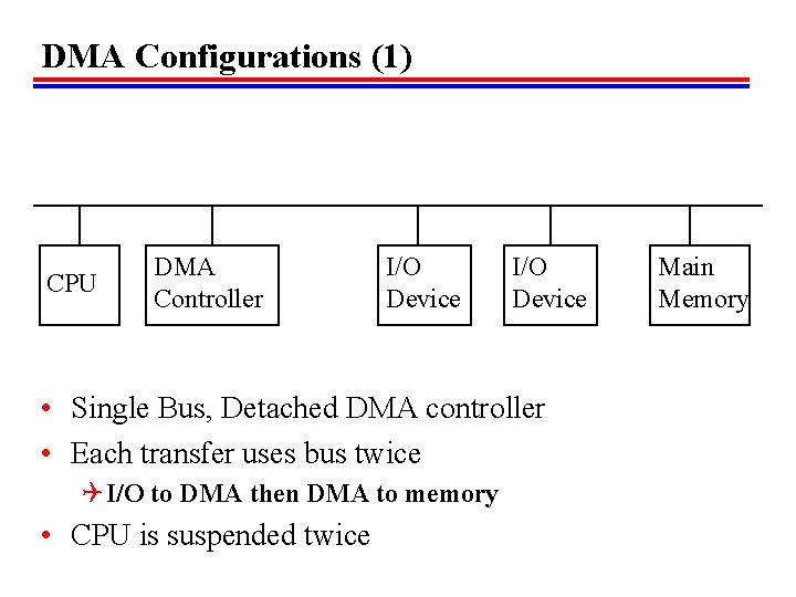
DMA Configurations (1) CPU DMA Controller I/O Device • Single Bus, Detached DMA controller • Each transfer uses bus twice Q I/O to DMA then DMA to memory • CPU is suspended twice Main Memory
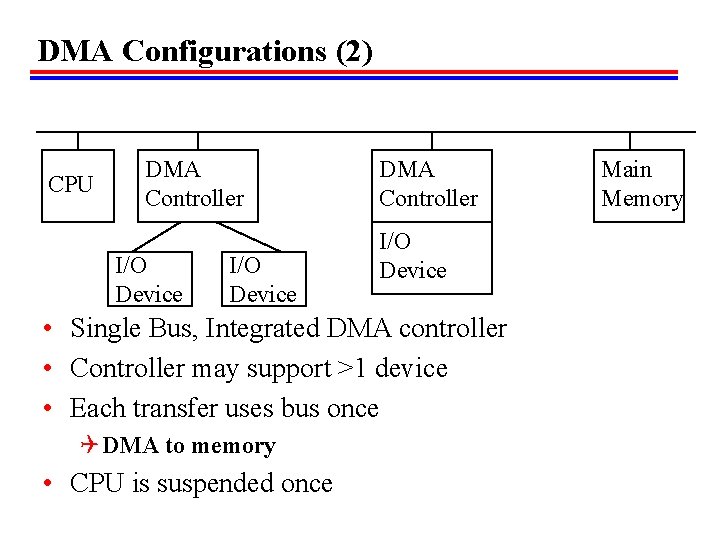
DMA Configurations (2) CPU DMA Controller I/O Device • Single Bus, Integrated DMA controller • Controller may support >1 device • Each transfer uses bus once Q DMA to memory • CPU is suspended once Main Memory
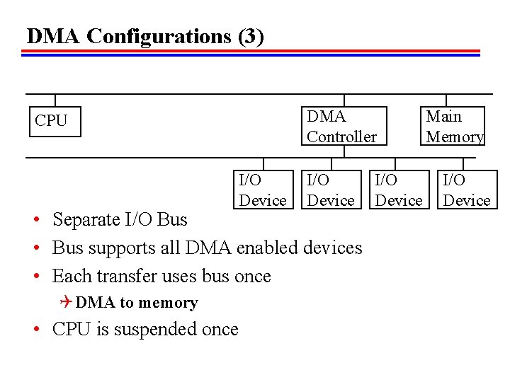
DMA Configurations (3) DMA Controller CPU I/O Device • Separate I/O Bus • Bus supports all DMA enabled devices • Each transfer uses bus once Q DMA to memory • CPU is suspended once I/O Device Main Memory I/O Device
I/O Channels • I/O devices getting more sophisticated Q e. g. 3 D graphics cards • CPU instructs I/O controller to do transfer • I/O controller does entire transfer • Improves speed Q Takes load off CPU Q Dedicated processor is faster
6. 7 External Interfacing • • • Connecting external devices together Bit of wire? Parallel interface; e. g. parallel port, SCSI Serial interface; e. g. serial port, Fire. Wire Point-to-point; e. g. keyboard, modem, display Multipoint; SCSI, Fire. Wire, USB, (Bus)
Small Computer Systems Interface (SCSI) • • • Parallel interface 8, 16, 32 bit data lines Daisy chained; host 7~d 0~d 1~…d 6~T Drive 7 has highest priority Devices are independent Devices can communicate with each other as well as host
Configuring SCSI • Bus must be terminated at each end Q Usually one end is host adapter Q Plug in terminator or switch(es) • SCSI Id must be set Q Jumpers or switches Q Unique on chain Q 0 (zero) for boot device Q Higher number is higher priority in arbitration
SCSI - 1 • • • Early 1980 s 8 bit 5 MHz Data rate 5 MBytes. s-1 Seven devices Q Eight including host interface
SCSI - 2 • • 1991 16 and 32 bit 10 MHz Data rate 20 or 40 Mbytes. s-1 • (Check out Ultra/Wide SCSI)
SCSI Signaling (1) • Between initiator and target Q Usually host & device • • Bus free? (c. f. Ethernet) Arbitration - take control of bus (c. f. PCI) Select target Reselection Q Allows reconnection after suspension Q e. g. if request takes time to execute, bus can be released
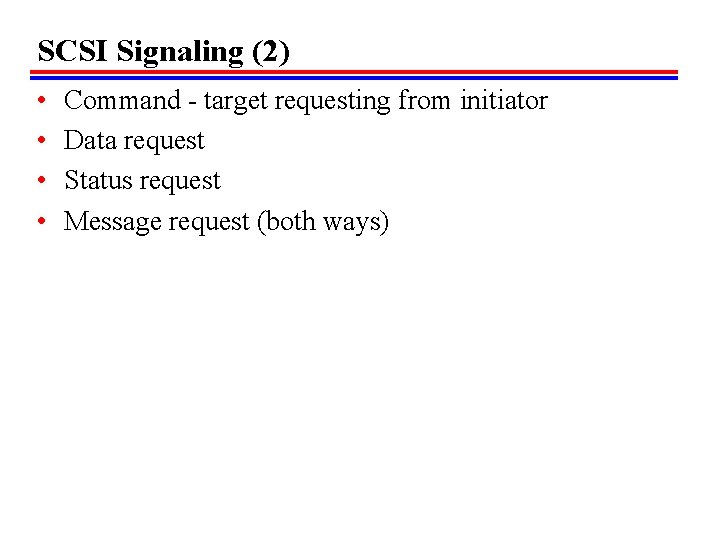
SCSI Signaling (2) • • Command - target requesting from initiator Data request Status request Message request (both ways)
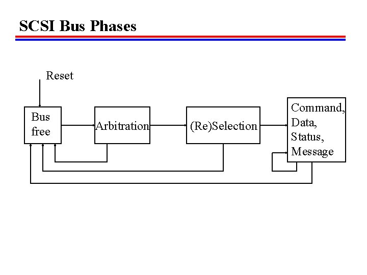
SCSI Bus Phases Reset Bus free Arbitration (Re)Selection Command, Data, Status, Message
SCSI Timing Diagram
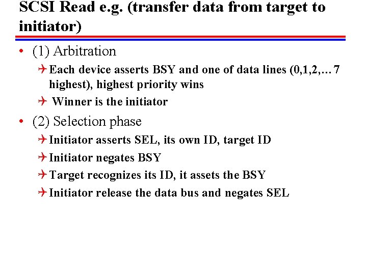
SCSI Read e. g. (transfer data from target to initiator) • (1) Arbitration Q Each device asserts BSY and one of data lines (0, 1, 2, … 7 highest), highest priority wins Q Winner is the initiator • (2) Selection phase Q Initiator asserts SEL, its own ID, target ID Q Initiator negates BSY Q Target recognizes its ID, it assets the BSY Q Initiator release the data bus and negates SEL
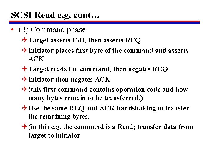
SCSI Read e. g. cont… • (3) Command phase Q Target asserts C/D, then asserts REQ Q Initiator places first byte of the command asserts ACK Q Target reads the command, then negates REQ Q Initiator then negates ACK Q (this first command contains operation code and how many bytes remain to be transferred. ) Q Use the same REQ and ACK handshaking to transfer the remaining bytes. Q (in this e. g. the command is a Read; transfer data from target to initiator
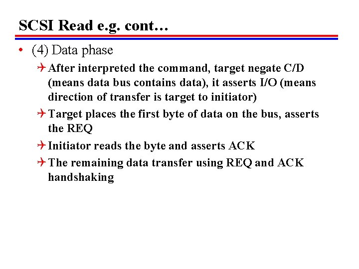
SCSI Read e. g. cont… • (4) Data phase Q After interpreted the command, target negate C/D (means data bus contains data), it asserts I/O (means direction of transfer is target to initiator) Q Target places the first byte of data on the bus, asserts the REQ Q Initiator reads the byte and asserts ACK Q The remaining data transfer using REQ and ACK handshaking
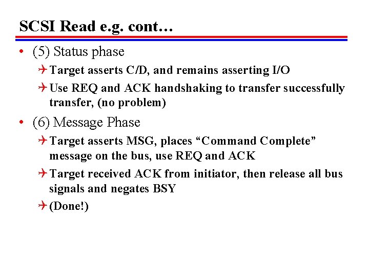
SCSI Read e. g. cont… • (5) Status phase Q Target asserts C/D, and remains asserting I/O Q Use REQ and ACK handshaking to transfer successfully transfer, (no problem) • (6) Message Phase Q Target asserts MSG, places “Command Complete” message on the bus, use REQ and ACK Q Target received ACK from initiator, then release all bus signals and negates BSY Q (Done!)
IEEE 1394 Fire. Wire // • • • High performance serial bus Fast Low cost Easy to implement Also being used in digital cameras, VCRs and TV Sony call this bus I-link.
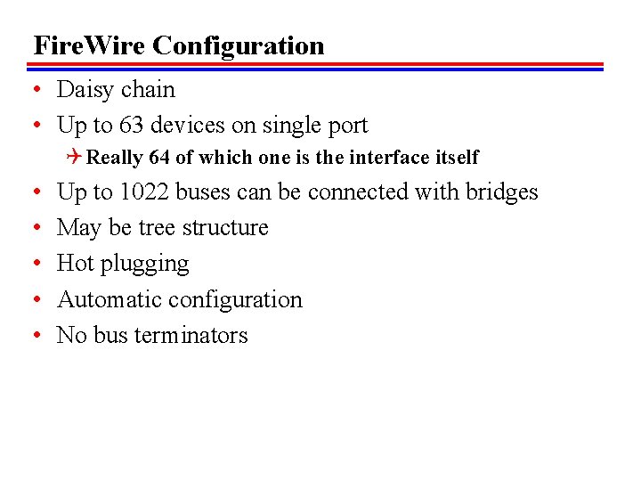
Fire. Wire Configuration • Daisy chain • Up to 63 devices on single port Q Really 64 of which one is the interface itself • • • Up to 1022 buses can be connected with bridges May be tree structure Hot plugging Automatic configuration No bus terminators
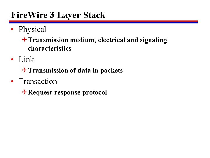
Fire. Wire 3 Layer Stack • Physical Q Transmission medium, electrical and signaling characteristics • Link Q Transmission of data in packets • Transaction Q Request-response protocol
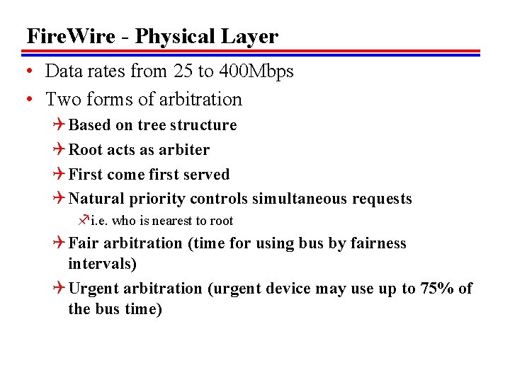
Fire. Wire - Physical Layer • Data rates from 25 to 400 Mbps • Two forms of arbitration Q Based on tree structure Q Root acts as arbiter Q First come first served Q Natural priority controls simultaneous requests fi. e. who is nearest to root Q Fair arbitration (time for using bus by fairness intervals) Q Urgent arbitration (urgent device may use up to 75% of the bus time)
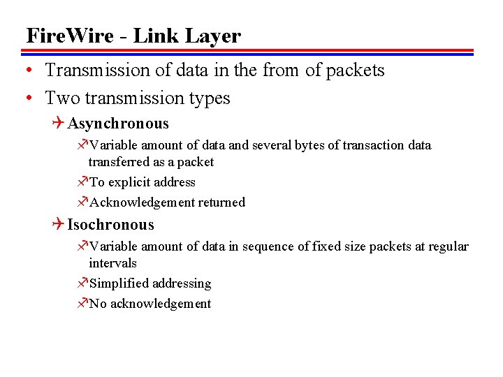
Fire. Wire - Link Layer • Transmission of data in the from of packets • Two transmission types Q Asynchronous f. Variable amount of data and several bytes of transaction data transferred as a packet f. To explicit address f. Acknowledgement returned Q Isochronous f. Variable amount of data in sequence of fixed size packets at regular intervals f. Simplified addressing f. No acknowledgement
Fire. Wire – Transaction Layer • Define a request-response protocol that hides the lower-layer details of Fire. Wire from applications • E. g. TCP/IP
Foreground Reading • Check out Universal Serial Bus (USB) • Compare with other communication standards e. g. Ethernet
Exercises • • Check up on-line slide show on: www. la. Tech. edu/~choi Read CH 6 Do Problems: Q 3. 1 Q 4. 2 & 4. 9 Q 5. 1 • Due BY Email to: choi@la. Tech. edu • Due by Wednesday