CFBC BOILER TUBE FAILURE ANALYSIS CASE STUDY Due

CFBC BOILER TUBE FAILURE ANALYSIS & CASE STUDY.

Due to shortcomings in traditional bubbling bed combustion, it is the need of time to develop the Circulating Fluidized Bed Combustion (CFBC) technology with advanced features. In this technology, crushed (6 – 12 mm size) fuel and limestone are injected into the furnace and particles remain suspended in a stream of flowing air in upward direction. The velocity in circulating beds remains in between 3. 7 to 9 m/sec. Then, the combustion takes place allowing the fine particles to eliminate out of the furnace with flue gas velocity of 4 to 6 m/s. Eventually, these particles are collected by the solid separators and circulated back into the furnace. It is desirable to achieve the maximum heat transfer outside the combustion zone, so, the circulating bed is designed to move a lot more solids out of the furnace area.


CFB Boiler overview

B&W IR-CFB Boiler Fuel Flexible Technology – Accepts wide range of fuels – Volatile matter, % 4 – 40 – Ash, % 0 – 60 – Heating value, Kcal/kg > 1500 – Moisture, % < 55 – Use of lower rank fuels reduces fuel costs – Fuel flexibility - minimizes fuel supply uncertainties – Ability to burn low cost and waste fuels

CFBC BOILER DESIGN COMPARISON


• Ash content of a coal is mostly tested at plant lab. This ash can be placed at 1200 deg C to know if it is agglomerating or not. In case the ash melts at lower temperature, the ash would become hard particle and would affect the erosion of the furnace wall panel. Such erosion will be a gross erosion of the wall tubes.

Refractory and tube are the main area that need to be checked

Main materials of construction of CFB boiler include: 1. Pressure part metals 2. Non-pressure part components 3. Structural load bearing components 4. Refractory materials

Pressure Part Materials Pressure parts include boiler components such as tubes, pipes, drum, and headers that are subjected to high internal pressure. For most subcritical CFB boilers, the choice of pressure parts materials is limited to conventional carbon steel and low alloy steel, but for supercritical boiler, one can go for superior alloys Specific choice is made considering the followings factors: • Strength at peak pressure and temperature • Heat transfer duty • Corrosion potential • Erosion potential

Ø Strength Requirements. The most important requirement of boiler tubes is to withstand the internal pressure throughout its life. The internal working pressure of water and steam in a CFB boiler is no different from that of conventional boilers. Thus, CFB designers can rely on the extensive experience of base conventional boiler design and various pressure vessel codes. Metal temperature is an important parameter in the choice of tube thickness as it is directly related to the allowable stress for various carbon steels and alloys.

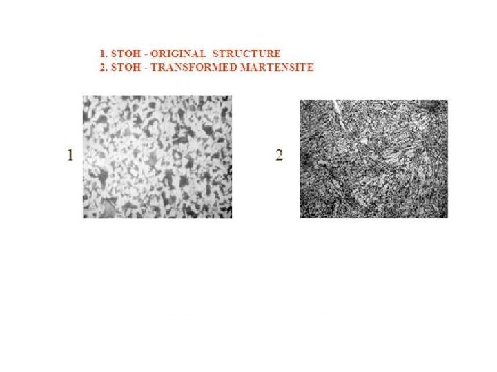
Creep is a special type of plastic deformation in which the strain increases slowly but continuously at constant stress that is below the yield stress. When the deformation reaches a definite limit, the material fails. So, creep life of the component for given service condition is a major consideration.

Ø Heat Transfer Duty The choice of tube materials does not affect the heat transfer much, but sometime, the heat flux through the tube surface affects the metal temperature and hence choice of materials. The allowable or the permissible stress on a metal decreases with increasing metal temperature

For extremely high heat flux, the designer may cover the tube with refractory to reduce the heat flux. This compromises the heat absorption but protects the tube against exposure to hostile abrasive environment and high metal temperature.
 is an important consideration in the design")
• Departure from nucleate boiling (DNB) is an important consideration in the design of boiler tubes. This phenomenon, which could be caused by high heat flux or stagnation of water in the tube could not only result in deposits leading to caustic gouging, but it could also result in sharp rise in tube wall temperature with severe reduction in strength. It is of particular concern in a supercritical boiler, and as such the mass flow through parallel tubes should be chosen such that uniform fluid flow through all tubes is ensured. When horizontal or slightly inclined tubes are used within the dense fluid bed heat exchanger (FBHE), care must be taken to avoid the DNB phenomenon. The occurrence of DNB can be avoided by several means like conservatively selecting higher water velocities inside the tubes, by the use of rifled tubes and by use of forced circulation

Corrosion Potential The corrosion issue in a coal or petcock-fired CFB boiler is not as critical as it is in other types of boilers due to the following reasons: • Low peak gas side temperatures (≲ 900 °C) • Lack of molten sticky ash deposits on tubes • Limited reducing zone, which is restricted to the refractory-lined area immediately above the grid but below the secondary air ports • Reduced SO 2 concentrations when limestone is used as a sorbent However, CFB boilers firing biomass, waste fuel or fuels containing chlorine, or alkali metals such as potassium could experience severe corrosion.

Two temperature regions of metal wastage due to corrosion Stainless steel (or more correctly austenitic steel) offers, for the most part, a higher resistance to corrosion at high temperatures than normal carbon or low chrome ferrite steels do. Chromium in steel provides oxidation and corrosion resistance. Stainless steel contains more chrome and nickel and is therefore two to three times more expensive than carbon steel. Stainless steel, however, is a wise investment in the long run, given that its lifetime can be up to five times longer than the carbon steels.

The corrosion rate or the metal wastage increases with metal temperature. In coalfired boilers, the corrosion of superheater and reheater tubes occurs at low temperature mainly by oxidation at a relatively low rate, but at higher temperature, complex liquid ash attack of corrosion takes place, resulting in a much higher rate of increase in metal wastage with temperature.

Ø Erosion Potential The most significant material problem facing a CFB designer and the operators is tube wastage by erosion The high solid densities encountered within the CFB combustor could be a challenge if a boiler is not properly designed or operated. Generally, erosion is a function of the impact angle and velocity of solids, solid density, velocity, particle hardness, particle shape, and the flow path geometry As the rate of erosion is highly dependent on velocity (proportional to velocity squared or cubed), it becomes the primary variable the designers would use to limit erosion in the convective passes of boilers Solid density is the next important factor influencing the erosion rate

Table shows the range of solid densities and velocities found in various zones of different types of boilers along with ranking as per the severity of erosion.
-fired boiler has very low solid")
• It is interesting that though pulverized-coal (PC)-fired boiler has very low solid density in the furnace, it ranks 2 nd, which is above CFB boiler furnace with solid density much above that in the PC boiler. This is due to the unique nature of solid motion in a CFB boiler furnace. we also note that erosion rate is a function of impact angle and it is lowest when the angle is zero, i. e. , the particle travel parallel to the target tube. This happens on the furnace wall of a CFB boiler. The furnace hydrodynamics is such that solids near the wall flow downward and parallel to wall tubes, and hence, the actual erosion rate is negligible on a vertical tube. This is in contrast with PC boilers, where particles move upward and hits the wall tube at an angle causing erosion.

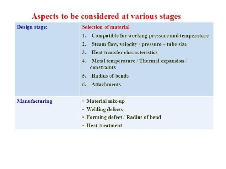
Selection of Tube Materials Selecting the right materials for a boiler component is one of the most complex technical issues at the planning and design stage. Essentially, it had to be ensured that the materials would safely and reliably resist the special operating conditions of the CFB boiler for an extended service period. For most subcritical CFB boilers, the largest portion of the tube surface, including the evaporative membrane wall, economizer surface, and low-temperature superheater, is made of low-carbon steel. More expensive alloys are then used selectively for the superheater/and reheater tubes and headers that operate at higher metal temperatures.

• the choice of tube metal would necessarily depend on the temperature the tube wall is exposed to, and it needs to be evaluated with adequate margin. The internal heat transfer coefficient of evaporator tube is much higher than that on the exterior of the tube. So, the metal temperature is closely related to the internal steam temperature and is less dependent on the external gas/solids temperature. For determining the strength of tube metal, its temperature is thus assumed to be a certain degrees above the temperature of the fluid (water or steam) it is carrying. For tubes in the evaporator, and for the superheater and reheater tubes, of a subcritical boiler, one can estimate the metal temperature, Tmetal, from the following thumb rule. • Tmetal = Tsaturated + 25 C (For evaporator) • Tmetal = Tsteam +50 C (for Superheater/Reheater)

• The steam temperature rises as it flows down the length of the superheater. So, the tube wall temperature of a superheater element would increase down the tube. The designer should therefore be careful about using the same tube metal temperature for designing all sections of the superheater.

Each CFB manufacturer optimizes material selection differently but follows some general application guides as given below: 1. Low-carbon and low-alloy steels are used for tubes, pipes, drum, and headers generally subjected to oxidizing conditions. 2. Refractory material is used for erosive and/or reducing conditions subjected to aggressive hot gas/solids. 3. Expansion joints (metallic or non-metallic) are used to adjust for the differential expansion between large boiler components, such as the cyclone and combustor

The location of use of these materials is shown in Fig The tubes in a CFB boiler, including those in evaporative, superheater, reheater, and water-wall surfaces, are subjected to internal pressure and exposed to hotter gas or solids on the outside. The headers and drum on other hand are exposed to internal pressure alone.

• These boiler tubes are normally placed in a variety of structural arrangements, including • Membrane wall in furnace or cyclone (water or steam cooled) • Tube bundles (superheater, reheater, and economizer) in the convective section, external heat exchanger (EHE) Support tubes used to support tube bundles • Pipes for headers and integral piping are subjected to internal pressure but no hotter medium on the outside.

• In CFB boilers, tube arrangements are different from those of conventional boilers. Such special arrangements include: • Fluidized bed heat exchanger bundles • Platen tubes (wing walls) inside Water-cooled air plenum • Water-or steam-cooled cyclonese the furnace

THE FUNCTION OF SOME IMPORTANT ALLOYING ELEMENTS Ø Chromium improves corrosion resistance in general. Ø Nickel is good against chlorine-induced corrosion, but poor against sulfur corrosion. Ø Molybdenum gives resistance against corrosion and oxidizing of the metal. Ø Aluminum is good against chlorine-induced corrosion and creates good oxide protection, but increases the cost of the steel. Ø Silica is good against chlorine, but may be affected by alkali metals. In coal-fired boilers, the chromium content of the steel is important (the higher the better). Ø In biomass-fired boilers, it is still unclear which material is best and why. High chrome content may have an advantage, but research shows that some steel types with very high chrome content perform poorly from the corrosion point of view. It is therefore important to evaluate many different types of steel.

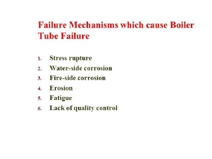
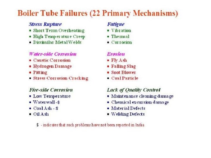
Major operating problems are divided under two broad groups: 1. Failure or degradation of boiler components 2. Reduced performance of the total plant or specific components

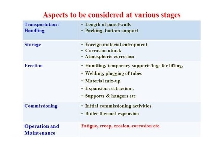
Degradation of Boiler Components Boiler outage could occur due to material degradation in various components of the boiler. It could occur through, corrosion, erosion, or abrasion as well as due to malfunction of specific components. The loss of boiler tube material is the biggest cause of forced outage in CFB boilers. Erosion and corrosion are two most important causes of the tube material failure. They are discussed below.

Erosion Issues in CFB Boilers • Erosion in a coal-fired power plant is recognized as the main cause of downtime due to outage accounting up to 50 – 75 % of the total forced outage and costing up to 54 %of the total production cost In general, the • extent of erosion in a CFB boiler furnace is lower than that in a PC-fired furnace while firing fuels with abrasive ash. This seems odd given the significantly higher • concentration of solids in a CFB furnace. A brief examination of the principle of • erosion could explain why CFB furnace is expected to have lower erosion that a • PC furnace experiences.

Principle of Erosion is removal of materials from a surface through contact with solids impacting on it. The process is similar to that of metal cutting but is different from the abrasion process. a particle impacts a ductile surface at an angle, α, with a velocity, Vp. The impact force has two components: a force normal to the surface causing deformation of the material and a force parallel to the surface, which removes the material from the surface. The erosion rate is a strong function of the impact angle, α. It is lowest when the impact angle is zero and when it is about 90°. Maximum erosion rate occurs when the particle hits at an impact angle of about 45°, but this angle is a function of the ductile material being eroded. In a CFB boiler, the solids near the wall travels downward parallel to it at a relatively low velocity of 1– 2 m/s while the gas velocity away from the wall may be in the range of 5– 10 m/s. Owing to such low angle of impact on the wall (*α = 0°) and low impact velocity, the erosion of wall tubes in a CFB boiler is nowhere in the range one would expect if solids were to impact the tubes at 45° at velocities closer to its superficial gas velocity. Such impact happens in bubbling fluidized beds, and for that reason, it experiences high rate of erosion of in-bed tubes.

FACTORS AFFECTING EROSION RATE • Fuel: Composition, shape, size, hardness, ash content: -CFB boilers are often used to fire hard coal, waste fuels with highly abrasive ash. Some CFB boilers fire low ash biomass as well, but the ash from such biomass contains high concentration of chemically active compounds such as sodium, potassium, sulfur, phosphorus, and chlorine, which can lead to higher levels of corrosion. The shape and size of the bed material also affects the erosion rate. For example, larger the particle and more angular its shape higher will be the erosion rate.

• Operating condition: Temperature, gas or particle velocity, and gas composition: -In the convection section of boiler, erosion rate depends directly on the velocity of the gas that carries eroding particles. The rate increases with increase in gas and particle velocity. This dependence is however not valid for CFB furnace owing to its different hydrodynamic condition. The effect of temperature on the erosion rate of tubes is not direct, but it could influence through changes in the properties of gas and strength of the tube metal.

Ø Tube properties: Composition and morphology of tube metal. Surface hardness, impact strength, and ductility of the surface being eroded influence its erosion rate. The crystallographic structure of the surface rather than the Vickers hardness alone determines the erosion of surface coatings on tubes. • Design and construction: Presence of extended surface: Erosion in the CFB boiler furnace generally does not occur if the wall tubes are perfectly vertical without any surface projection into the furnace, which could change the direction of downward flowing bed particles. This may happen during construction period owing to bad workman ship.

Example of incorrect workmanship during construction.

Following areas of a CFB boiler are particularly susceptible for erosion . q. Refractory in upper and lower parts of the furnace. q Refractories in bull nose, target areas, and sometimes the roof of the cyclones. q Nozzles of grid plates. q Water-wall tubes. q Suspended heat transfer surfaces in CFB furnace.

Erosion at the refractory and water wall interface inside the CFB furnace

Erosion at water-wall/refractory interface can be avoided by bending tube away from the erosion prone area

Horizontal shelves are placed on vertical water wall to reduce velocity and thickness of solids layer sliding down the water wall and thereby to minimize erosion on vertical wall tubes

Erosion of corner tubes in a 135 MW CFB boilers. Photograph on the right shows application of refractory to reduce the impact of erosion
 nozzles is also a major concern in CFB")
FLUIDIZING GRID Failure of distributor (grate) nozzles is also a major concern in CFB boilers. Common problems are blockage of orifices, slagging, erosion, tearing off of bubble caps, and backflow of bed material in the air plenum. Ideally, nozzles should not have any backflow of solid, but in practice, it happens. The particles dropped in the air box are picked up by incoming air and transported through the nozzle orifices. Typical orifice velocity being in the range of (50– 90 m/s) severe erosion of nozzle holes as well as walls of neighboring nozzles could occur. 5% nozzle may be replaced in every shut down. To avoid erosion of air nozzles, one could reduce the back sifting of solids in the air box or its prompt removal of those solids from air box. The exit hole of nozzles could be enlarged moving the orifice down inside the nozzle one can reduce the jet velocity and thereby reduce the erosion from it. Finally, to increase the life of the nozzle, one could use these out of material which would be wear-resistant, antioxidant,

Corrosion Issues in CFB Boilers • Beside erosion, other problems such as corrosion, slagging, scaling, deposition, and fouling also could occur causing damage to materials in a boiler. Sometime, erosion and corrosion occur simultaneously resulting in accelerated metal wastage in CFB boilers. These phenomena cause both failure of tubes and increased fuel consumption through decreased heat absorption. Corrosion can occur either on the outer or the inner surface of the tubes. Since the waterside corrosion inside the tubes is not much different from that in conventional type of boilers. In a typical fluidized boiler or combustor, the corrosion on external surface of tubes is triggered by one or more of the followings: • Fuels with high chlorine and sulfur content • Poor combustion control • High gas temperature • High metal temperature • Local reducing atmosphere • Tube surface erosion

Corrosion Mechanisms q An oxide layer (Fe 2 O 3 or Fe 3 O 4) or scale is formed on the exterior wall of steel tubes, subjected to oxidizing environment and this layer protects the tube from metal loss through further chemical reaction. Under certain situations, the combustion process could create local reducing environment through the formation of H 2 or CO. Such reducing condition could reduce the Fe 2 O 3 or Fe 3 O 4 to Fe exposing the metal for removal through other chemical reactions. The reason for high CO in the flue gas in many cases is unstable fuel feed, which occasionally causes the local air/fuel ratio to become substoichiometric. If the fuel contains sulfur, the reducing condition could form iron sulfide on the tube, which makes the scales non-protective, and the corrosion process starts. q Reasons: • Fluctuating environments (from oxidizing to reducing) set up complicated non equilibrium chemical reactions. • Smoldering unburnt fuel particles further release CO and HCl, which initiate reactions that penetrate porous scales and promote inter-granular attack of the tube material. • Sintered ash deposits on tubes prevent the access of oxygen to the tube surface, further encouraging the reducing conditions in the porous scales.

Chlorine-induced corrosion through active oxidation Mechanism of sulfur-induced corrosion

Boiler tube scale deposit measurement Excessive scale deposit on boiler tubes results in costly energy losses and excessive boiler unavailability. A well planned and executed boiler chemistry control program is essential to prevent tube failure. The inspection is performed using ultrasonic technology and proprietary software to accurately measure thickness of the deposit layer. The ability to measure boiler tube scale deposits allows for a more accurate chemical cleaning strategy - chemical cleaning cycles could be extended and the lifespan of your boiler can be improved.

BENEFIT There are numerous benefits to this approach, most notably the ability to measure tube scale deposit thickness with a direct correlation to the standard Deposit Weight Density (DWD-mg/cm 2) method. Internal scales in furnace tubes can be measured in hundreds of points, as compared to one point for standard DWD analysis. In addition, tube samples are taken only when and where they are needed. When scale growth is regularly monitored, corrective actions can be taken before corrosion risks increase.

PANEL SUPER HEATER TUBE FAILURE IN CFBC BOILER

OXIDE SCALE MEASUREMENT The very high temperatures found inside steam boilers (above 600 degree cent) can cause the formation of a specific type of hard, brittle iron oxide called magnetite on the inside and outside surfaces of steel boiler tubing. At very high temperatures, water vapor will react with the iron in the steel to form magnetite and hydrogen according to the formula: 3 Fe + 4 H 20 = Fe 3 O 4 + 4 H 2. Ø The speed of this reaction increases with temperature. Ø Oxygen atoms will diffuse inward through the magnetite layer, and iron atoms will diffuse outward, so the scale continues to grow even after the tube surface is completely covered. Ø Thermal conductivity of scale is only 5% of the parent metal. Ø Long term exposure to high temperatures, combined with the very high pressure inside the tube, leads to intergranular micro-cracking in the metal and to creep deformation (a slow swelling or bulging of the metal), which in turn eventually leads to tube failure by bursting. Ø A secondary issue is oxide exfoliation which damage turbine through carry over with steam.

Ultrasonic technique • The ultrasonic method for measuring scale thickness is based on transmitting a wave through the tube thickness. The thickness is calculated by measuring the time difference between the signals reflected from the steel/scale interface and the tube ID surface. With advanced signal interpretation techniques, we can achieve Oxide scale Thickness measurements up to the resolution of 0. 15 Microns. ultrasonic thickness gages that can be used with relatively high frequency (20 MHz) broadband, single element transducers, and that incorporate software that is capable of detecting appropriate echoes and measuring the short time interval between the two echo peaks that represent the steel/oxide and oxide/air boundaries, as seen in any ultrasonic gaging application, the instrument measures the time intervals between relevant echoes and then uses a calibrated sound velocity value to calculate thicknesses.

In the waveform at left, the large echo at the left side of the screen represents the outside surface of the tube, the smaller peak at the right side of the screen represents the steel/oxide boundary, and the large echo at right represents the inside surface of the oxide. Waveform on right has been zoomed to show details of oxide echo shape.

The oxide scale thickness were measured using optical microsco pe . Ø Determination of thickness of oxide layer has been used in recent years for the purpose of life assessment and failure analysis of components operating at high temperatures. Oxide scale thickness measurements permit the estimation of exposure time or temperature. The temperatures of the upper section of the tubes were estimated based on the oxide scale thickness of the steam side of the tube, by using the following equation that specifically applies to 1 -3% Cr steels : log X = 2. 1761× 10 -4 (T) (20+ log t) -7. 25 where, X is the scale thickness in mils (1 mm = 40 mils), T is the temperature and t is the operational time in hours. Using equation the average measurements were used to determine the approximated temperatures at theses tubes.

Optical micrograph of Fireside oxide scale showing thick layer with some spallation and intact steam side oxide scale

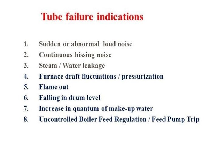
Operation issues responsible for tube leakage

Drum LVL Very Low

Drum Level very high

Furnace draft very high

Bed Temperature High

Bed Temperature Low

Water wall/Screen tube/ Evaporator Tube leakage

Super heater Tube failure

High Super heater Temperature

Low super heater Temperature

Flame Failure

Furnace Explosions

Explosive Power of Boiler

Furnace Explosion in CFBC Boiler

Type of Explosion in CFBC

Dust Explosion

FIRE TRAINGLE & EXPLOSION PENTAGON

Philosophy of Explosion prevention.

Furnace explosions in CFBC boilers are rare when both bed and free board temperatures are above 760 deg C. Chances of explosions are very high when these temperatures are below 540 deg C. Though not fully established, yet chances of explosions cannot be ruled out when bed temperature remains between 540 deg C and 760 deg C CASE STUDY: -This is a case study of a boiler explosion in a 85 TPH CFBC boiler fired with imported coal. The boiler had a furnace explosion after 12 hrs a fresh start up. There were extensive damages to buck stay, boiler water wall and economizer casing. The incident took place a month before. The boiler was offered for inspection after cleaning. The boiler insulation was removed almost fully so that the water wall rectification wok can be commenced. Chronology of events: Ø Boiler was started on 1. 30 AM on first day. Ø Boiler was connected to main steam header at 6. 30 AM on the first day. Ø Boiler was running at a load of 43 TPH till 11. 30 PM on the first day. Ø Coal was not being fed to furnace at 00. 10 hrs on second day. Ø There was an incident of furnace high pressure trip prior to incident of explosion. PA fan and SA fan got tripped. Fans were restarted at 00. 35 hrs. Coal feed was initiated at 00. 38 hrs. Just after 00. 40 hrs furnace explosion took place.

Review of log sheet and trend: Duration between 11. 31 of first day to 00. 11 of second day. 1. Bed temperature was at 830 deg C average 2. The furnace pressure was hunting between -20 mm. WC and -50 mm. WC. 3. PA air flow had been 80 -84 TPH, which is almost the full load air flow. 4. SA flow was in between 131 to 137 TPH though the load was 73 TPH. 5. Air box pressure had been +1200 mm. WC to +1275 mm. WC. 6. Main steam flow had been 43 -44 TPH. 7. Oxygen went up from 10. 14 % to 13. 18% at 00. 13 hr Duration between 00. 11 of second day to 00. 20 of second day 1. Bed temperature came down to 636 deg C. 2. As the oxygen went up to 18%, it was clear that there was no coal flow to the furnace. 3. Coal feeder rpm was raised from 6. 5 -12. 5 -14. 5 -20. 4. PA air flow had been 80 -84 TPH, which is almost the full load air flow. However PA fan. VFD was brought down from 85 to 74. 5. ID VFD remained at 81. 6. Air box pressure had come down from 1200 mm. WC to 1000 mm. WC. 7. Main steam flow came down to 21 TPH. 8. SA flow remained at 134 TPH and SA pressure was at 640 mm. WC. 9. Furnace draft increased from -40 mm. WC to -90 mm. WC. 10. PA fan, SA fan and fuel feeder, DCF tripped at 00. 20 hrs. 11. In the one minute interval data, there is no record of furnace pressure going high. However on furnace pressure high activation only the feeders, PA and SA got tripped.

Duration between 00. 20 of second day to 00. 40 of second day 1. 1. The PA fan and SA fan were brought in service. 2. PA pressure went up to 1096 mm. WC. 3. The coal feeder rpm was at 15 for three minutes. Then it was reduced to 8. 4. SA discharge pressure was at 433 mm. WC. 5. The PA fan VFD was at increased up to 78%. 6. Suddenly the ID fan VFD input was changed from 75% to 20% by operator. Just at this point the furnace pressure had gone high and resulted in explosion. The reduction of ID fan VFD made the furnace pressure to + ve. Yet there must be fuel rich situation for the incident to occur. There were two possibilities of fuel accumulation. Explanation: 1. -Actually coal flow was there from feeder and it might have accumulated in the fuel feed pipe without entering in to furnace. At one point the fuel could have come in to furnace. For a steam load of 45 TPH the feeder speed was 6. 5. Approximately the coal feed rate had been 10 TPH. In a minute the feeder can feed 167 kg for 1% rpm. Cumulatively there must have been coal feed to an extent of 3384 kg of coal for the period of coal flow problem. Out of this the coal must have burnt to an extent of 50% since the steaming was at a rate of 20 TPH. There can be a balance of coal to about 1700 kg inside the coal pipe which got fed suddenly. The bed inventory can be about 7740 kg for a bed height of 600 mm. This will leave a coal percent of 18% in the bed. But the VM was about 40%, which got used up in explosion. The remaining coal in bed should have been 10. 8%. Under normal condition the carbon percent in a fluidized bed does not exceed 1. 5%. This proves there was coal accumulation

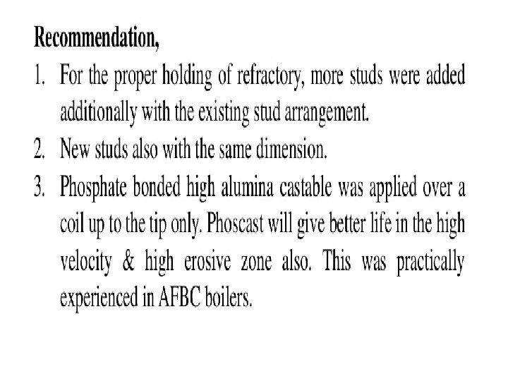
Explanation: -2. Coal burning needs adequate air flow for combustion. In case of excess air flow, coal will accumulate without combustion. When there is PA flow / SA flow reduction, the accumulated coal could burn rapidly. The first trip which occurred was at 00. 20 hrs. This time the furnace was dilute. There was no coal flow for a period. As the furnace was with excess air, the coal stopped burning. As fuel flow was raised and air flow was brought down, the furnace pressure went high due to sudden burning of high VM fresh coal. The same situation was occurred during the explosion. The fuel flow was increased and ID fan rpm & damper was reduced drastically. On pressurization of furnace, the accumulated coal had burnt rapidly. This had resulted in explosion. It was informed that when the LOI of bed material was analyzed to be 12%. It meant that there was sufficient accumulation of fuel without burning. RECOMMENDATIONS The loading of the boiler has to be done with regulated air flow, fuel flow and bed material flow. Without bed material addition, the load rise will take time in a CFBC boiler. With less bed material, the rise and fall of bed temperature will be abrupt during feeder rpm change. The combustion is in the form of suspension firing rather than a fluidized bed firing. In this plant, the fuel spreader air was taken from SA. Initially the SA flow would be less and thus the SA pressure would be less. With less SA pressure fuel spreading would not be proper. The fuel spreading air shall be tapped from wind box itself, where the PA pressure is always in the range of 1000 mm WC to 1200 mm WC. An explosion door can be added to upper furnace. Rupture disc can also be another choice. In the present design, the fuel port is made of refractory. Refractory surface not being smooth can accumulate fuel. Air cooled plate formed chutes are recommended.

EXTENT OF DAMAGE On inspection of the furnace, it was clear that the water wall got opened due to improper closure of the buck stay at corners. If the buck stays were closed properly, the water wall would not have got distorted. Instead some other weak point such as APH hopper could open up. The economizer casing got opened up since casing stiffeners were not closed at all. Stiffening is incomplete, if the corners were not closed. The photos explain the designer’s and erector’s mistakes that led to more damage to the combustor panels CONCLUSION Knowledge of minimum fluidization air flow is very essential during start up. With less air flow and with less fuel, the continuous combustion has to be established. High SA flow during start up, results in quenching of the fire. This explosion is a result of confused state of the operation team during startup. The boiler manufacturer did not consider explosion doors which are essential these days wherein high VM coals are used. Once we know that there is excess fuel inside the furnace, the ID draft alone has to be increased to avoid a mishap.

Furnace Exploded

Boiler Pressure High

PAH/SAH Tube failure

PROCEDURES FOR BOILER TUBE FAILURE ANALYSIS Proper investigative procedures are needed for accurate metallurgical analysis of boiler tubes. Depending on the specific case, macroscopic examination combined with chemical analysis and microscopic analysis of the metal may be needed to assess the primary failure mechanism(s). Failed tube section is removed from a boiler must be free from contamination of deposits and damage. The tube should be properly labelled with its location and orientation.
 is a versatile technique that allows inorganic chemical")
Scanning electron microscope-energy dispersive spectroscopy (SEM-EDS) is a versatile technique that allows inorganic chemical analysis on a microscopic scale. SEM-EDS analyses are shown in Figures. SEM-EDS can determines 1. differences in deposit composition between corroded and noncorroded areas on a tube surface 2. The extent to which under deposit concentration of boiler salts on heat transfer surfaces is promoting corrosion damage. 3. elemental differences between visually different tube surface deposits. SEM EDS image
 An SEM uses a vacuum in which high")
PRINCIPLE OF SCANNING ELECTRON MICROSCOPE (SEM) An SEM uses a vacuum in which high voltage generates an electron beam. The beam, focused by electrical lenses and scanned over the surface of the substrate, Generates secondary electrons that escape from the surface. The intensity of the escaping electrons depends mainly on the atomic mass of the surface and somewhat on their crystal orientation. These secondary electrons are detected and create a black-and-white image with varying intensity, just like a common black-and-white photograph

Limiting factors that must be considered when using SEM /EDS are: Chamber size: -5 by 5 cm Chamber environment: -Vacuum Specimen radius A small-diameter pipe with a tight radius restricts the study area to just one area at a time because of focus issues. Specimen conductivity. Substrates with poor conductivity may disturb the electron beam, which can be overcome by using a thin gold film plating. This usually isn’t a problem in the tube and pipe industry because most corrosion appears on conductive substrates.

This surface is severely damaged from etching. The holes areas that have been contaminated with oil. In general, etching follows the grain borders of the iron crystals where, under some conditions, localized corrosion occurs (often pinholes).

This surface has less damage from etching and shows a contaminated spot. The upper black line is from a marker. Marking the sample helps to find corrosion locations. (EDS ANALYSIS) When an electron beam of sufficient energy hits a surface, it creates X-ray radiation. The wavelength of the reflected energy depends on the atom that the electron beam hits. The energy from the electron beam pushes some of the object’s electrons to higher orbits; when they fall back to their original orbits, they release energy as quantum. The spectrum is X-ray and the wavelength depends on which orbit the electron returns to. The electron beam penetrates to a known depth, meaning that the rebounding X-ray maps the substrate layer. The penetration depth is a function of the atomic weight and acceleration voltage of the electron beam. Common acceleration voltages are 10 k. V and 20 k. V, which penetrate iron to a depth of 2 µm and 7µm, respectively, and carbon to 3. 3 µm and 10. 7 µm, respectively. As a result, a mixture of carbon and iron appears more carbon like as the acceleration voltage increases, making quantitative analysis of surface layers rather complex.
 Ø EDS cannot detect atoms with very low mass, such as")
ENERGY DISPERSIVE SPECTROSCOPY(EDS) Ø EDS cannot detect atoms with very low mass, such as hydrogen, lithium, beryllium, and helium. Ø Nitrogen can be detected, but it might be missed since many nitrogen-containing chemicals are not stable in a vacuum. However, nitrogen in well-bound structures such as proteins and titanium nitride coatings is easily detectable. Figure the results show high amounts of carbon, which can be explained from the organic residue on the tube. Iron may develop from rust, iron soap, or other iron structures, in addition to the steel substrate. Pure steel (cold-rolled without scale) normally shows more than 75 percent iron by weight and some carbon, usually 5 to 10 percent. This carbon does not represent the carbon in the lowcarbon steel matrix, which is less than 0. 4 percent, but is related to the carbon absorbed at the surface because iron has a very strong tendency to do this. Even uncorroded steel exhibits 5 to 10 percent oxygen, which comes from the natural passivation of iron in the presence of oxygen.

THANK YOU
- Slides: 107