
CEPC Magnet System CHEN Fusan KANG Wen November

CEPC Magnet System CHEN, Fusan KANG, Wen November 5, 2017
Outline • CEPC collider magnet • • Overview Design of the dual aperture dipole Design of the dual aperture quadrupole Design of the sextupole • CEPC booster magnet (provided by KANG, Wen) • Overview • Design of the low field dipole • Test of the low field dipole prototype 2/24
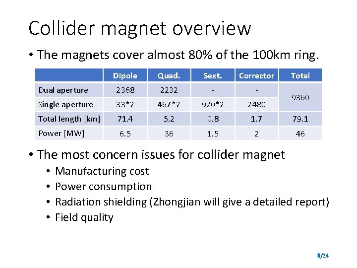
Collider magnet overview • The magnets cover almost 80% of the 100 km ring. Dipole Quad. Sext. Corrector Total Dual aperture 2368 2232 - - Single aperture 33*2 467*2 920*2 2480 Total length [km] 71. 4 5. 2 0. 8 1. 7 79. 1 Power [MW] 6. 5 36 1. 5 2 46 9360 • The most concern issues for collider magnet • • Manufacturing cost Power consumption Radiation shielding (Zhongjian will give a detailed report) Field quality 3/24
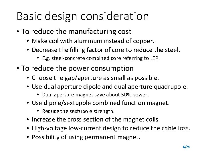
Basic design consideration • To reduce the manufacturing cost • Make coil with aluminum instead of copper. • Decrease the filling factor of core to reduce the steel. • E. g. steel-concrete combined core referring to LEP. • To reduce the power consumption • Choose the gap/aperture as small as possible. • Use dual aperture dipole and dual aperture quadrupole. • Dual aperture magnet save about 50% power. • Use dipole/sextupole combined function magnet. • Reduce the sextupole strength. • Increase the cross section of the magnet coils. • High-voltage low-current design to reduce the cable loss. • Possibility of using permanent magnet. 4/24
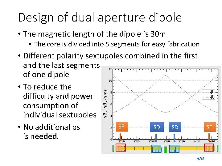
Design of dual aperture dipole • The magnetic length of the dipole is 30 m • The core is divided into 5 segments for easy fabrication • Different polarity sextupoles combined in the first and the last segments of one dipole • To reduce the difficulty and power consumption of individual sextupoles SF SD SD • No additional ps is needed. 5/24 SF
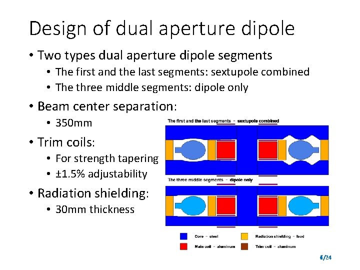
Design of dual aperture dipole • Two types dual aperture dipole segments • The first and the last segments: sextupole combined • The three middle segments: dipole only • Beam center separation: • 350 mm • Trim coils: • For strength tapering • ± 1. 5% adjustability • Radiation shielding: • 30 mm thickness 6/24
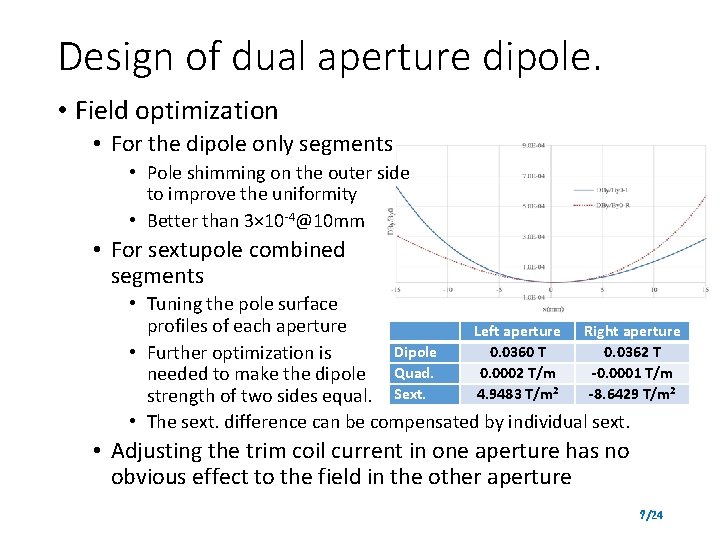
Design of dual aperture dipole. • Field optimization • For the dipole only segments • Pole shimming on the outer side to improve the uniformity • Better than 3× 10 -4@10 mm • For sextupole combined segments • Tuning the pole surface profiles of each aperture Left aperture Right aperture Dipole 0. 0360 T 0. 0362 T • Further optimization is 0. 0002 T/m -0. 0001 T/m needed to make the dipole Quad. 4. 9483 T/m 2 -8. 6429 T/m 2 strength of two sides equal. Sext. • The sext. difference can be compensated by individual sext. • Adjusting the trim coil current in one aperture has no obvious effect to the field in the other aperture 7/24
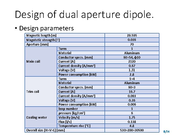
Design of dual aperture dipole. • Design parameters Magnetic length [m] Magntetic strength [T] Aperture [mm] Turns Material Conductor specs. [mm] Current [A] Main coil Current density [A/mm 2] Voltage [V] Power consumption [k. W] Turns Material Conductor specs. [mm] Current [A] Trim coil Current density [A/mm 2] Voltage [V] Power consumption [k. W] loop number pressure [kg/cm 2] Cooling water Velocity [m/s] Flux [l/s] Temperature rise [°C] Overall size (H×V×L) [mm] 29. 565 0. 036 70 1 Aluminum 60× 54, φ10 2120 0. 67 1. 31 2. 8 1× 4 Aluminum 60× 3 16. 7 0. 093 0. 36 0. 006 1 6 1. 75 0. 138 4. 8 530× 200× 30500 8/24
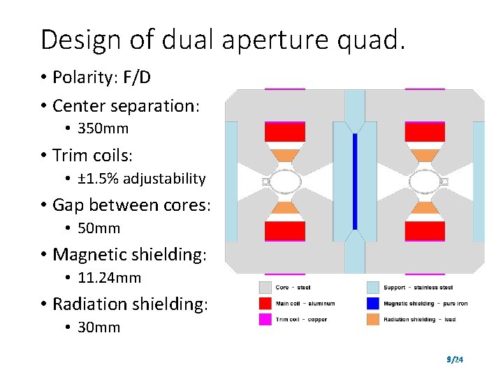
Design of dual aperture quad. • Polarity: F/D • Center separation: • 350 mm • Trim coils: • ± 1. 5% adjustability • Gap between cores: • 50 mm • Magnetic shielding: • 11. 24 mm • Radiation shielding: • 30 mm 9/24
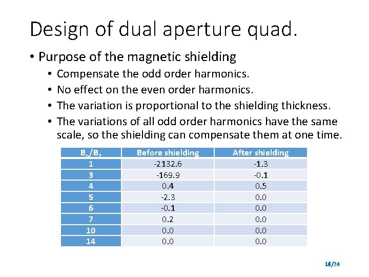
Design of dual aperture quad. • Purpose of the magnetic shielding • • Compensate the odd order harmonics. No effect on the even order harmonics. The variation is proportional to the shielding thickness. The variations of all odd order harmonics have the same scale, so the shielding can compensate them at one time. Bn/B 2 1 3 4 5 6 7 10 14 Before shielding -2132. 6 -169. 9 0. 4 -2. 3 -0. 1 0. 2 0. 0 After shielding -1. 3 -0. 1 0. 5 0. 0 0. 0 10/24
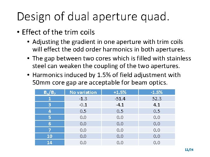
Design of dual aperture quad. • Effect of the trim coils • Adjusting the gradient in one aperture with trim coils will effect the odd order harmonics in both apertures. • The gap between two cores which is filled with stainless steel can weaken the coupling of the two apertures. • Harmonics induced by 1. 5% of field adjustment with 50 mm core gap are acceptable for beam optics. Bn/B 2 1 3 4 5 6 7 10 14 No variation -1. 3 -0. 1 0. 5 0. 0 0. 0 +1. 5% -51. 4 -4. 1 0. 5 0. 0 0. 0 -1. 5% 52. 3 4. 1 0. 5 0. 0 0. 0 11/24
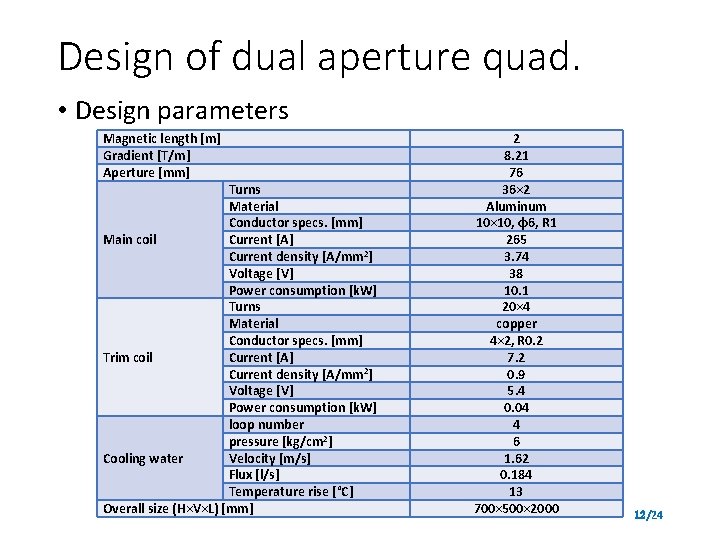
Design of dual aperture quad. • Design parameters Magnetic length [m] Gradient [T/m] Aperture [mm] Turns Material Conductor specs. [mm] Main coil Current [A] Current density [A/mm 2] Voltage [V] Power consumption [k. W] Turns Material Conductor specs. [mm] Current [A] Trim coil Current density [A/mm 2] Voltage [V] Power consumption [k. W] loop number pressure [kg/cm 2] Cooling water Velocity [m/s] Flux [l/s] Temperature rise [°C] Overall size (H×V×L) [mm] 2 8. 21 76 36× 2 Aluminum 10× 10, φ6, R 1 265 3. 74 38 10. 1 20× 4 copper 4× 2, R 0. 2 7. 2 0. 9 5. 4 0. 04 4 6 1. 62 0. 184 13 700× 500× 2000 12/24
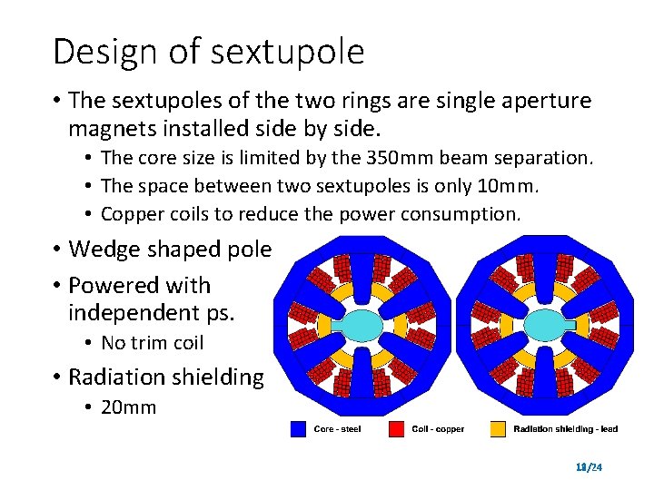
Design of sextupole • The sextupoles of the two rings are single aperture magnets installed side by side. • The core size is limited by the 350 mm beam separation. • The space between two sextupoles is only 10 mm. • Copper coils to reduce the power consumption. • Wedge shaped pole • Powered with independent ps. • No trim coil • Radiation shielding • 20 mm 13/24
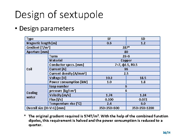
Design of sextupole • Design parameters Type Magnetic length [m] Gradient [T/m 2] Aperture [mm] Turns Material Conductor specs. [mm] Current [A] Coil Current density [A/mm 2] Voltage [V] Power consumption [k. W] loop number pressure [kg/cm 2] Cooling Velocity [m/s] water Flux [l/s] Temperature rise [°C] Overall size (H×V×L) [mm] SF 0. 6 10. 3 1. 0 287* 80 26× 6 Copper 7× 7, φ3. 5, R 0. 5 96 2. 5 1. 74 0. 100 2. 4 350× 600 6 6 SD 1. 2 18. 5 1. 8 1. 24 0. 072 6. 0 350× 1200 * The original gradient required is 574 T/m 2. With the help of the combined function dipoles, this requirement is halved and the power consumption is reduced to a quarter. 14/24
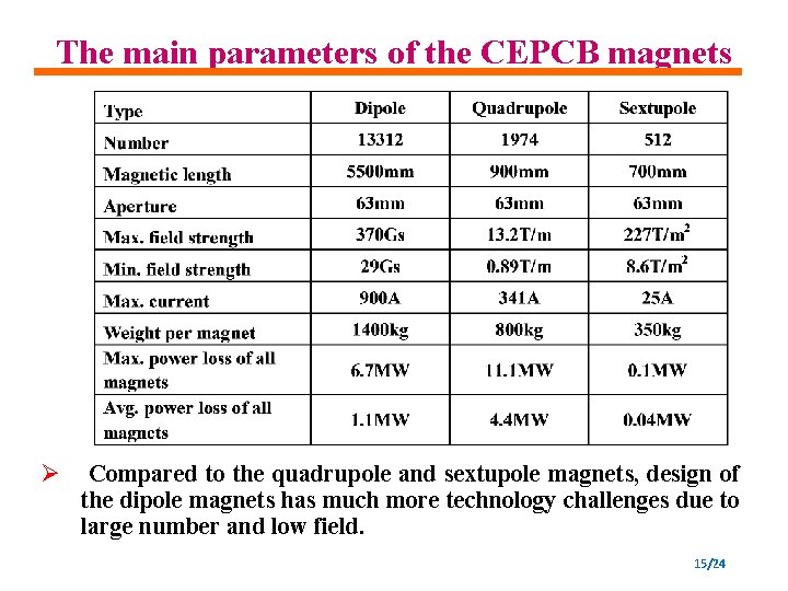
The main parameters of the CEPCB magnets Ø Compared to the quadrupole and sextupole magnets, design of the dipole magnets has much more technology challenges due to large number and low field. 15/24
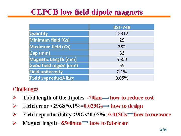
CEPCB low field dipole magnets Quantity Minimum field (Gs) Maximum field (Gs) Gap (mm) Magnetic Length (mm) Good field region (mm) Field uniformity Field reproducibility BST-74 B 13312 29 352 63 5500 55 0. 1% 0. 05% Challenges Ø Total length of the dipoles ~70 km how to reduce cost Ø Field error <29 Gs*0. 1%=0. 029 Gs how to design Ø Field reproducibility<29 Gs*0. 05%=0. 015 Gs Ø Magnet length ~5500 mm how to measure how to fabricate 16/24
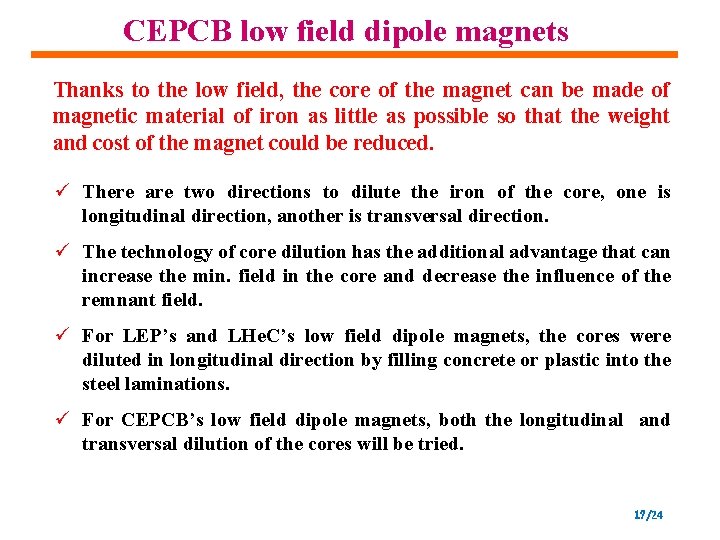
CEPCB low field dipole magnets Thanks to the low field, the core of the magnet can be made of magnetic material of iron as little as possible so that the weight and cost of the magnet could be reduced. ü There are two directions to dilute the iron of the core, one is longitudinal direction, another is transversal direction. ü The technology of core dilution has the additional advantage that can increase the min. field in the core and decrease the influence of the remnant field. ü For LEP’s and LHe. C’s low field dipole magnets, the cores were diluted in longitudinal direction by filling concrete or plastic into the steel laminations. ü For CEPCB’s low field dipole magnets, both the longitudinal and transversal dilution of the cores will be tried. 17/24
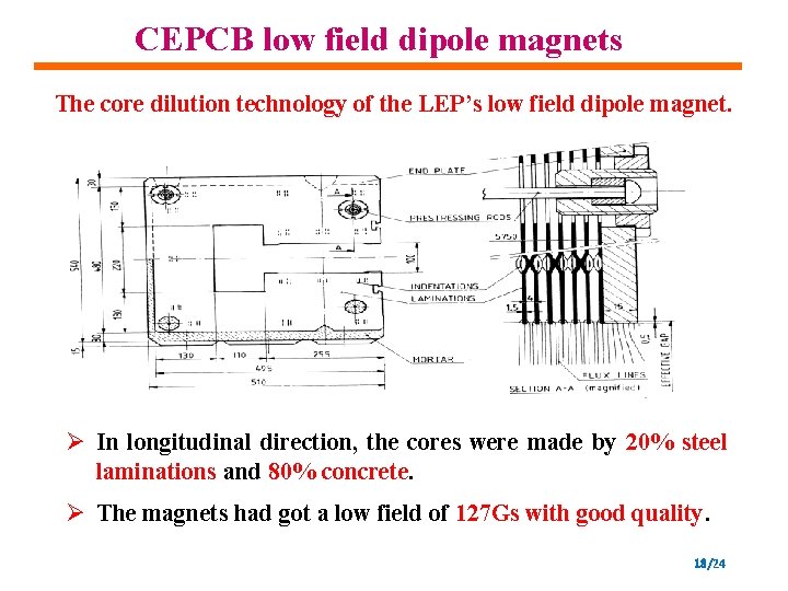
CEPCB low field dipole magnets The core dilution technology of the LEP’s low field dipole magnet. Ø In longitudinal direction, the cores were made by 20% steel laminations and 80% concrete. Ø The magnets had got a low field of 127 Gs with good quality. 18/24
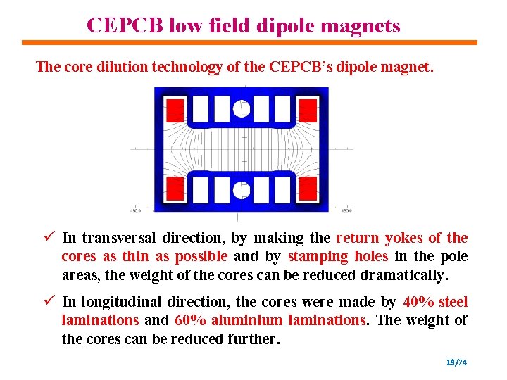
CEPCB low field dipole magnets The core dilution technology of the CEPCB’s dipole magnet. ü In transversal direction, by making the return yokes of the cores as thin as possible and by stamping holes in the pole areas, the weight of the cores can be reduced dramatically. ü In longitudinal direction, the cores were made by 40% steel laminations and 60% aluminium laminations. The weight of the cores can be reduced further. 19/24
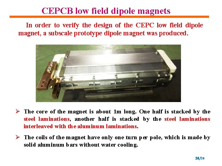
CEPCB low field dipole magnets In order to verify the design of the CEPC low field dipole magnet, a subscale prototype dipole magnet was produced. Ø The core of the magnet is about 1 m long. One half is stacked by the steel laminations, another half is stacked by the steel laminations interleaved with the aluminum laminations. Ø The coils of the magnet have only one turn per pole, which is made by solid aluminum bars without water cooling. 20/24
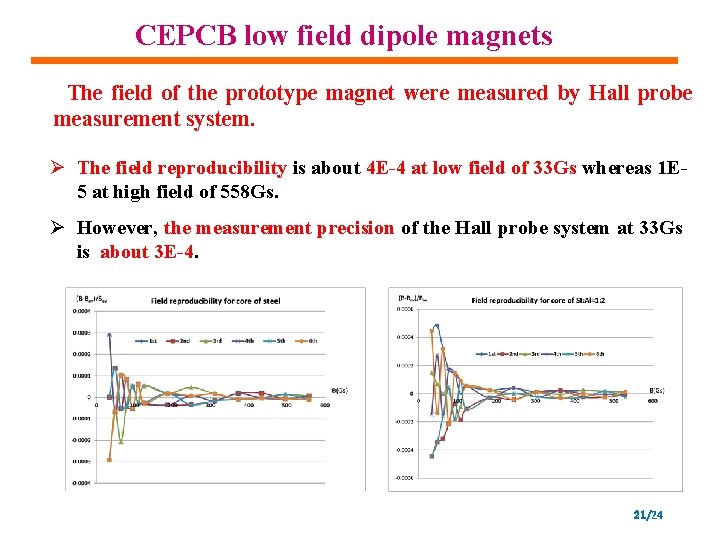
CEPCB low field dipole magnets The field of the prototype magnet were measured by Hall probe measurement system. Ø The field reproducibility is about 4 E-4 at low field of 33 Gs whereas 1 E 5 at high field of 558 Gs. Ø However, the measurement precision of the Hall probe system at 33 Gs is about 3 E-4. 21/24
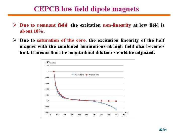
CEPCB low field dipole magnets Ø Due to remnant field, the excitation non-linearity at low field is about 10%. Ø Due to saturation of the core, the excitation linearity of the half magnet with the combined laminations at high field also becomes bad. It means that the longitudinal dilution should be adjusted. 22/24
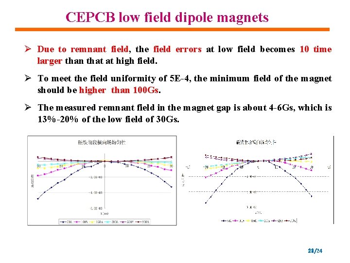
CEPCB low field dipole magnets Ø Due to remnant field, the field errors at low field becomes 10 time larger than that at high field. Ø To meet the field uniformity of 5 E-4, the minimum field of the magnet should be higher than 100 Gs. Ø The measured remnant field in the magnet gap is about 4 -6 Gs, which is 13%-20% of the low field of 30 Gs. 23/24
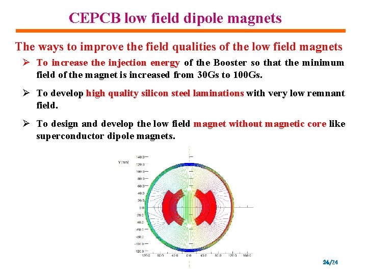
CEPCB low field dipole magnets The ways to improve the field qualities of the low field magnets Ø To increase the injection energy of the Booster so that the minimum field of the magnet is increased from 30 Gs to 100 Gs. Ø To develop high quality silicon steel laminations with very low remnant field. Ø To design and develop the low field magnet without magnetic core like superconductor dipole magnets. 24/24
- Slides: 24