CEPC booster magnet RD progress Wen Kang CEPC

CEPC booster magnet R&D progress Wen Kang CEPC Day, May 31, 2019

技术指标及其挑战 BST-63 B 16320 29 338 63 4700 55 0. 1% 0. 05% Quantity Minimum field (Gs) Maximum field (Gs) Gap (mm) Magnetic Length (mm) Good field region (mm) Field uniformity Field reproducibility Challenges Ø Total length of the dipoles ~75 km how to reduce cost Ø Field error <29 Gs*0. 1%=0. 029 Gs Ø Field reproducibility<29 Gs*0. 05%=0. 015 Gs Ø Magnet length ~4700 mm how to design how to fabricate how to measure

铁芯磁铁样机研制进展 ü The grain-oriented silicon steel laminations produced by Wuhan steel company were investigated, BH curves and coecive of the oriented and nonoriented steel laminations have an obvious difference. ü By using the two kinds of BH curves, the performance of the dipole magnet at low field level were simulated, the results showed that the magnet with the oriented steel laminations had a better field quality. Hc// Hc┴ Conventional low carbon steel 56 A/m Grain oriented steel 4 A/m 12 A/m

铁芯磁铁样机研制进展 ü At present, the mechanical design of a subscale prototype magnet was finished, the oriented steel laminations will be bought and the prototype magnet will be developed to verify the design.

Dipole magnet without iron cores ü The dipole magnet with CCT coils is composed of two or four canted solenoids, of which the excited currents have different direction. The By field in the magnet center is By=μ 0 I/(w*tan(α)), in which w is the distance between two turns, α is canted angle. The Bz field is compensated to nearly zero. ü The main advantage of CCT design is that it can get a good field quality in its 80% aperture without any field shimming, it means the field quality will not very sensitive to the mechanical errors of the coils.

Dipole magnet without iron cores ü In the case of superconducting magnets, the CCT coils are made by insert the conductors into the grooves that are fabricated on the surfaces of the supporting cylinders. ü The paths of the grooves on the cylinders are precisely determined by the equations of CCT’s curves so that the conductors in the groove can produce the expected field.

Dipole magnet without iron cores ü In the case of the dipole magnets of CEPCB, to reduce the cost of the magnet production, one simple way is to directly wind the conductor on the supporting cylinders. ü To fix the conductors in their right position, some small positioning cylinders are made on the surface of the supporting cylinder according to the equations of CCT’s curves.

Dipole magnet without iron cores ü However, the position errors directly winding the conductor on the supporting cylinders are probably not small enough to meet the field precision requirement. ü To ensure the field precision, the alternative way to make CCT coils is to directly fabricate them from the aluminum tubes. ü The CCT coils of the dipole magnet have four layers, so four aluminum tubes with the different diameters are used to fabricate the CCT coils. ü To improve the excitation efficiency, the canted angle of the CCT is 25 degree instead of 30 degree as in superconducting magnet case.

Dipole magnet without iron cores ü To investigate the procedures of fabrication, one part layer of CCT was produced from an aluminum tube. ü It is not easy to fabricate the coil and the mechanical precision is out of control after the fabrication is finished. ü After some insulation epoxy resin was carefully inserted in the gaps, each turn of the coil was restored to it right position. It will be tested on the bench of the Hall probe field measurement system in the lab.

CCT空芯线圈磁铁样机研制进展 The test part of CCT coil was measured in the field measurement lab. ü At the excited current of 60 A, the central field reached to 33 Gs as expected, and the field distribution also had a good agreement with the simulated ones. ü The field reproducibility at 30 Gs was better than 2 E-4, which was satisfied with the requirements.
 coil is that it have a")
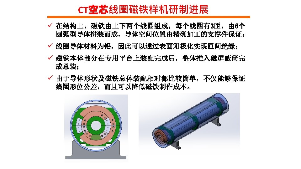
CT空芯线圈磁铁样机研制进展 ü The main advantage of Cosθ (CT) coil is that it have a higher efficiency than other air core magnets. By flatting the top and bottom of the shielding, the efficiency be increased by 5%. ü The disadvantage is that its field quality is sensitive to the mechanical errors of the coils, which is required to be less than 20 microns. ü To reduce the production cost, the structure of the CT coils is designed as simple as possible. The magnet have two coils, each coil has two layers and two turns, which are formed by aluminum bars with the same cross section areas.

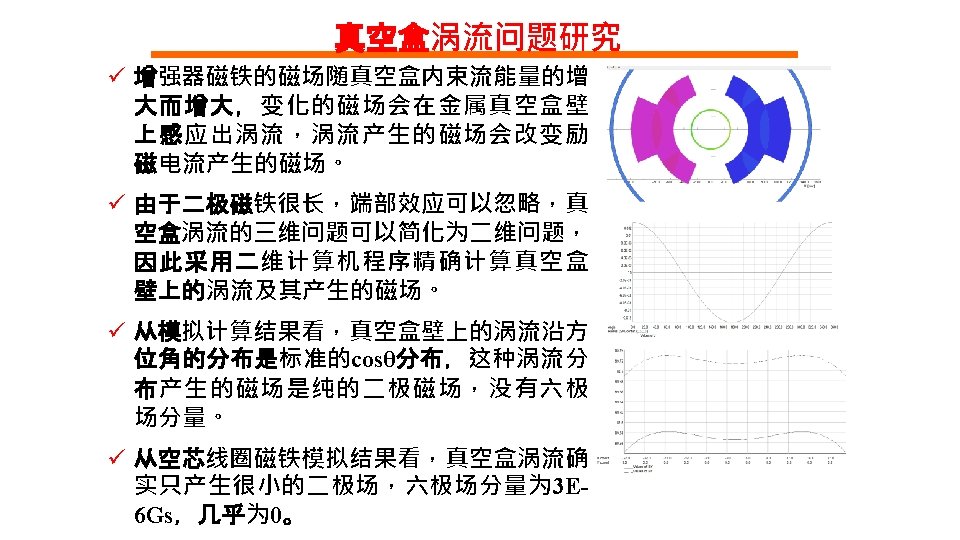
Dipole magnet without iron core ü Since the field of the dipole magnets for CEPCB will ramp with the beam energy, eddy current will be induced in the coil conductors. ü To study the influence of the eddy current on the field quality of the magnet, the field of the CT coils with different turns were simulated 4 turn per coil 2 turn per coil 6 turn per coil

Dipole magnet without iron core ü The field ramping curve is shown on the right, the field of the dipole magnet is ramped to the max. in 2. 5 s. ü For comparison, the DC field uniformity is simulated, it can be seen that the field distributions at low and high levels have no difference. ü However, when the field is ramping, the field distributions at low and high levels have large difference in the case of 2 turn per coil. DC case 2 turn AC case

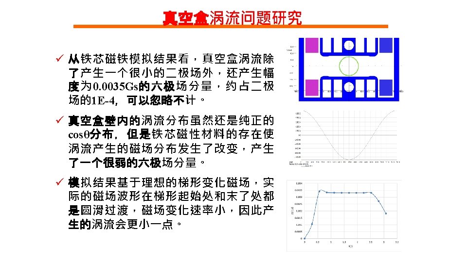
Dipole magnet without iron core ü In order to reduce the eddy current in the coil conductors, the turns of the coils are increased and the cross sections of the conductors per turn are reduced. ü The cases of 4 turns and 6 turns per coil are considered, the field simulations shows that the more turns per coil are, the better field quality at low level is. ü Although the AC field distribution of the 6 turn per coil is much closer to the DC field distribution, the structure of the 4 turn per coil is preferred because it is easier to be produced. 4 turn AC case 6 turn AC case
![三种设计方案磁铁参数对比 Iron Yoke Max. field [Gs] 338 Min. field [Gs] 29 Good field region](http://slidetodoc.com/presentation_image_h2/40265380a3880c35b1fd4645f5ca0d11/image-17.jpg "三种设计方案磁铁参数对比 Iron Yoke Max. field [Gs] 338 Min. field [Gs] 29 Good field region")
三种设计方案磁铁参数对比 Iron Yoke Max. field [Gs] 338 Min. field [Gs] 29 Good field region (mm) 55 Field uniformity 0. 1% Turns per magnet 2 Max. current (A) 856 Min. current (A) 73 Conductor area (mm 2) 1200 Max. current density(A/mm 2) 0. 71 Max. power loss (W) 425 Avg. power loss (W) 170 Inductance (m. H) 0. 08 Magnet size(mm) 330 Magnet length (mm) 4650 Magnet weight (ton) 1. 4 CT 338 29 55 0. 1% 4 1275 109 1945 0. 66 1320 528 0. 36 300 4632 0. 6 CCT 338 29 55 0. 1% 234 481 41 900 0. 53 1665 666 1. 5 360 4865 0. 65

High precision field measurement system By exploring several international companies that can produce Hall probe field measurement systems, we found one set of high precision system that could meet the requirements of the low field measurement.
")
High precision field measurement system The specifications of the measurement system (@F. W. Bell)

High precision field measurement system The performance of the Hall probe field measurement system was tested in the lab of IHEP. The low field of 30 Gs was produced by a permanent magnet that is absolutely stable.

High precision field measurement system The test results of 5 hours ü The precision of the system is 0. 006 Gs in the first hour and 0. 01 Gs in the second hour. ü The precision is very sensitive to the temperature change of the lab. From the third hour, the temperature of the lab changed 1 o. C, the precision became 0. 035 Gs. To realize the precision of 0. 01 Gs, the temperature change in the lab should be controlled within 0. 5 o. C

Summary ü From the view of the excitation efficiency at high field level, the design of the dipole magnet with iron cores is the best. To reduce the influence of the remnant field on the field quality at low field level, grain oriented silicon steel laminations will be used to stack the cores. ü The two designs (CT and CCT) of the dipole magnets without iron cores can meet the requirement of the field uniformity at low field level, they will consume more electricity power due to lower excitation efficiency at high field level. ü A set of Hall probe field measurement system with high precision was investigated and tested, it might reach the precision less than 0. 01 Gs in the case that the temperature change in the lab could be controlled within 0. 5 o. C

- Slides: 26