CEPC APDR SRF considerations Zhenchao LIU 2016 5

 Number of IPs Energy (Ge. V)")
 • Avoid pretzel orbit • Accommodate more bunches at Z/W energy")
 • The input power in pulse")

 C≈60 km")

 Circumference (km) SR loss/turn (Ge. V)")
 Zhaijiyuan 20160327&0408 APDR (H-low power) APDR (Z) 2 120 54 3.")
 Bunch train passing Bunch train space")
 Final Eacc/Initial Eacc Assume matching")
 C≈62 km")

 Final Eacc/Initial Eacc Assume matching Initial")
 Final Eacc/Initial Eacc Assume matching")
 Zhaijiyuan 20160327&0408 APDR (H-low power) APDR (Z) 2 120 54 3.")


- Slides: 24
CEPC APDR SRF considerations Zhenchao LIU 2016. 5. 25
Primary parameter for CEPC double ring (wangdou 20160219) Number of IPs Energy (Ge. V) Circumference (km) SR loss/turn (Ge. V) Half crossing angle (mrad) Piwinski angle Ne/bunch (1011) Bunch number Beam current (m. A) SR power /beam (MW) Bending radius (km) Momentum compaction (10 -5) IP x/y (m) Emittance x/y (nm) Transverse IP (um) x/IP y/IP VRF (GV) f RF (MHz) Nature z (mm) Total z (mm) HOM power/cavity (kw) Energy spread (%) Energy acceptance by RF (%) n Life time due to beamstrahlung_cal (minute) F (hour glass) Lmax/IP (1034 cm-2 s-1) Pre-CDR H-high lumi. H-low power Z 2 120 54 3. 1 0 0 3. 79 50 16. 6 51. 7 6. 1 3. 4 0. 8/0. 0012 6. 12/0. 018 69. 97/0. 15 0. 118 0. 083 6. 87 650 2. 14 2. 65 3. 6 0. 13 2 6 0. 23 47 2 120 54 2. 96 14. 5 2 3. 79 50 16. 9 50 6. 2 3. 0 0. 306/0. 0012 3. 34/0. 01 32/0. 11 0. 04 0. 11 3. 7 650 3. 3 4. 4 3. 3 0. 13 2 2. 2 0. 49 53 15 2. 85 50 16. 9 50 6. 2 2. 5 0. 25/0. 00136 2. 45/0. 0074 24. 8/0. 1 0. 03 0. 11 3. 62 650 3. 1 4. 1 2. 2 0. 13 2 2. 2 0. 47 36 11. 5 2 2. 81 40 10. 1 30 6. 2 2. 6 0. 22/0. 001 2. 67/0. 008 24. 3/0. 09 0. 04 0. 11 3. 6 650 3. 2 4. 2 1. 5 0. 13 2 2. 2 0. 47 41 15 2. 67 44 10. 5 31. 2 6. 2 2. 2 0. 268 /0. 00124 2. 06 /0. 0062 23. 5/0. 088 0. 032 0. 11 3. 53 650 3. 0 4. 0 1. 3 0. 13 2 2. 1 0. 47 32 2 45. 5 54 0. 062 15 8. 5 0. 46 1100 45. 4 2. 8 6. 1 3. 5 0. 08/0. 001 0. 62/0. 002 7/0. 046 0. 005 0. 084 0. 12 650 3. 9 4. 0 0. 99 0. 05 0. 68 2. 04 0. 73 2. 97 0. 82 2. 96 0. 69 2. 03 0. 81 2. 01 1. 1 0. 27 0. 95 3. 61
Advantage: bypass (pp) • Avoid pretzel orbit • Accommodate more bunches at Z/W energy • Reduce AC power with crab waist collision bypass (pp)
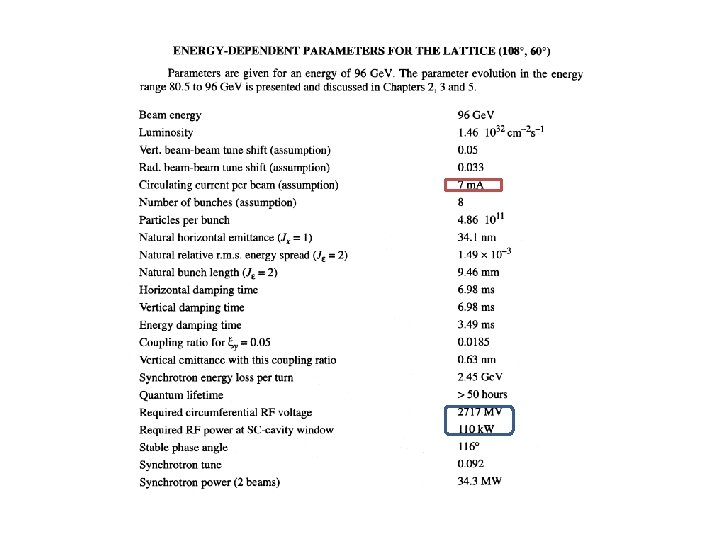
Input power requirements(at CEPC meeting 2016. 4. 8) • The input power in pulse should be equal to the beam power of bunch train (if do not consider reflection ……). • Or the bunch distance from each other is enough to power up the cavity field again. • Higher Eacc is much better when input power is not enough as the stored energy in cavity is proportional to Eacc^2. • Reliable ceramic window for the high peak input power. • The design is very challenging for the RF!!!!!
New idea:APDR
New SRF layout IP 1 RF station Double Ring (1 km/3 km) C≈60 km RF&DR center 30°equispaced IP 3
bunch 3. 3 us t 26. 7 us
Wangdou 20160219 Number of IPs Energy (Ge. V) Circumference (km) SR loss/turn (Ge. V) Half crossing angle (mrad) Piwinski angle Ne/bunch (1011) Bunch number Beam current (m. A) SR power /beam (MW) Bending radius (km) Momentum compaction (10 -5) IP x/y (m) Emittance x/y (nm) Transverse IP (um) x/IP y/IP VRF (GV) f RF (MHz) Nature z (mm) Total z (mm) HOM power/cavity (kw) Energy spread (%) Energy acceptance by RF (%) n Life time due to beamstrahlung_cal (minute) F (hour glass) Lmax/IP (1034 cm-2 s-1) Pre-CDR H-high lumi. H-low power Z 2 120 54 3. 1 0 0 3. 79 50 16. 6 51. 7 6. 1 3. 4 0. 8/0. 0012 6. 12/0. 018 69. 97/0. 15 0. 118 0. 083 6. 87 650 2. 14 2. 65 3. 6 0. 13 2 6 0. 23 47 2 120 54 2. 96 14. 5 2 3. 79 50 16. 9 50 6. 2 3. 0 0. 306/0. 0012 3. 34/0. 01 32/0. 11 0. 04 0. 11 3. 7 650 3. 3 4. 4 3. 3 0. 13 2 2. 2 0. 49 53 15 2. 85 50 16. 9 50 6. 2 2. 5 0. 25/0. 00136 2. 45/0. 0074 24. 8/0. 1 0. 03 0. 11 3. 62 650 3. 1 4. 1 2. 2 0. 13 2 2. 2 0. 47 36 11. 5 2 2. 81 40 10. 1 30 6. 2 2. 6 0. 22/0. 001 2. 67/0. 008 24. 3/0. 09 0. 04 0. 11 3. 6 650 3. 2 4. 2 1. 5 0. 13 2 2. 2 0. 47 41 15 2. 67 44 10. 5 31. 2 6. 2 2. 2 0. 268 /0. 00124 2. 06 /0. 0062 23. 5/0. 088 0. 032 0. 11 3. 53 650 3. 0 4. 0 1. 3 0. 13 2 2. 1 0. 47 32 2 45. 5 54 0. 062 15 8. 5 0. 46 1100 45. 4 2. 8 6. 1 3. 5 0. 08/0. 001 0. 62/0. 002 7/0. 046 0. 005 0. 084 0. 12 650 3. 9 4. 0 0. 99 0. 05 0. 68 2. 04 0. 73 2. 97 0. 82 2. 96 0. 69 2. 03 0. 81 2. 01 1. 1 0. 27 0. 95 3. 61
Zhaijiyuan 20160327 PDR(HL) Zhaijiyuan 20160327&0408 APDR (H-low power) APDR (Z) 2 120 54 3. 1 0 0 3. 79 1 16. 6 53. 2 6. 1 6. 87 650 384 15. 8 63. 1 275 / 105. 6 5 4 6 96 514 268 1. 8 3. 6 2 4 E 10 1. 156 2. 36 e 6 0. 28 2 120 54 2. 96 15 2. 85 1 16. 96 51 6. 2 3. 65 650 384 20. 6 35. 2 263. 4 2220 382. 5 2 6 10 64 206 268 0. 54 0. 8 2 2 E 10 0. 097 1. 97 e 5 3. 3 2 120 54 2. 96 15 2. 67 15 x 3 10. 5 31. 2 6. 2 5. 16 650 498 22. 6 55. 5 -55 126 1148 62. 7 2 4(3) 21 126 206 268 0. 54 0. 485 2 2 E 10 2. 045 4. 18 e 6 0. 077 2 45. 5 54 0. 062 15 8. 5 0. 46 367 x 3 45. 4 2. 8 6. 1 0. 357 650 48 16. 2 80. 2 -79. 8 117 1237 5. 6 2 4 2 12 206 268 0. 54 0. 361 2 2 E 10 2. 243 4. 58 e 6 0. 071 -0. 27 158. 7 5. 484 / 100 -1. 16 107. 4 5. 484 0. 3 -160 27% -0. 111 126. 9 5. 484 26. 7 ~100 -0. 234 65. 3 5. 484 26. 7 ~100 Pre-CDR Number of IPs Energy (Ge. V) Circumference (km) SR loss/turn (Ge. V) Half crossing angle (mrad) Piwinski angle Ne/bunch (1011) Bunch number Beam current (m. A) SR power /beam (MW) Bending radius (km) VRF (GV) f RF (MHz) Cavity No. Cavity gradient Accelerating phase CW power/cavity (k. W) Peak power/train (k. W) Total Power (MW) Cell/cavity Cavity/module Module/station Total module R/Q (Ω) G HOM loss factor/cavity (V/p. C) HOM power/cavity (k. W) Working Temperature(K) Q 0 τ(ms) QL Bandwidth(k. Hz) Detuning F (k. Hz) Stored energy/cavity(J) Frev(k. Hz) Gap length (us) η(RF to beam efficiency)(%)
Accelerator gradient decrease in one RF cavity (Z) Bunch train passing Bunch train space Final Eacc/Initial Eacc Assume matching Initial Eacc(MV/m) RF cycles Field evolution in cavity Field decrease vs. various initial field gradient of the cavity
Accelerator gradient decrease in one RF cavity (H-Low power) Final Eacc/Initial Eacc Assume matching Initial Eacc(MV/m) RF cycles Field evolution in cavity Field decrease vs. various initial field gradient of the cavity
New SRF layout IP 1 RF station Double Ring (1 km/3 km) C≈62 km RF&DR center 22. 5°equispaced IP 3
bunch 3. 3 us t 20 us
Accelerator gradient decrease in one RF cavity (Z) Final Eacc/Initial Eacc Assume matching Initial Eacc(MV/m) RF cycles Field evolution in cavity Field decrease vs. various initial field gradient of the cavity
Accelerator gradient decrease in one RF cavity (H-Low power) Final Eacc/Initial Eacc Assume matching Initial Eacc(MV/m) RF cycles Field evolution in cavity Field decrease vs. various initial field gradient of the cavity
Zhaijiyuan 20160327 PDR(HL) Zhaijiyuan 20160327&0408 APDR (H-low power) APDR (Z) 2 120 54 3. 1 0 0 3. 79 1 16. 6 53. 2 6. 1 6. 87 650 384 15. 8 63. 1 275 / 105. 6 5 4 6 96 514 268 1. 8 3. 6 2 4 E 10 1. 156 2. 36 e 6 0. 28 2 120 54 2. 96 15 2. 85 1 16. 96 51 6. 2 3. 65 650 384 20. 6 35. 2 263. 4 2220 382. 5 2 6 10 64 206 268 0. 54 0. 8 2 2 E 10 0. 097 1. 97 e 5 3. 3 2 120 54 2. 96 15 2. 67 11 x 4 10. 5 31. 2 6. 2 5. 16 650 498 22. 6 55. 3 -55 126 843 62. 7 2 6(3, 2) 10(11) 126 206 268 0. 54 0. 485 2 2 E 10 2. 045 4. 18 e 6 0. 077 2 45. 5 54 0. 062 15 8. 5 0. 46 275 x 4 45. 4 2. 8 6. 1 0. 357 650 48 16. 2 80. 1 -79. 9 117 884 5. 6 2 6 1 12 206 268 0. 54 0. 361 2 2 E 10 2. 243 4. 58 e 6 0. 071 -0. 27 158. 7 5. 484 / 100 -1. 16 107. 4 5. 484 0. 3 -160 27% -0. 111 126. 9 5. 484 20 ~100 -0. 234 65. 3 5. 484 20 ~100 Pre-CDR Number of IPs Energy (Ge. V) Circumference (km) SR loss/turn (Ge. V) Half crossing angle (mrad) Piwinski angle Ne/bunch (1011) Bunch number Beam current (m. A) SR power /beam (MW) Bending radius (km) VRF (GV) f RF (MHz) Cavity No. Cavity gradient Accelerating phase CW power/cavity (k. W) Peak power/train (k. W) Total Power (MW) Cell/cavity Cavity/module Module/station Total module R/Q (Ω) G HOM loss factor/cavity (V/p. C) HOM power/cavity (k. W) Working Temperature(K) Q 0 τ(ms) QL Bandwidth(k. Hz) Detuning F (k. Hz) Stored energy/cavity(J) Frev(k. Hz) Gap length (us) η(RF to beam efficiency)(%)
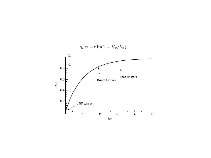
Question? • Can the 4 bunch or 3 bunch structure be calculated as CW mode? • Stable state:Vb=Vc, ψ=-ϕs • Vb(no beam period): – e^-t/τ=e^-27/2045=0. 987 – e^-t/τ=e^-27/2243=0. 988 – e^-t/τ=e^-27/2045=0. 99 – e^-t/τ=e^-20/2243=0. 991 • Vc(no beam period): – 0. 983→ 1 ; 0. 99→ 1;
LEPII LEP layout
LEP II
What is the best β? Pulse period optimum QL=4. 5 e 5 β=0. 3 β= P-/P+ β=4366 β=1 0. 8 t/τ 0. 6 0. 4 t/τ 0. 2 0. 3
What is the best cavity for APDR? • R/Q=Vc 2/ωU • A lower R/Q can give a high U at the same cavity voltage (or gradient) • The gradient is more stable at higher U when the input power is not enough at the pulse period. • It is an opposite design scheme comparing with low-loss cavity or others • Reduced R/Q can also decrease the detuning frequency • R/Q Riris loss factor • Cavity can work at a lower gradient with the same U
Thanks!